

KMC Controls KMD-7001, KMD-7052, KMD-7051, KMD-7053, KMD-7003 Installation & Operation Manual
...Page 1
Installation & Operation Guide
Direct Digital VAV Controllers
KMD-7001/7051 - VAV Terminal Units
KMD-7002/7052 - Dual Duct VAV Units
KMD-7003/7053 - Fan Induction Units
907-019-01C
1
Page 2
Introduction
This section provides a brief overview of the KMD-7001, 7002 and 7003 Direct
Digital Controllers. These units are intended for use with standard 1/2” round or
3/8” square damper shafts.
Note:
For installations using a 3/8” round shaft, you will need the HFO-0011 shaft
adaptor.
Review this material before you attempt to install the controller.
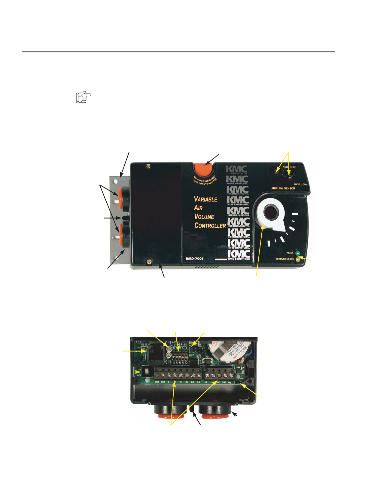
Non-Rotational Bracket
Conduit
Plugs
Lock
Ta b
Removable
Conduit Plate
Access Cover
Gear Disengagement
Button
Drive Hub
Illustration 1. Controller Components
The following illustrations show the different model connection details.
Air Sensor Inputs
Status
LEDs
Isolation
Lamps
RJ-12
Conn.
Network
Switch
Terminal Connections
Input/EOL
Switches
RST Jumper
Power
Jumper
Conduit
Plate
Lock Tab
Illustration 2. KMD-7001 Controller Connector Detail
2
Page 3
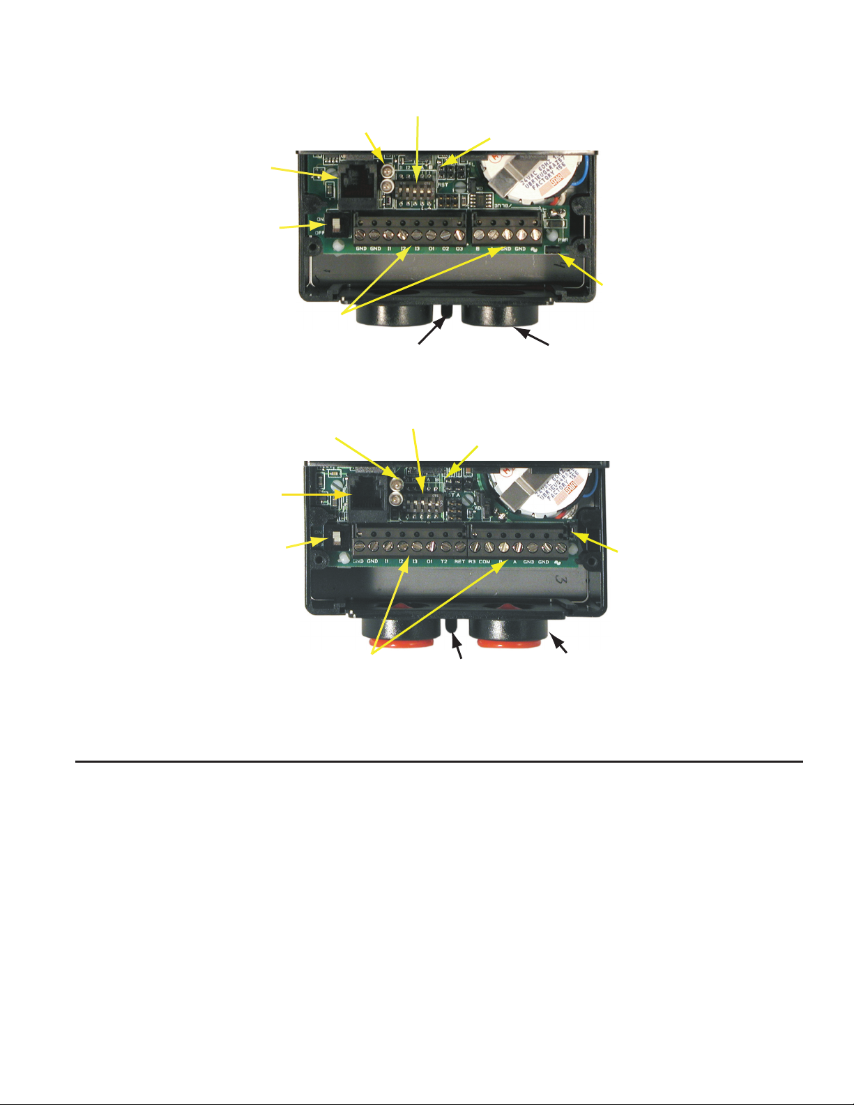
Isolation Lamps
RJ–12
Conn.
Network
Switch
Terminal Connections
Illustration 3. KMD-7002 Controller Connector Detail
Lock Tab
Input/EOL
Switches
RST Jumper
Power
Jumper
Conduit
Plate
Installation
Isolation
Lamps
RJ–12
Conn.
Network
Switch
Terminal Connections
Input/EOL
Switches
RST Jumper
Lock Tab
Power
Jumper
Conduit
Plate
Illustration 4. KMD-7003 Controller Connector Detail
This section provides important instructions and guidelines for installing the
KMD-7001, 7002 and 7003 series controllers. Carefully review this information
prior to attempting installation.
Preparation
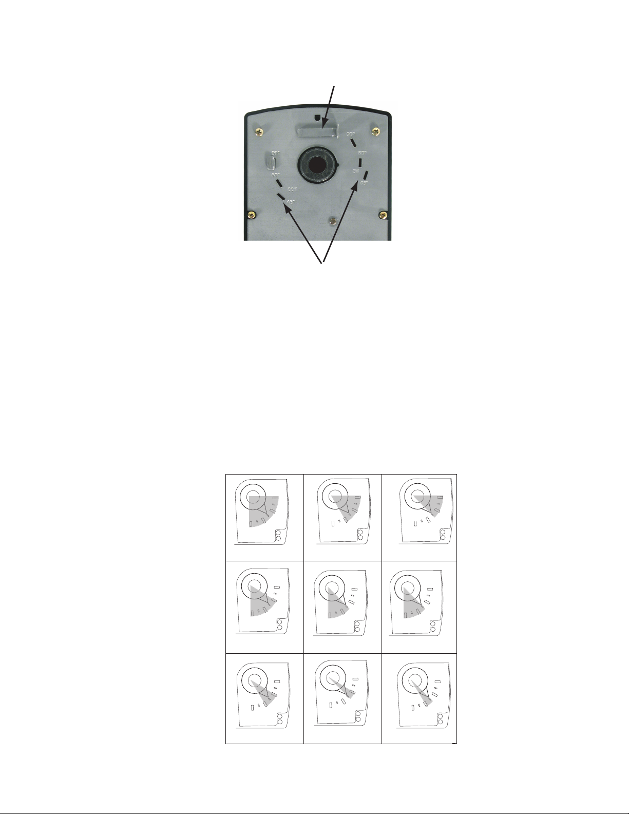
Prior to mounting the controller, the rotational limits must be set using stop pins.
These settings limit the shaft rotation in the clockwise (CW) and counterclockwise (CCW) directions. (Refer to Illustration 5.)
3
Page 4
90/90
5/90
90/
90/45
90/45
45/60
Installation KMD-7001/7002/7003 Direct Digital Controller Installation & Operation Guide
Stop Pin
(1 of 2)
Stop Selections
Illustration 5. Controller Stop Selections
To set the rotational limits:
1. Turn the controller over so you have access to the back.
2. Locate the two stop pins installed in the back of the unit. (You will find one
pin in a CCW setting and one in a CW setting.)
3. Identify the limits you wish to use.
The maximum amount of shaft rotation is 90°. Placing a stop pin in both 90°
slots allows the actuator the full 90° of travel. Placing a stop pin in any other slot
restricts actuator motion in the indicated direction (CW or CCW). Refer to
Illustration 6 for pin placement and travel. The first number represents the CCW
pin and the second the CW pin (CCW/CW).
60/90
4
60
60/60
Illustration 6. Controller Travel and Stop Selections
4
60/45
Page 5

KMD-7001/7002/7003 Direct Digital Controller Installation & Operation Guide Installation
Caution
Both stop pins must be installed to prevent actuator damage.
4. If the stop pins are positioned as required, you may leave them in place. If
not, remove the appropriate pin(s) and place it in the correct slot.
Mounting
The controller will be mounted directly over the damper shaft. A minimum shaft
length of 1-3/4” (45 mm) is required. The base of the controller must contact the
mounting surface to allow installation of a bracket to prevent the controller from
rotating.
Note:
The controller should be mounted close enough to the Pitot tubes to allow a
maximumn 24” length of tubing to reach the controller inputs.
Proceed as follows:
1. Back out the set screws in the shaft collar so the shaft can fit through the collar.
2. Place the controller on the damper shaft in the approximate final position.
3. Position the non-rotation bracket and secure it using #8 or #10 self-tapping
screws. Make certain the notch in the bracket securely engages the Lock tab
on the controller. (Refer to Illustration 1.)
4. Manually position the damper in the full open position.
5. Adjust the drive hub as follows:
A. If the damper rotates counter clockwise to close, depress the gear disengagement button and rotate the drive hub to the full clockwise position
then release the button.
B. If the damper rotates clockwise to close, depress the gear disengagement
button and rotate the drive hub to the full counter clockwise position then
release the button.
6. Tighten the two set screws in the drive hub to approximately 50–inch pounds
(5.65 N-m) to lock the hub to the shaft.
Wiring
The controller comes with a removable conduit plate. The plate provides two
1/2” female threaded conduit couplings. If conduit is to be used, note the
following:
◆ The conduit plate may be removed by removing the two screws that secure
the access cover and removing the cover. Connect the required conduit and
replace the plate in the controller housing.
◆ The plugs may also be sliced to allow wiring to enter the controller with a
minimum of outside contaminates.
5
Page 6

Installation KMD-7001/7002/7003 Direct Digital Controller Installation & Operation Guide
Input Connections
All input and output connections are made using the connectors beneath the
access cover. Remove the two screws that secure this cover to remove the cover
and complete input and output connections as discussed below.
Universal Inputs
Inputs are configured per the model.
7001/7051 and 7003/7053
Inputs are connected to the wire terminal strip using connections I1–I3. Observe
the following guidelines. (Refer to Illustration 2 and 4.)
◆ Connect device inputs to the input terminal connections for inputs I1–I3.
◆ Connect all grounds to the common GND reference terminals.
◆ If input pull-ups are required, refer to “Board Configuration” later in this
section.
Note:
RS-485 Inputs
Input #1 (I1) is typically assigned to the space temperature sensor input, otherwise it is available for use. Inputs 2 and 3 are available for optional inputs.
7002/7052
These inputs are the same as on the 7001/7003 series except for Input #3 (I3). The
I3 input on these models is dedicated to the TSP Slave Flow Sensor input. (Refer
to Illustration 3.)
To make connections to a KMC Tier 2 (RS-485) network use the RS-485 connections on the terminal strip. If the Controller is at the End-of-Line, refer to “Configuration” after connections are completed.
Detail
The End-of-Line connection will have only one wire attached to the A and B
terminals.
◆ For reliable operation, use Belden cable model #82760 or equivalent (18 gauge,
twisted, shielded, 50 picofarads or less) for all network terminal block connections.
◆ Connect the nodes of the network in a daisy-chain arrangement. This means:
Connect the A terminal in parallel with all other A terminals.
Connect the B terminal in parallel with all other B terminals.
◆ Connect the shields of the cable together at each controller.
◆ Connect the shield drain wire to an earth ground only at one end of the
segment; tape back the shield ground at the other end.
6
Page 7

KMD-7001/7002/7003 Direct Digital Controller Installation & Operation Guide Installation
Airflow Sensor
An Airflow Sensor is incorporated as one of the inputs to the controller. Remove
the plugs and connect the tubing from the Pitot assembly to the airflow sensor
inputs above the drive hub. (Refer to Illustration 1.)
Connecting Outputs
The Controller provides three output connection options configured according to
the model. Locate your model from the units discussed below:
7001/7051 and 7002/7052
These models provide three universal outputs O1, O2 and O3. They will provide
0/12 VDC at a maximum of 50 mA in Digital mode or 0-10 VDC at a maximum
of 30 mA in Analog mode. Returns are connected to the GND connections on the
left end of the strip. (Refer to Illustration 2 and 3.)
7003/7053
These models are unique as described below: (Refer to Illustration 4.)
Out 1 – This is a universal output that may be used as an output option. Output
ratings are the same as on the other models.
T2 – This Triac output will switch a maximum voltage of 30 VAC. It is rated for a
minimum current of 20 mA and a maximum of 1A. Use the RET terminal for
the triac return.
R3 – This output is assigned as the Normally Open Relay Output. The output
will switch up to 30 VAC/DC at up to 2A maximum. The return connects to the
COM terminal.
RJ-12
An RJ–12 connector is provided for connection to the KMD-1001 NetView or the
KMD-11xx Series NetSensor or a PC. Simply place the appropriate cable connector in the provided RJ–12 connector and connect the other end to the device.
Board Configuration
Configuration settings may be required for the inputs or the RS-485 connection.
If you must activate or deactivate pull-ups on the inputs or set the end-of-line
termination for the RS-485 connection, refer to Illustration 7 to locate the
switches for these settings.
7
Page 8

Installation KMD-7001/7002/7003 Direct Digital Controller Installation & Operation Guide
RJ–12
Conn.
Illustration 7. Typical Input Pull-up and EOL Switch Placement
Input Pull-Up/EOL
Switches
Proceed as follows:
1. If the access cover is still on the controller, remove the two screws that
secure the cover, then remove the cover.
2. Locate the switch next to the isolation lamps behind the terminal strip. (See
Illustrations 4.)
3. Set the switches as follows:
A. If the RS-485 connection is the End-of-Line controller, verify that both
switches 4 & 5 (A & B) are in the ON position. Otherwise, the switches
remain in the default “OFF” position.
B. If one or more inputs require a pull-up, verify that the appropriate
switches (I1–I3) is set to the default “ON” position. For devices supplying their own voltage/current for passive devices, move the switch to
the “OFF” position.
4. After you set the switches, replace the controller cover and secure it with
Power Connection
Connect the 24 VAC supply voltage to the power terminal block on the lower
right side of the controller near the PWR jumper. Connect the GND side of the
transformer to the GND terminal and the AC Phase side to the AC terminal.
Power is applied to the controller when the power supply (or transformer) is
plugged in and the PWR jumper is in place. Illustration 7 shows a typical connection diagram for the controller.
the screws you removed earlier.
8
Page 9

KMD-7001/7002/7003 Direct Digital Controller Installation & Operation Guide Installation
KMD-7003
REHEAT
RET
T2 R3
SERIES FAN
START CIRCUIT
FAN
COM
GNDBA
W
R
H
HWR
APPLICATION DRAWING FOR KMD-7003
VAV WITH FAN AND WET REHEAT
FROM PREVIOUS DEVICE "B"
FROM PREVIOUS DEVICE "A"
TO NEXT DEVICE "B"
TO NEXT DEVICE "A"
24VAC 120VAC
24VAC THERMAL
ACTUATOR
B
*
HWS
(OPTIONAL IN PLACE
OF NETSENSOR)
24" OF 1/4" TUBING
SSS-1000
Room ˚F
FLOW
NETSENSOR
KMD-1151 / KMD-1171
STE-5013
H
Min 0
Max 1
V. FCTR
MAXC. FCTRMIN
FLOW
RJ-12 PC/NETSENSOR PORT
L
6-CONDUCTOR CABLE
ROOMTEMP
GNDGND
IN1 IN2
IN3 OUT1
B
A
C
READY
L
H
COMMUNICATIONS
KMDIGITAL
KMC
ONTROLLER
IR
ARIABLE
OLUME
C
AVV
KMD-7003
*For electric reheat applications, use a separate 24 VAC transformer to isolate the relay through the Triac.
Illustration 8. Typical KMD-7003 Application
Note:
Typical Application Diagrams may be obtained by contacting KMC Controls
Technical Support at 574-831-5250 or e-mail us at techs@kmccontrols.com.
Network Configuration
Prior to operating the controller, it must be configured using the Hardware
Configuration Manager (HCM) application supplied with WinControl. Refer to
the WinControl XL User’s Manual and the KMC Digital Applications Manual for
additional information.
Note:
All controllers on the same network must be configured for the same baud rate
and each controller assigned a unique address.
Programming
Refer to the KMC Digital Applications Manual for information on how to program the controller.
9
Page 10

Operation
Once configured, programmed and powered up, the controller requires very
little user intervention.
Controls and Indicators
The following sections describe the controls and indicators found on the
controller.
Network ON/OFF
The network ON/OFF switch is located near the RJ–12 connector. Use this switch
to enable or disable the RS-485 network connection. When the switch is ON the
controller can communicate on the network; when it is OFF, the controller is
isolated from the network.
Alternately, you may remove the Isolation Lamps to isolate the controller from
the network.
Status LEDs
Two Status LEDs are located on the left side of the controller above the power
connector terminal. They are used to indicate the following:
Ready – This LED flashes rapidly whenever the controller is operating normally.
You can consider this the same as a power LED.
Communications – This LED indicates when the controller is transmitting over
the RS-485 network connection.
Isolation Lamps
Two Isolation Lamps are located near the RJ–11 connector. These lamps serve
three functions:
◆ Removing the lamps will open the RS-485 circuit and isolate the controller
◆ If one, or both, lamps are lit, it indicates the network is improperly phased.
◆ If the voltage or current on the network exceeds safe levels, the lamps operate
from the network.
This means that the ground potential of the controller is not the same as other
controllers on the network
as fuses and may protect the controller from damage.
10
Page 11

KMD-7001/7002/7003 Direct Digital Controller Installation & Operation Guide Operation
Resetting the Controller
If the controller appears to be operating incorrectly, or is not responding to
commands, you may need to reset the controller.
Note
Resetting the controller will restore the factory default configuration.
It may be necessary to re-configure the controller with HCM to establish
normal communications and operation. Re-programming may also be required.
To reset the controller, proceed as follows.
1. Remove the two screws that secure the Access Cover, then remove the
cover.
2. Locate the jumper block next to the input pull-up switches (see Illustration
8).
RST
Jumper
Illustration 8. Reset (RST) Jumper Location
3. Power off the controller. (Remove the PWR jumper.)
4. Locate the RST pins and place a jumper across them.
5. Power up the controller. Wait until the Ready LED flashes normally.
6. Power off the controller.
7. Remove the jumper from the RST pins.
8. Replace the PWR jumper.
8. Replace the controller cover.
9. Re-configure the controller if necessary.
11
Page 12

Disclaimer
The material in this document is provided for information purposes only.
The contents and the product(s) described herein are subject to change
without notice. KMC Controls, Inc. makes no representations or warranties
with respect to this document. In no event shall KMC Controls, Inc. be
liable for any damages, direct or incidental, arising out of or related to the
use of this document.
Important Notices
The KMC logo is a trademark of KMC Controls, Inc.©2003, KMC Controls,
Inc. All rights reserved.
No part of this publication may be reproduced, transmitted, transcribed,
stored in a retrieval system, or translated into any language in any form by
any means without the written permission of KMC Controls, Inc.Printed in
U.S.A.
Technical Support
If you have any questions about this technical document or need additional
details, please call KMC Controls technical services at 574-831-5250 or email us at techs@kmccontrols.com.
12
KMC Controls
P.O. Box 497
19476 Industrial Drive
New Paris, IN 46553
U.S.A.
TEL: 574.831.5250
FAX: 574.831.5252
E-mail: info@kmccontrols.com
907-019-01C
 Loading...