

Page 1
Installation and Operation Guide
KMD-5575 Network Repeater-Isolator
Contents
Introduction .........................................................................................................................3
Installation
Mounting
Wiring and Terminal Blocks
Network Connections
Conguration/EOL
Power Connection
Indicators and Operation
Accessories
Specications
KMD-5575 1 Installation and Operation Guide
............................................................................................................................3
........................................................................................................................3
.........................................................................................4
...................................................................................................4
........................................................................................................7
.........................................................................................................7
...................................................................................................8
...........................................................................................................................8
.......................................................................................................................8
873-019-02D
Page 2

Important Notices
©2008 KMC Controls
The KMC logo is a trademark of KMC Controls, Inc. All rights reserved.
No part of this publication may be reproduced, transmied, transcribed,
stored in a retrieval system, or translated into any language in any form by
any means without the wrien permission of KMC Controls, Inc. Printed in
U.S.A.
Disclaimer
The material in this document is provided for information purposes only. The
contents and the product(s) described herein are subject to change without
notice. KMC Controls, Inc. makes no representations or warranties with
respect to this document. In no event shall KMC Controls, Inc. be liable for
any damages, direct or incidental, arising out of or related to the use of this
document.
KMC Controls
P.O. Box 497
19476 Industrial Drive
New Paris, IN 46553
U.S.A.
TEL: 574.831.5250
FAX: 574.831.5252
E-mail: info@kmccontrols.com
KMD-5575 2 Installation and Operation Guide
Page 3
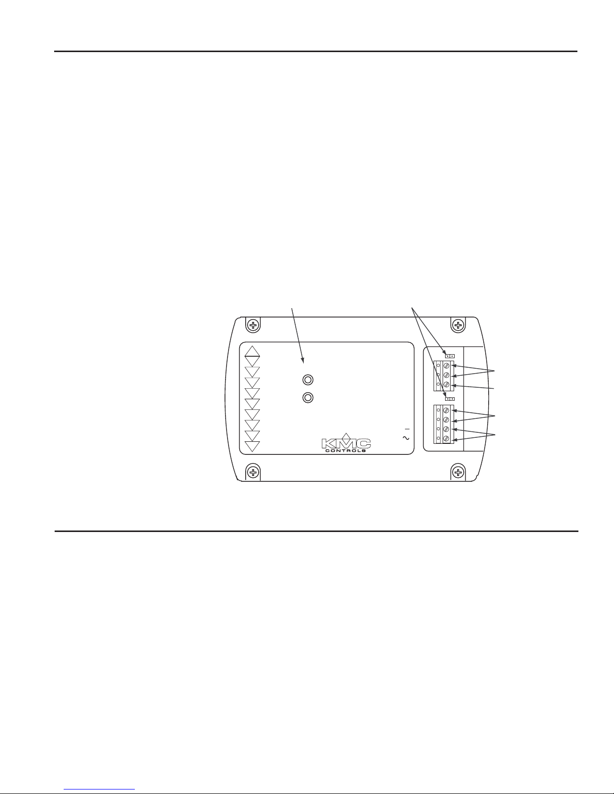
Introduction
Status LEDs
Network 2
Connections
Network 1
Connections
Power
Connection
EOL Te rminations
Circuit Ground
Repeater
KMD-5575
STATUS
2
1
EOL
A
B
GND
EOL
A
B
NETWORK-2
NETWORK-1
24 VAC
NETWORK-1 & 2
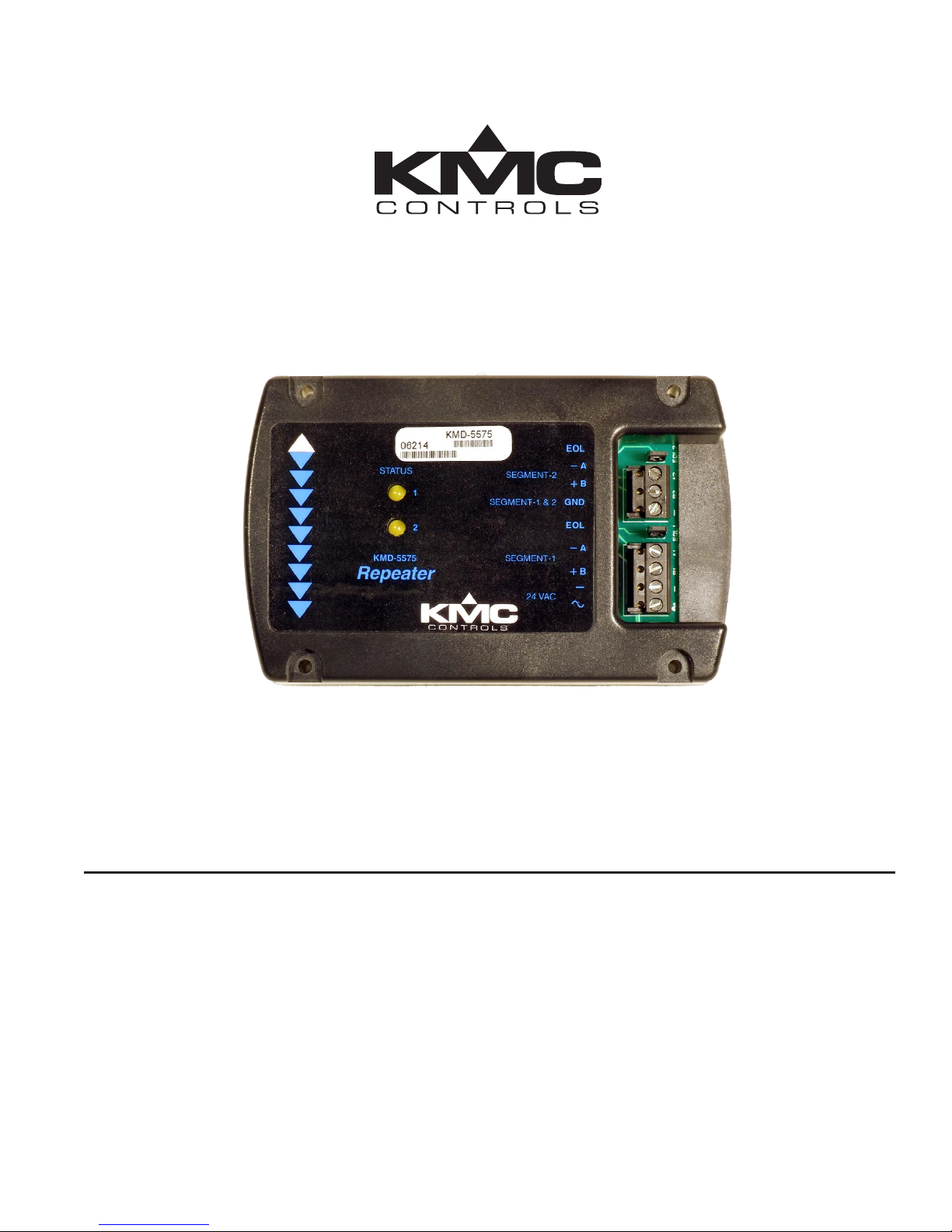
The KMC KMD-5575 Network Repeater-Isolator extends and reconditions
EIA-485 network communications as well as enabling “T” or branch networks.
The KMD-5575 is designed to recondition a degraded EIA-485 (formerly RS-485)
communication signal on a KMC KMDigital or BACnet subnetwork. Two primary
factors that cause communication signal degradation within the digital subnetwork are long subnetwork wiring lengths and the number of digital controllers
connected to the subnetwork.
A KMD-5575 is required aer every 31 consecutive controllers on KMDigital or
BACnet subnetworks (e.g., between controllers 31 and 32) or if the cumulative
wiring distance exceeds 4,000 feet. (For smoke control applications, the maximum
total length of the EIA-485 network cable, including all repeaters, is 4,000 feet.)
In addition, the KMD-5575 is required for “T” or branch network wiring congurations (see Illustration 4 ).
Illustration 1 shows the major module components and their connections.
Installation
Mounting
Fasten the KMC KMD-5575 securely to a at surface inside a metal enclosure
using #6 hardware in the four mounting holes on the top and boom (see Illustra-
KMD-5575 3 Installation and Operation Guide
tion 2). For HVAC applications, KMC Controls recommends using a UL Listed
enclosed energy management equipment panel such as a KMC model HCO-1034,
HCO-1035, or HCO-1036. The HCO-1102 enclosure will hold one KMD-5575.
For smoke control applications, the controller must be mounted in a UL Listed
Fireghter’s Smoke Control Station enclosure or listed enclosure with minimum
dimensions. The minimum enclosure size is 16 x 18 x 6 inches. KMC enclosures
HCO-1034, HCO-1035, and HCO-1036 are approved for this application. See
Smoke Control Manuals 000-035-08 (BACnet) and/or 000-035-09 (KMDigital).
To maintain RF emission specications, use either shielded connecting cables or
enclose all cables in conduit.
Illustration 1—Components
Page 4

2"
Min.
2"
Min.
Next
A
Next
B
(L)
(N)
Power
Limited
Not
Power
Limited
Power
Limited
Branch
Circuit
120 VAC
15 A, 60 Hz
Controller
Provide 15 Amp Branch Circuit:
120 VAC, 60 Hz,
60°
C, Cu Wire 14 AWG
Panel Disconnect Provided by Installer
Power Limited and Non-Power
Limited wiring must be
permanently separated by 2 inches
(minimum) and shall
be
accomplished by clamping,
routing, or equivalent means
Follow all local regulations and wiring codes when installing these products
Repeater
or
Class 2 Wiring = Power Limited
Class 1 Wiring =
Not Power Limited
4.0"
3.0"
Repeater
KMD-5575
STATUS
2
1
EOL
A
B
GND
EOL
A
B
NETWORK-2
NETWORK-1
24 VAC
NETWORK-1 & 2
Illustration 2—Mounting and Wire Routing
Wiring and Terminal Blocks
Network Connections
KMD-5575 4 Installation and Operation Guide
Terminal blocks are removable for wiring convenience. Wire sizes 14–22 AWG can
be clamped into each terminal. No more than two (16 AWG) wires can be joined at
a common point.
The KMD-5575 Network Repeater-Isolator is designed to operate between network segments. Each network is connected to the respective terminals on the
module. (See Illustration 1.)
Connect the shields of the cable together at each device on that segment.
Connect the shields to an earth ground only at one end of the segment. Do NOT
connect the cable shield to the circuit/segment GND terminal on the KMD-5575.
Page 5

EOL Jumpers Installed
A
B
A
B
24 VAC
Shields Not Connected
Repeater
KMD-5575
STATUS
2
1
EOL
A
B
GND
EOL
A
B
NETWORK-2
NETWORK-1
24 VAC
NETWORK-1 & 2
Shield Grounded at One End*
Segment Y
Segment X
*Shields should be
connected to an earth
ground at only one
end of the segment
Segment Y
Segment X
Other
Controllers
Other
Controllers
~
24 VAC
A “T” or Branch
B Segment Y
A Previous Controller
B on Segment X
A Next Controller
B on Segment X
EOL Jumper
Removed
EOL Jumper
Installed
Shield Grounded*
Shields Connected
*Shields should be connected to an earth
ground at only one end of the segment
Repeater
KMD-5575
STATUS
2
1
EOL
A
B
GND
EOL
A
B
NETWORK-2
NETWORK-1
24 VAC
NETWORK-1 & 2
Repeater
KMD-5575
STATUS
2
1
EOL
A
B
GND
EOL
A
B
NETWORK-2
NETWORK-1
24 VAC
NETWORK-1 & 2
From Other
Controllers
To Other
Controllers
Segment Y
Segment X
Illustration 3 shows a repeater as it might appear connected between two network
segments at the End-of-Line (EOL) position. (See the Conguration/EOL section
for information about the EOL jumper.)
Illustration 3—Repeater at End of Line Between Two Network Segments
Illustration 4 shows a repeater connected in a single “T” or branch network conguration. (One branch is shown coming o a segment.)
KMD-5575 5 Installation and Operation Guide
Illustration 4—Repeater in a single “T” or Branch Sublan Conguration
Page 6

Illustration 5 shows repeaters connected as they might appear in a multiple “T” or
~
24 VAC
A “T” or Branch
B Segment Y
A Previous Controller
B on Segment X
~
24 VAC
A “T” or Branch
B Segment Z
EOL Jumper
Removed
~
24 VAC
A “T” or Branch
B Segment W
EOL Jumper
Installed
Shield Grounded*
A Next Controller
B on Segment X
EOL Jumper
Removed
EOL Jumper
Installed
Shield Grounded*
Shields Connected
*Shields should
be connected to
an earth ground
at only one end
of the segment
(Other Segment X Controllers)
(Other Segment X Controllers)
Repeater
KMD-5575
STATUS
2
1
EOL
A
B
GND
EOL
A
B
NETWORK-2
NETWORK-1
24 VAC
NETWORK-1 & 2
Repeater
KMD-5575
STATUS
2
1
EOL
A
B
GND
EOL
A
B
NETWORK-2
NETWORK-1
24 VAC
NETWORK-1 & 2
Repeater
KMD-5575
STATUS
2
1
EOL
A
B
GND
EOL
A
B
NETWORK-2
NETWORK-1
24 VAC
NETWORK-1 & 2
Shields Connected
EOL Jumper
Removed
EOL Jumper
Installed
Shield Grounded*
Shields Connected
Repeater
KMD-5575
STATUS
2
1
EOL
A
B
GND
EOL
A
B
NETWORK-2
NETWORK-1
24 VAC
NETWORK-1 & 2
Repeater
KMD-5575
STATUS
2
1
EOL
A
B
GND
EOL
A
B
NETWORK-2
NETWORK-1
24 VAC
NETWORK-1 & 2
Repeater
KMD-5575
STATUS
2
1
EOL
A
B
GND
EOL
A
B
NETWORK-2
NETWORK-1
24 VAC
NETWORK-1 & 2
Other
Controllers
Other
Controllers
From Other
Controllers
To Other
Controllers
Segment Y
Segment X Segment X
Segment Z Segment W
branch network conguration. (Three branches are shown coming o a segment.)
KMD-5575 6 Installation and Operation Guide
Illustration 5—Repeaters in a multiple “T” or Branch Sublan Conguration
Page 7

EIA-485 terminals are used for connections to a network of controllers. Refer to
this checklist of best practices:
◆ Connect the shields of the cable together at each device. Do not connect the
cable shield to the circuit GND terminal on the KMD-5575.
◆ Connect the shields to a good earth ground at only one end of the segment;
tape back the shield ground at the other end.
◆ Use a KMC KMD-5575 repeater aer every 31 controllers or if the cable length
exceeds 4,000 feet (1,220 meters). Generally, use no more than four repeaters per
EIA-485 (KMDigital or BACnet) network. (For smoke control applications, the
maximum total length of the EIA-485 network cable, including all repeaters, is
4,000 feet.)
◆ If the repeater is at an end-of-line position, refer to Illustration 3 and the “Con-
guration/EOL” section. The end-of-line connection will have only one wire
aached to the A and B terminals.
◆ For reliable operation, use Belden cable model #82760 or equivalent (18-gauge,
twisted, shielded, 50 picofarads or less) for all network terminal block
connections.
◆ Connect the nodes of the network in a daisy-chain arrangement:
Connect the • A terminal in parallel with all other A terminals.
Connect the
• B terminal in parallel with all other B terminals.
◆ “Star” networks (three or more conductors under the A and B terminals) are not
recommended. “T” networks can accomplish the same goal.
◆ Place a KMC KMD-5567 surge suppressor in the cable run where it exits a build-
ing.
For smoke control applications, the maximum total length of the MS/TP netw
cable, including all repeaters, is 4,000 feet. The MS/TP communications network is
supervised in smoke control applications, and the ground fault impedance value
for the circuit is 0 ohms. For specic information on smoke control systems, see
Smoke Control Manuals 000-035-08 (BACnet) and/or 000-035-09 (KMDigital).
Configuration/EOL
Prior to operating the KMC KMD-5575 Network Repeater-Isolator Module, you
may need to congure the module for an End-of-Line (EOL) termination. See Il-
lustrations 3 through 5.
If the module is connected to the network segment in an end-of-line position (only
one set of wires connected to the terminal—refer to “Network Connections” section), place the EOL jumper in the “On” (shorted) position. If the module is not
connected in an end-of-line position (two sets of wires connected to the terminal),
then leave the jumper in the default “O” position.
Power Connection
Before connecting power, make certain all connections and EOL jumper positions
are complete and correct. Connect a KMC Controls 24 VAC Class-2 (power limited) transformer of the appropriate size to the two power connections on the lower
terminal strip. Connect the ground side of the transformer to the – terminal and
the AC phase to the ~ (phase) terminal. See Illustration 3.
ork
For smoke control applications, the KMC XEE-6112-100 transformer is required.
See Smoke Control Manuals 000-035-08 (BACnet) and/or 000-035-09 (KMDigital)
for smoke control application information.
KMD-5575 7 Installation and Operation Guide
Page 8

Indicators and Operation
The module will power up when 24 VAC is applied. No power switches are used
with this device. Once connected and powered up, the module operates automatically and requires no user intervention.
Two Status LEDs ash to indicate communications activity on the corresponding
network. The upper LED monitors Network 1 connected to the lower bank, and
the lower LED monitors Network 2 connected to the upper bank.
Accessories
Connectors and Fuses
902-602-04 Replacement three-pin removable terminal block
031-602-02 Replacement four-pin removable terminal block
HPO-0063 Replacement two-pin jumper
Enclosures
HCO-1102 Steel control enclosure, 10.1 x 2.4 x 7.1 inches
HCO-1034 Energy management equipment enclosure 16 x 18 x 6"
HCO-1035 Energy management equipment enclosure 20 x 24 x 6"
HCO-1036 Energy management equipment enclosure 24 x 36 x 6"
NOTE: For smoke control applications, the controller must be mounted in a UL
Listed FSCS enclosure or listed enclosure with minimum dimensions.
See Smoke Control Manuals 000-035-08 (BACnet) and/or 000-035-09
(KMDigital) for smoke control application information.
Power Transformers
XEE-6111-40 Transformer, 120-to-24 VAC, 40 VA, single-hub
XEE-6112-40 Transformer, 120-to-24 VAC, 40 VA, dual-hub
XEE-6112-100 Transformer, 120-to-24 VAC, 96 VA, dual-hub (required in
smoke control applications)
Specifications
Supply Voltage 24 volts AC (–15%, +20%), 60 Hz, 3 VA, Class 2 only
NOTE: All circuits, including supply voltage, are power limited. AC power is
non-supervised in smoke control applications.
Baud Rate
Connections Removable screw terminal blocks, wire size 14–22 AWG
Network Wiring Belden 82760 or equivalent, shielded, twisted, 18 AWG,
5.5 ohms per 1,000 feet and ≤ 51 pF/foot (network
connections are supervised in smoke control applications)
Material Black ABS
Size 5.31 x 3.38 inches (134.9 x 85.8 mm)
Weight 2.5 oz. (71 grams)
Regulatory UL 916 Energy Management Equipment listed; UL 864
Smoke Control Equipment listed (UUKL)—see Smoke
Control Manuals 000-035-08 (BACnet) and/or 000-035-09
(KMDigital) for smoke control application information
Ambient Limits
Operating 32 to 120° F (0 to 49° C)
Shipping –40 to 140° F (–40 to 60° C)
Humidity 0 to 95% RH, non-condensing
KMD-5575 8 Installation and Operation Guide
9,600 to 38,400
 Loading...