

Page 1
Installation and Operation Guide
KMD-5220
Input Module
For use with KMD-5210
Revision C
883-019-05C
Page 2

KMC Controls
Important notices ©2013, KMC Controls, Inc.
WinControl, NetSensor, and the KMC logo are registered trademarks of KMC
Controls, Inc.
TotalControl, BACstage, and FullBAC are trademarks of KMC Controls, Inc.
All rights reserved. No part of this publication may be reproduced, transmitted,
transcribed, stored in a retrieval system, or translated into any language in any
form by any means without the written permission of KMC Controls, Inc.
Printed in U.S.A.
Disclaimer The material in this manual is for information purposes only. The contents and
the product it describes are subject to change without notice. KMC Controls, Inc.
makes no representations or warranties with respect to this manual. In no event
shall KMC Controls, Inc. be liable for any damages, direct or incidental, arising
out of or related to the use of this manual.
KMC Controls
P. O . Box 497
19476 Industrial Drive
New Paris, IN 46553
U.S.A.
TEL: 1.574.831.5250
FAX: 1.574.831.5252
E-mail: info@kmccontrols.com
Revision C2
Page 3

KMD–5220 Installation and Operation
Contents
Section 1
Introduction
Specifications ........................................................................................................................ 5
Accessories ............................................................................................................................ 7
Safety considerations ..........................................................................................................8
Section 2
Installation
Mounting .............................................................................................................................. 9
Planning for input modules ............................................................................................... 9
Module installation ........................................................................................................... 10
Connecting inputs ............................................................................................................. 11
Section 3
Operation
Status LED .......................................................................................................................... 13
Auxiliary power fuse ........................................................................................................ 14
Power On/Off .................................................................................................................... 14
Maintenance ....................................................................................................................... 14
Revision C 3
Page 4

KMC Controls
Revision C4
Page 5

SECTION 1
Introduction
This section provides an introduction to the KMD-5220 Input
Module. You will also find Safety Considerations included in this
section. Review this material in its entirety before installing or
operating the module.
The KMD-5220 Input Module is an auxiliary device for the KMD-5210 LAN
Controller. The Input Module takes up to 16 separate inputs and processes the
information for input to the LAN Controller. The module can process active,
passive, current loop or pulse inputs.
The module also provides a fused, auxiliary power terminals for connecting up
to 6 external transducers.
The KMD-5220 Input Module is designed to accept digital or analog inputs from
active and passive sensor and control devices and process those inputs for use
by the KMD-5210 LAN Controller.
Specifications Input
Universal inputs 16
Key features Each input software selectable for analog or digital
Connector Removable screw terminal block, wire size
Pull–up resistors Selected by moveable jumper for 1KΩ, 10KΩ
Input impedance 1KΩ or 10KΩ for 1KΩ or 10KΩ pullup
Overvoltage protection 24 volts AC, continuous
Input range 0–5 volts DC
Weight 16 ounces (454 grams)
Indicators Status LED flashes when card is accessed
Ambient Limits
Operating 0 to 120°F (–18 to 49°C)
Shipping –40 to 140°F (–40 to 60°C)
Humidity 0–95% RH, non-condensing
signals. Standard and custom units of measure.
Pull-up resistors for switch contacts and other
unpowered equipment.
AWG
14–22
4-20mA or none.
250Ω for 4–20 mA
100KΩ without jumper
Revision C 5
Page 6

Introduction
A
B
C
E
D
F
Specifications
KMC Controls
Regulatory UL 916 Energy Management Equipment listed
CE compliant
FCC Class B, Part 15, Subpart B
SASO PCP Registration KSA R-103263
Dimensions
Table 1-1 Dimensions
A B C D E F Height (not shown)
4.50 in. 9.00 in. 4.00 in. 0.25 in. 6.00 in. 1.50 in.
114 mm 229 mm 102 mm 6 mm 152 mm 38 mm
0.98 in.
25 mm
6
Revision C
Page 7

KMD–5220 Installation and Operation
Accessories
Ribbon cables
KMD-5660 6 inch (15 cm) ribbon cable
KMD-5668 9 inch (23 cm) ribbon cable
KMD-5661 14 inch (36 cm) ribbon cable
KMD-5662 19 inch (48 cm) ribbon cable
KMD-5663 24 inch (61 cm) ribbon cable
Introduction
Accessories
Revision C
7
Page 8

Introduction
Danger
Warning
Caution
Note
Detail
Safety considerations
KMC Controls
Safety
considerations KMC Controls assumes the responsibility for providing you a safe product and
safety guidelines during its use. Safety means protection to all individuals who
install, operate, and service the equipment as well as protection of the
equipment itself. To promote safety, we use hazard alert labeling in this manual.
Follow the associated guidelines to avoid hazards.
Danger represents the most severe hazard alert. Bodily harm or death will
occur if danger guidelines are not followed.
Warning represents hazards that could result in severe injury or death.
Caution indicates potential personal injury or equipment or property damage
if instructions are not followed.
Notes provide additional information that is important.
Provides programing tips and shortcuts that may save time.
8
Revision C
Page 9

KMD–5220 Installation and Operation
SECTION 2
Installation
This section provides important instructions and guidelines for
installing the KMD-5220 Input Module. Carefully review this
information before installing a KMD-5220 module.
Mounting Mount KMD-5220 input modules and the KMD-5210 to which they are
connected inside of a metal enclosure. KMC Controls recommends using a ULapproved Enclosed Energy Management Equipment Panel such as a KMC
model HCO–1034, HCO–1035 or HCO–1036. Use the two mounting holes on
each side of the module to fasten it securely to a flat surface with #6 or #8
hardware. See
dimensions. To maintain RF emissions specifications, use either shielded
connecting cables or enclose all cables in conduit.
Dimensions on page 6 for mounting hole locations and
Installation
Mounting
Planning for input modules
To connect inputs devices to a KMD-5210 controller, use one or more KMD-5220
input modules. The KMD-5210 controller includes eight universal I/O ports for
up to eight KMD-5220 input modules, eight KMD-5221 output modules or any
combination of up to eight modules.
Each module connects to the controller using a flat ribbon cable. Connect the
first KMD-5220 input module to connector
modules from left to right.
I/O Card 1; continue adding input
Revision C
Illustration 2-1 Input module connections
9
Page 10

Installation
Note
Caution
Pin 1 edge
(Red)
I/O port
connection
Input/Output card
connection
Fold gently
Pin 1 edge
(Red)
Fold back
Module installation
Module
KMC Controls
installation
1. Position and mount the modules near the KMD-5210 to which it will
connect. Input modules connect at position I/O Card #1.
2. Connect the ribbon cable to the KMD-5210 LAN Controller. Estimate the
required cable length and select from one of the cables from KMC Controls.
See Ribbon cables
on page 7 in the Accessories section.
Observe the orientation of the cable header. If the pin 1 edge is reversed, the
controller will not communicate with the module.
Illustration 2-2 Ribbon cable orientation
3. Connect the other end of the ribbon cable to the input module. You may
find it necessary to fold the cable to properly route it to the module.
To accommodate turns, fold the cable gently to change direction. To make a fold,
overlay the cable at a right angle and press gently until the cable holds the fold
as shown in
Illustration 2-3.
10
Illustration 2-3 Ribbon cable fold
Do not crimp the cable in a tight fold. This may result in separation of cable
strands and result in unreliable operation of the module.
4. Connect input devices to the modules.
Revision C
Page 11

KMD–5220 Installation and Operation
Connecting
Installation
Connecting inputs
inputs
The controllers include 16 universal inputs. Each input can be configured with
software to receive either analog or digital signals. By using the optional pullup
resistors, either passive or active devices may be connected to the inputs. For
additional information, see
Appendix C, Connecting Inputs and Outputs in the
WinControl XL Plus manual.
Pull–up resistors
For passive input signals, such as thermistors or switch contacts, use a pull-up
resistor. For KMC thermistors and most other applications place the moveable
jumper in the
10K position. For 1kΩ platinum RTD sensors, place the moveable
jumper in the 1K position.
Pulse inputs
Connect pulse inputs under the following conditions:
◆ Use only the input module installed in the card #1 position for pulse inputs.
◆ If the pulse input is a passive input such as switch contacts, then place the
input pull-up in the 10K position.
◆ If the pulse is an active voltage (up to a maximum of +5 volts DC ), then
place the input pull-up jumper in the None position.
4–20 mA inputs
To use a 4–20 current loop input, place the moveable jumper in the 4-20mA
position. This places a 250 ohm resistor across the input terminals which will
convert the current input to a voltage which can be read by the controller’s
analog-to-digital converter.
Revision C
11
Page 12
Installation
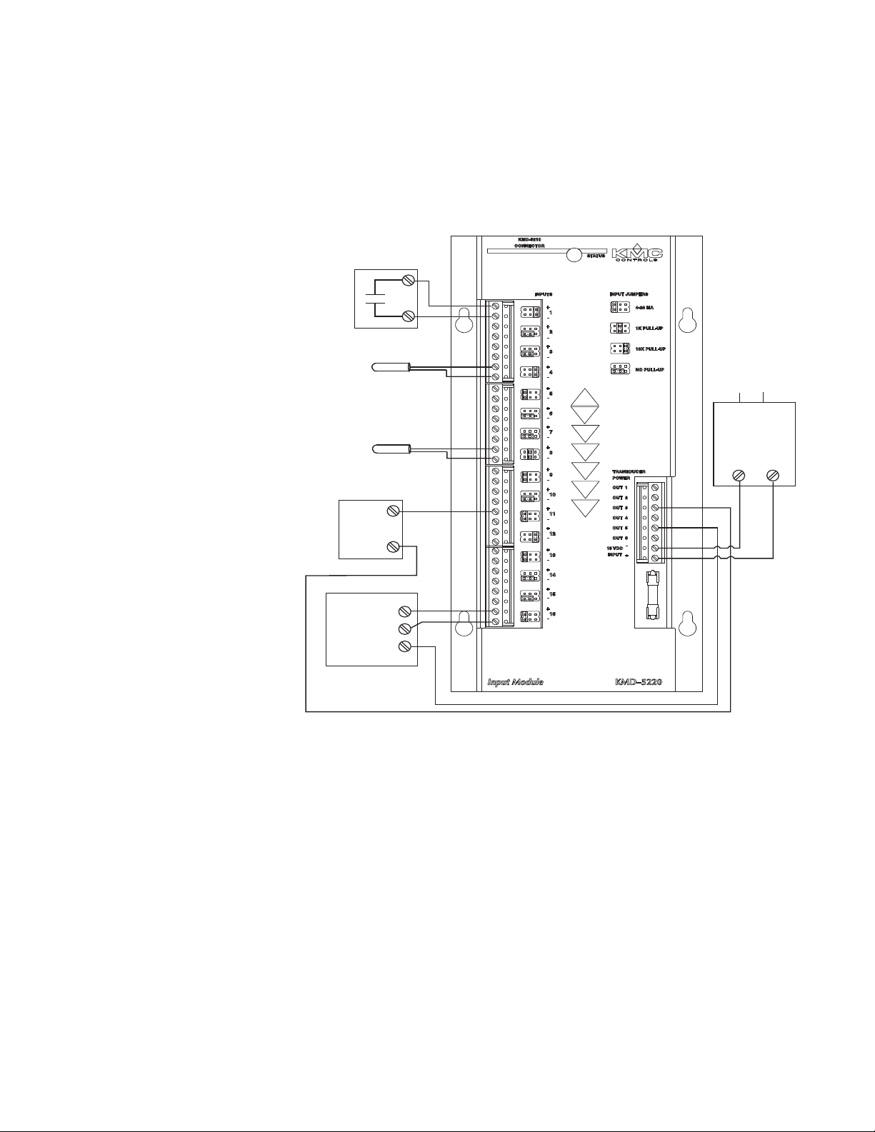
4-20 Sig
(–) Com
(+) Pwr
(–)
(+)
24 VAC
Regulated
DC Power
Supply
(–)
(+)
10K thermistor
1K platinum RTD
4–20 mA
transmitter
4–20 mA
transmitter
Switch
contacts
Connecting inputs
KMC Controls
Ground terminals
Ground terminals (-) are located next to each input terminal. Up to two wires,
size 12–22 AWG, can be clamped into each ground terminal. If more than two
wires must be joined at a common point, use an external terminal strip to
accommodate the additional wires.
12
Illustration 2-4 Typical input configurations
Auxiliary transducer power
The KMD-5220 Input Module has provisions for supplying power to six external
transducers. These terminals are located on the lower right side of the module.
The maximum output of all six outputs cannot exceed 1 ampere or the fuse will
open.
The negative power supply terminal is common to the analog input grounds.
For example, on a two–wire device the power is drawn from one of the six
outputs and the return goes to one of the inputs terminals. On a three–wire
transducer, the input negative can be run to the transducer to provide a power
supply reference. See
Illustration 2-4 for example of input connections.
Revision C
Page 13

KMD–5220 Installation and Operation
Status LED
Auxiliary
power fuse
SECTION 3
Operation
This section provides general operating instructions for your
KMD-5220 input module. Carefully review this information before
operating the module.
Once the input module is wired and powered up, operation is automatic.
Operation
Status LED
Illustration 3-1
Status LED The status LED at the top of the module will illuminate when the module is
communicating with the LAN controller too which it is connected. Under
normal operation the LED blinks at a regular rate. The LED glows steady until
the LAN controller to which it is connected is programmed in HCM and at least
one input is configured with WinControl XL Plus.
Revision C
13
Page 14

Operation
Caution
Auxiliary power fuse
Auxiliary power
KMC Controls
fuse
If the output of all six auxiliary power terminals exceeds 1 ampere, the fuse will
open. The fuse must be replaced with a fuse of equivalent rating.
Do not use a larger rated fuse as this may result in damage to the KMD-5220.
Power On/Off The input module does not use an On/Off switch or a power jumper. After the
module is connected to a LAN controller and the LAN controller is powered, the
module is also powered.
Maintenance The KMD-5220 does not require routine maintenance. If cleaning is required, wipe
soft, damp cloth and mild soap.
with a
14
Revision C
 Loading...