

Page 1
Installation and
Operation Guide
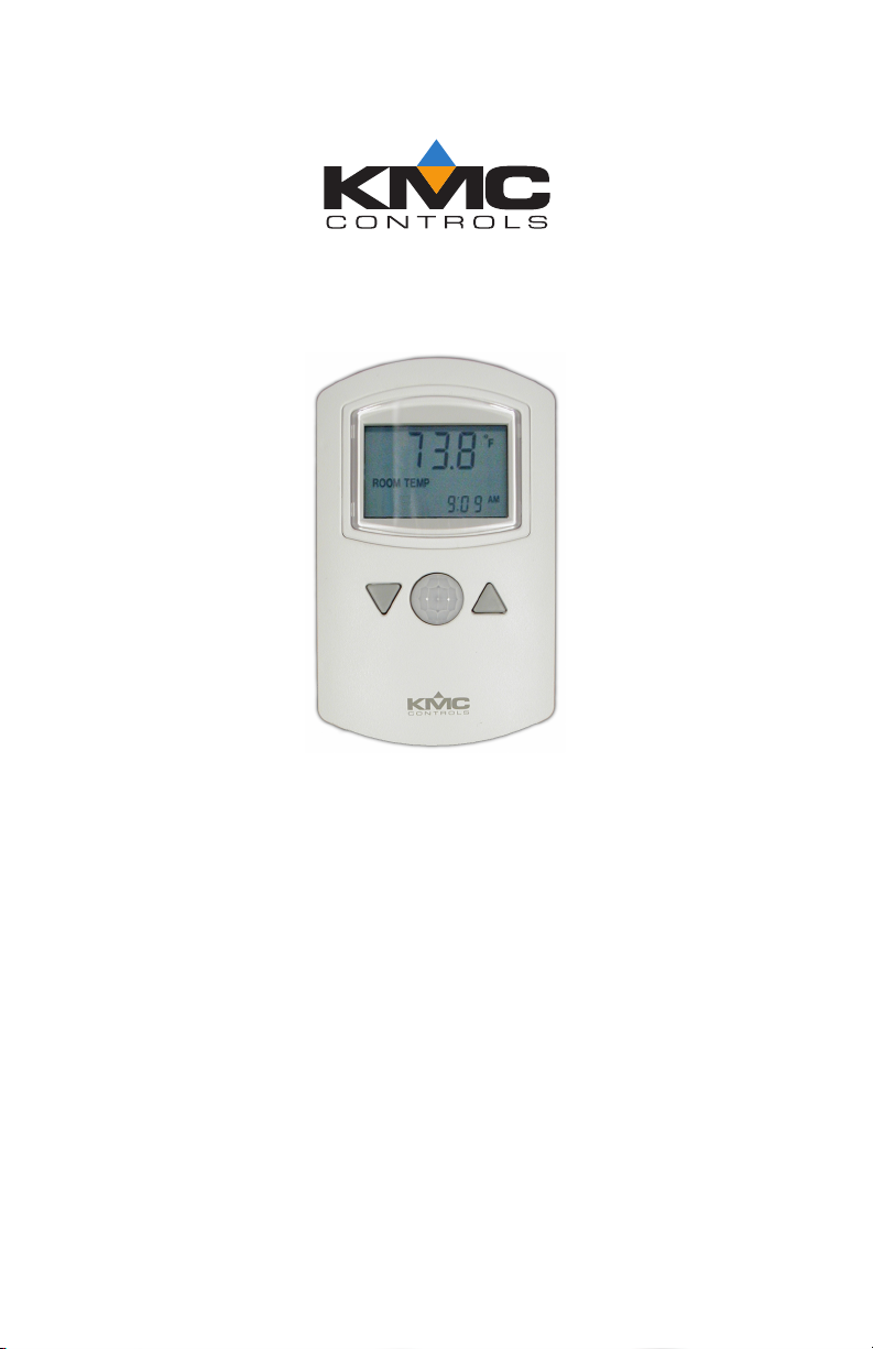
NetSensor
KMD-1261 and KMD-1281
Motion, temperature
and humidity sensors
®
Contents
Specifications ............................................................... 2
Network cable preparation ........................................... 5
Rough-in preparation ................................................... 6
Installing the NetSensor ................................................ 7
Operation .................................................................... 8
Maintenance ................................................................ 9
903-019-10ARevision A
Page 2

KMC Controls
Specifications
Display LCD, 4-character, 7-segment,
in. high. (temperature)
0.375
Compatibility KMD-5800 series controllers
KMD-7000 series controllers
BAC-5800 series BACnet controllers
BAC-7000 series BACnet controllers
Controller Connection
Connector type RJ–12 connects data and power to
compatible controllers
Cable length Maximum 75 feet (22.9 meters)
PC port Four-pin connector for service
connection to software tools
Power 5 volts DC supplied by the connected
controller
Mounting Surface mount directly to any flat
surface or to a 2 x 4 inch or 4 x 4 inch
handy-box. Mounting on a 4 x 4 inch
box requires a mounting backplate.
Weight 2.8 ounces (80 grams)
Material Light almond or white plastic
Revision A2
Page 3

NetSensor Installation and Operation
Accessories
Mounting backplate
Almond 4 x 4 inch HMO-1161
White 4 x 4 inch HMO-1161W
Gasket HPO-1161
Replacement Allen screws HPO-0044 (package of 10)
Network plenum cables with connectors
25 feet (7.6 meters) KMD-5690
50 feet (15.2 meters) KMD-5691
75 feet (22.9 meters) KMD-5692
Sensor Accuracy, KMD-1261
Typ e Thermistor
Accuracy ±0.36° F (±0.2° C)
Resistance 10,000 at 77° F (25° C)
Operating range 48° to 96° F (8.8° to 35.5° C)
Sensor Accuracy, KMD-1281
Typ e CMOS
Humidity
Range 0 to 100% Relative humidity
Accuracy at 25°C ±2% from 10–90% Relative humidity
Response time Less than or equal to 4 seconds
Tem pe ra t ur e
Accuracy ±0.9° F (±0.5° C) Offset from
40 to 104° F
(4.4 to 40.0° C) Offset is adjusted
through configuration software
Resolution ±0.1°F (±0.1° C)
Operating range 36 to 120° F (2.2 to 48.8° C)
Response time 5 to 30 seconds
Environmental Limits
Operating Temperature 34° to 125° F (1.1 to 51.6° C)
Shipping –40° to 140° F (–40°C to 60° C)
Humidity 0 to 95% Relative humidity
non-condensing
Revision A 3
Page 4

Dimensions
A
C
D
E
B
F
KMC Controls
AB CDE F
3.25 in. 5.16 in. 2.58 in. 3.25 in. 0.87 in. 1.07 in.
83 mm 131 mm 66 mm 83 mm 22 mm 27 mm
Models
Temperature only
Almond KMD-1261
White KMD-1261W
Temperature and humidity
Almond KMD-1281
White KMD-1281W
Revision A4
Page 5

NetSensor Installation and Operation
55
°
10 m
32.8 ft
10 m
32.8 ft
X
0°
10 m
32.8 ft
10 m
32.8 ft
0°
46.5
°
Y
Top view
Side view
RJ-12
Motion sensor range 33 feet (10 meters)
Network cable preparation
Connecting a NetSensor to a controller requires a six-wire cable with
RJ-12 connectors on each end. KMC plenum-rated preassembled
cables are recommended. Cables made to length must meet the
following requirements:
◆ Cable length must be no longer than 75 feet (22.9 meters).
◆ Cable conductors must be no smaller than #24 AWG.
◆ Cable insulation must meet local building codes.
◆ Connectors must be appropriate for the cable in use and are
installed following the connector manufacturers instructions.
Cable details
Revision A 5
Page 6

KMC Controls
Caution
RJ-12
cable
Allen
screws
Mounting
base
Rough-in preparation
To prevent mounting screw heads from touching the circuit
board in the NetSensor, use only the mounting screws
supplied by KMC Controls. Using screws other than the
type supplied will damage the NetSensor.
Complete rough-in wiring at each sensor location prior to sensor
installation. This includes the following.
◆ Routing the network cable from the NetSensor to a controller.
◆ If required, installing the appropriate backplate. See Accessories
on page 3 for model numbers.
NetSensor mounting details
Revision A6
Page 7

NetSensor Installation and Operation
Turn clockwise to
remove from base.
Installing the NetSensor
1. Turn the Allen screws in the base of the NetSensor clockwise
until they clear the cover. Swing the sensor away from the
mounting base to remove it.
Mounting screws
2. Route the RJ-12 cable through the mounting base.
3. Fasten the mounting base directly to a 2 x 4 inch outlet box or a
backplate with the Allen screws toward the floor.
4. Insert the RJ-12 cable coming from the base into the NetSensor.
5. Place the top of the NetSensor over the top of the mounting base
and swing it down over the Allen screw brackets. Be careful not
to pinch any wiring.
6. Back the Allen screws out of the brackets until they engage the
NetSensor cover and hold it in place.
Revision A 7
Page 8

KMC Controls
Setpoint
Operation
The following sections describe the controls and indicators found on
the NetSensor.
Display The temperature display contains four 0.375-inch, 7-segment
LCD digits that are visible across a normal size office. The display
provides time, temperature and on the KMD-1281 humidity
readouts. Room temperature is displayed until either setpoint button
is pressed and then the display changes to setpoint mode.
Controls Models KMD-1261 and KMD-1281 include eight push
buttons; six of which (button 1 and buttons 3-7) are user
programmable. The actual operation of the programmable buttons
depend upon the program in the controller to which the NetSensor is
connected.
NetSensor buttons
The arrow buttons adjust the programmed values up or down. Values
can be changed for all programmed buttons except the setpoint as
follows:
1. Press the button for the desired function.
2. Adjust the value up or down.
Setpoint Pressing either the up or down arrow buttons changes
the display from room temperature mode to setpoint mode. Each
additional time a setpoint button is pressed and released changes the
setpoint up or down.
Auxiliary function These NetSensors do not have auxiliary wires
found on earlier models. Press buttons 5 and 7 together and then
press an up arrow or down arrow button to change the auxiliary
function.
Revision A8
Page 9

NetSensor Installation and Operation
Programming instructions
Programming instructions for NetSensors are included in Help
supplied with WinControlXL, BACstage, and TotalControl.
Maintenance
Remove dust as necessary from holes in top and bottom. Clean the
display and motion sensor cover with a soft, damp cloth and mild
soap.
Revision A 9
Page 10

KMC Controls
Important notices
The KMC logo, WinControlXL and NetSensor are registered
trademarks of KMC Controls, Inc.
TotalControl and BACstage are trademarks of KMC Controls, Inc.
©2012, KMC Controls, Inc.
All rights reserved. No part of this publication may be reproduced,
transmitted, transcribed, stored in a retrieval system, or translated
into any language in any form by any means without the written
permission of KMC Controls, Inc.
Printed in U.S.A.
Disclaimer
The material in this manual is for information purposes only. The
contents and the product it describes are subject to change without
notice. KMC Controls, Inc. makes no representations or warranties
with respect to this manual. In no event shall KMC Controls, Inc. be
liable for any damages, direct or incidental, arising out of or related to
the use of this manual.
KMC Controls. Inc.
19476 Industrial Drive
New Paris, IN 46553
TEL: 1.574.831.5250
FAX: 1.574.831.5252
E-mail: info@kmccontrols.com
Revision A10
 Loading...