

Page 1
Installation and
Operation Guide
NetSensor
KMD-1162
Temperature sensor
®
Contents
Specifications ............................................................... 2
Network Cable Preparation ..........................................4
Rough-in preparation ................................................... 5
Installing the NetSensor ................................................ 5
Operation .................................................................... 6
Maintenance ................................................................ 7
Revision A
903-019-03ARevision A
Page 2

KMC ControlsKMD–1162 Installation and Operation
Specifications
Display LCD, 2-character, 7-segment,
in. high.
056.
Compatibility KMD-5800 series controllers
KMD-7000 series controllers
BAC-5800 series BACnet controllers
BAC-7000 series BACnet controllers
Connection
Connector type RJ–12 connects data and power to
compatible controllers
Cable length Maximum 75 feet (22.9 meters)
PC port Four-pin connector for service
connection to software tools
Power 5 volts DC supplied by connected
controller
Mounting Surface mount directly to any flat
surface or to a 2 x 4 inch or 4 x 4 inch
handy-box. Mounting on a 4 x 4 inch
box requires a mounting backplate.
Weight 2.8 ounces (80 grams)
Material Light almond or white plastic
Environmental Limits
Shipping temperature -40 to 140° F (-40 to 60° C)
Humidity 0–95% relative humidity
non-condensing
Accessories
Mounting backplate, 4 x 4 inch
Almond HMO–1161
2
Page 3
KMD–1162 Installation and Operation
A
C
D
E
B
White HMO–1161W
Replacement allen screw HPO–0044
Network cables
25 feet (7.6 meters) KMD–5690
50 feet (15.2 meters) KMD–5691
75 feet (22.9 meters) KMD–5692
Interface Cable KMD–5624
Gasket HPO–1161
Sensor type and accuracy
Typ e 10k thermistor
Accuracy ±2° F (±1.1° C)
Operating range 47 to 97° F (8 to 36° C)
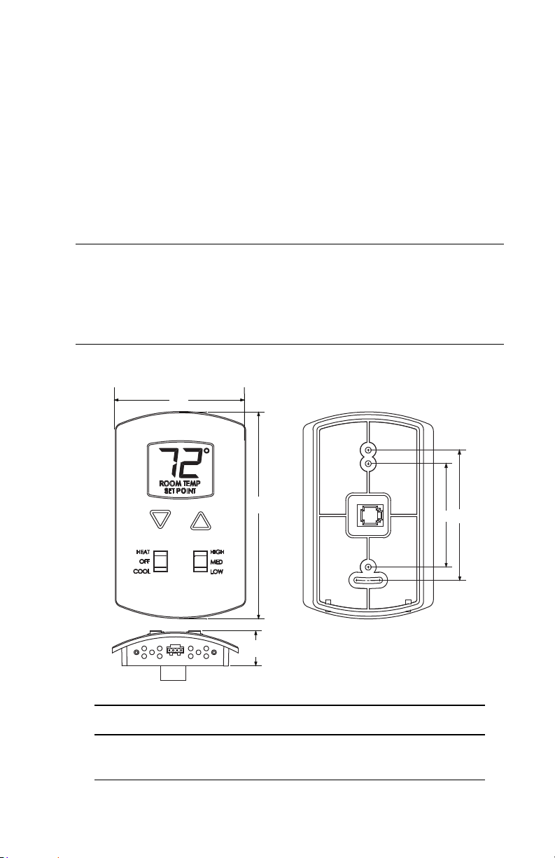
Dimensions
ABCDE
3.25 in. 5.16 in. 2.58 in. 3.25 in. 0.87 in.
83 mm 116 mm 66 mm 83 mm 22 mm
3
Page 4

KMC ControlsKMD–1162 Installation and Operation
RJ-12
Models
Almond KMD-1162-10
White KMD-1162W10
Network Cable Preparation
Connecting a NetSensor to a KMC controller requires a six-wire cable
with RJ-12 connectors on each end. Use either the KMC Controls
ready-to-use cables or make cables to length when the NetSensor is
installed. Cables made to length must meet the following
requirements:
◆ Cable length is no longer than 75 feet (22.9 meters).
◆ Use cable with #24 AWG size conductors.
◆ Cable insulation must meet local building codes. Plenum rated
cable is recommended.
◆ Connectors are appropriate for the cable in use and are installed
following the connector manufactures instructions.
Cable Details
4
Page 5

KMD–1162 Installation and Operation
Caution
RJ-12
cable
Allen
screws
Mounting
base
Turn clockwise to
remove from base.
Rough-in preparation
Complete rough-in wiring at each sensor location prior to sensor
installation. This includes the following.
◆ Route the network cable from the NetSensor location to the
controller to which it will connect.
◆ If required, install the appropriate mounting backplate. See
Accessories
on page 2 for model numbers.
NetSensor mounting backplate
To prevent mounting screw heads from touching the circuit
board in the NetSensor, use only the mounting screws
supplied by KMC Controls. Using screws other than the
type supplied will damage the NetSensor.
Installing the NetSensor
1. Turn the Allen screws in the base of the NetSensor clockwise
until they clear the cover. Swing the sensor away from the
backplate to remove it.
Allen screws
2. Route the RJ-12 cable through the mounting base.
5
Page 6

KMC ControlsKMD–1162 Installation and Operation
Setpoint
buttons
Mode
Fan speed
3. Fasten the mounting base to the backplate or the outlet box with
the Allen screws toward the floor.
4. Insert the RJ-12 cable coming from the base into the NetSensor.
5. Place the top of the NetSensor over the top of the mounting base
and swing it down over the Allen screw brackets. Be careful not
to pinch any wiring.
6. Back the Allen screws out of the brackets until they engage the
NetSensor cover and hold it in place.
Operation
The following sections describe the controls and indicators found on
the NetSensor.
NetSensor button functions
Display
The display includes two 7-segment LCD digits that are visible across
a normal size office. Room temperature is displayed until either
setpoint button is pressed and then the display changes to setpoint
mode.
If the temperature remains out of the temperature operating range for
more than 45 seconds, the KMD–1162 displays a set of dashes (—).
The NetSensor also sends 0 to the controller if the temperature is
below 47 degrees Fahrenheit (8 degrees Celsius) and 120 if the
temperature is above 97 degrees Fahrenheit (36 degrees Celsius).
6
Page 7

KMD–1162 Installation and Operation
Changing the setpoint
Pressing either the up or down setpoint buttons changes the display
from room temperature mode to setpoint mode. Pressing either
button once displays the current setpoint for three seconds; each
additional press increments or decrements the setpoint temperature
by one degree Fahrenheit.
Backlight
When either setpoint button is pressed the backlight turns on and
remains on for 10 seconds after the last button is released.
Programming instructions
Programming instructions for NetSensors are included in Help
supplied with WinControlXL, BACstage, and TotalControl.
Maintenance
Remove dust as necessary from holes in top and bottom. Clean the
display with soft, damp cloth and mild soap.
7
Page 8

KMC ControlsKMD–1162 Installation and Operation
Important notices
The KMC logo, WinControlXL and NetSensor are registered
trademarks of KMC Controls, Inc.
TotalControl and BACstage are trademarks of KMC Controls, Inc.
©2012, KMC Controls, Inc.
All rights reserved. No part of this publication may be reproduced,
transmitted, transcribed, stored in a retrieval system, or translated
into any language in any form by any means without the written
permission of KMC Controls, Inc.
Printed in U.S.A.
Disclaimer
The material in this manual is for information purposes only. The
contents and the product it describes are subject to change without
notice. KMC Controls, Inc. makes no representations or warranties
with respect to this manual. In no event shall KMC Controls, Inc. be
liable for any damages, direct or incidental, arising out of or related to
the use of this manual.
KMC Controls. Inc.
19476 Industrial Drive
New Paris, IN 46553
TEL: 1.574.831.5250
FAX: 1.574.831.5252
E-mail: info@kmccontrols.com
8
 Loading...