

Page 1

HPO-6700 Series Output Override Boards
Installation Guide
CONTENTS
Introduction .............................................. 1
Conquest Controllers/Modules ..................... 2
Older "Plastic" Case Controllers ................... 3
Older "Metal" Case Controllers ..................... 4
Wiring ...................................................... 4
Grounds Versus Switched Commons ............. 6
Maintenance ............................................. 6
Important Notices ...................................... 6
INTRODUCTION
Hand-Off-Auto
Switch (Not
Included with
HPO-670x-1)
LED Output
Indicator
Manual/Hand
Output Adjustment
(Potentiometer
on HPO-6702 and
HPO-6704)
The HPO-6704 converts a standard analog
voltage output to a 4–20 mA output while
providing an adjustable potentiometer for
override settings while in the “Hand” position.
NOTE: The HPO-6704 board supplies the
power and will not work with a 4–20
mA device that also supplies its own
power.
Each output board has a red LED indicator that
turns On when the board’s output is turned On
either manually or automatically.
Output boards have an accessible three-position
slide switch for selecting the “Hand-Off-Auto”
functions:
While in the H (“Hand” or manual On) position,
the output is manually energized, and the
controller is provided with a feedback signal to
indicate the output has been overridden.
HPO-6701
(Triac)
HPO-6702
(0–10 VDC)
HPO-6704
(4–20 mA)
HPO-6703
(NO Relay)
HPO-6705
(NC Relay)
For enhanced controller output options (such
as manual control, using large relays, or for
devices that cannot be powered directly from a
standard output), install output override boards
(in compatible controllers). The following types of
override boards are available:
The HPO-6702 enhances the analog voltage
output with a “Hand-Off-Auto” control while
providing an adjustable potentiometer for
override settings while in the “Hand” position.
The HPO-6701/6703/6705 boards are
designed to convert a binary/digital output
to a relay contact or triac output and to
provide “Hand-Off-Auto” control and feedback
functions.
While in the O (Off) position, the output is
manually de-energized, and the controller is
provided with a feedback signal to indicate the
output has been overridden.
While in the A (Auto) position, the output is
under the command of the controller.
NOTE: An HPO-670x-1 is always in auto mode
and does not have the manual slide
switch.
NOTE: HPO-6701 triac and HPO-6703/6705
relay circuits use the Switched
Common SC terminal—not the Ground
Common GND terminal.
NOTE: HPO-6701 triac outputs are for 24 VAC
only.
NOTE: Only the HPO-6701 triac and HPO-
6704 4–20 mA boards are approved
for smoke control applications. For
smoke control application information,
KMC Controls, 19476 Industrial Drive, New Paris, IN 46553 / 877.444.5622 / Fax: 574.831.5252 / www.kmccontrols.com
Page 2
see Smoke Control Manuals 000035-08 (BACnet) and/or 000-035-09
(KMDigital).
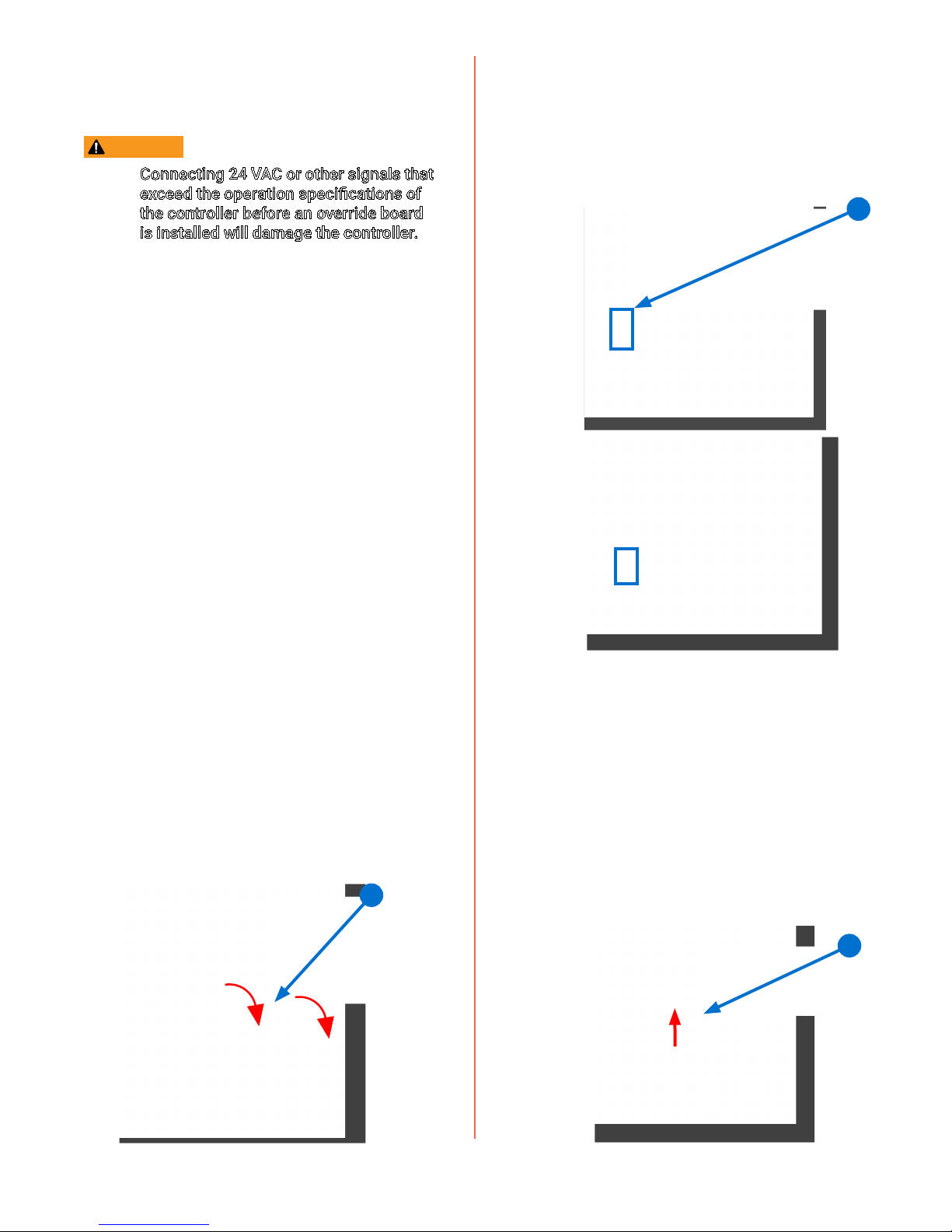
2. Pull the top edge of the (translucent black)
override board cover away from the case and
flip open the cover.
CAUTION
Connecting 24 VAC or other signals that
exceed the operation specications of
the controller before an override board
is installed will damage the controller.
For HPO-6700 series specications, see the data
sheet at kmccontrols.com.
See the sections below for installation into the
particular type of controller.
For KMC Conquest BAC-5900 series
controllers and CAN-5901 expansion modules,
see Conquest Controllers/Modules on page
2.
For older controllers with “top-mounting”
raised plastic cases (BAC-5801/5802 and
newer KMD-5801/5802s), see Older “Plastic”
Case Controllers on page 3.
For older controllers with metal (e.g., BAC-
5831, BAC-A1616BC) and older “sidemounting” plastic cases (older KMD-
5801/5802s), see Older “Metal” Case
Controllers on page 4.
CONQUEST CONTROLLERS/MODULES
These instructions apply to KMC Conquest BAC5900 series controllers and CAN-5901 expansion
modules (with a flip-open lid).
1. Disconnect the power by removing the black
power terminal block.
2
3. Remove the jumper from the slot in which the
override board will be installed.
3
NOTE: Each of the eight override slots ships
from KMC with a jumper installed on
the two pins closest to the output
terminal blocks. Only remove a jumper
if an override board will be installed.
4. Orient the override board with the HOA
selection slide switch toward the top of the
controller.
5. Slide the override board into the slot in which
the jumper was removed.
HPO-6700 Series Output Override Boards Installation Guide 2 902-019-02K
4
Page 3

6. Close the plastic cover.
7. Move the A-O-H selection switch on the
override board to the appropriate position.
NOTE: A = Automatic (upper position).
O = Off (middle position).
H = Hand/On (lower position).
NOTE: For more information about output
override boards, see the installation
guide for the HPO-6700 Series.
OLDER "PLASTIC" CASE CONTROLLERS
7
These instructions apply to controllers with
“top-mounting” raised plastic cases (e.g., BAC5801/5802 and newer KMD-5801/5802). After
installation of the boards, the existing cover is
reinstalled.
To install the HPO-6700 series override boards:
1. Disconnect the power by removing the power
jumper or terminal block.
8. Repeat Steps 3 through 7 for all other desired
boards.
9. Wire the output device to the corresponding
green (output) terminal block of the override
board. (See Wiring on page 4.)
2. Remove the cover by squeezing on both sides
of the cover and lifting it off.
3. Remove the jumper from the slot in which the
override board will be installed.
NOTE: Each of the override slots ships from
7
KMC with a jumper installed on the
two pins closest to the output terminal
blocks. Only remove a jumper if an
override board will be installed.
4. Orient the override board with the HOA
selection slide switch toward the top of the
controller.
5. Slide the override board into the slot in which
the jumper was removed.
5
4
HPO-6700 Series Output Override Boards Installation Guide 3 902-019-02K
3
2
1
Page 4

6. Set the selection switch on the override board
to the appropriate position.
NOTE: A = Automatic (upper position).
O = Off (middle position).
H = Hand/On (lower position).
7. Repeat steps 3 through 6 for all desired
boards.
8. Reinstall the cover over the boards.
9. Connect output devices to the controller
outputs. (See Wiring on page 4.)
10. Reinstall the power jumper that was removed
in Step 1.
OLDER "METAL" CASE CONTROLLERS
8
4
3
2
1
NOTE: Each of the override slots ships from
KMC with a jumper installed on the
two pins closest to the output terminal
blocks. Only remove a jumper if an
override board will be installed.
4. Orient the override board with the HOA
selection slide switch toward the outputs of
the controller.
These instructions apply to controllers with
metal (e.g., BAC-5831, BAC-A1616BC) and older
“side-mounting” plastic cases (e.g., older KMD-
5801/5802). After installation of the boards, the
existing slot cover needs to be replaced by a
raised HPO-6802 output board cover.
To install the HPO-6700 series override boards:
1. Disconnect the power by removing the power
jumper or terminal block.
2. Remove the relevant slot cover(s) by lifting the
right-hand side of the cover (within the plastic
frame) toward you.
3. Remove the jumper from the slot in which the
override board will be installed.
5. Slide the override board into the slot in which
the jumper was removed.
6. Move the A-O-H selection switch on the
override board to the appropriate position.
NOTE: H = Hand/On.
O = Off.
A = Automatic.
7. Repeat steps 3 through 6 for all desired
boards.
8. Remove the necessary label slots for each
board location in the HPO-6802 output board
cover (purchased separately).
9. Snap the HPO-6802 cover over the boards.
10. Connect output devices to the controller
outputs. (See Wiring on page 4.)
11. Reinstall the power jumper or terminal block
that was removed in Step 1.
HPO-6700 Series Output Override Boards Installation Guide 4 902-019-02K
Page 5

Override
Boards
Jumpers
UO1
1
2
3
4
5
6
7
8
SC
UO2
GND
UO3
SC
UO4
GND
UO5
SC
UO6
GND
UO7
SC
UO8
GND
(+)
(–)
4–20 mA Device
(on HPO-6704)
Contactor
(on HPO-6701 Triac)
Contactor
(on HPO-6703 NO Relay)
Contactor
(on HPO-6705 NC Relay)
0–10 VDC Device
Primary
Voltage
(+)
(–)
(on HPO-6702)
Primary
Voltage
Simplified Schematic of Standard
Analog (GND) Outputs
To
Controller
Circuitry
Jumpers
CAUTION
Connecting 24 volts AC or other
signals that exceed the operation
specications of the controller to the
output before the output jumper is
removed will damage the controller.
Remove the jumper and install the
override board before connecting AC
or other voltage to the output of the
controller.
NOTE: Switched Common (SC) output
terminals are unconnected in these
model controllers unless an appropriate
override output board is installed. Use
only the Switched Common instead of
Ground with the HPO-6701 triac and
HPO-6703/6705 relays. Use the SC
terminal in the same output bank as the
output terminal. See Grounds Versus
Switched Commons on page 6.
UO3 (Analog)
SC
UO4 (Analog)
GND
Simplified Schematic of Override
Board Relay (SC) Outputs
UO7 (NO Relay)
SC (7 and 8)
UO8 (NC Relay)
GND
HPO-6703/6705 Relay Boards
(Coils Controlled by Controller Circuitry)
NOTE: The 4–20 mA HPO-6704 board
supplies the power and will not work
with a 4–20 mA device that also
supplies its own power. For 4–20 ma
applications, see also the 4–20 mA
Wiring for Controllers Application
Guide.
NOTE: If a board is removed from a slot,
reinstall the (HPO-0063) jumper
(previously removed) on the two pins
closest to the outputs. The jumper
enables the analog voltage output on
the terminals.
HPO-6700 Series Output Override Boards Installation Guide 5 902-019-02K
Page 6

GROUNDS VERSUS SWITCHED COMMONS
BO6
BO7
SC
BO8
BO9
BO1
BO2
SC
BO3
BO4
BO5
SC
BO6
Triacs (HPO-6701), NO Relays (HPO-6703),
or NC Relays (HPO-6705) on Output Override Boards
Internal TriacsInternal Triacs
BAC-93x1
BAC-90x1
MAINTENANCE
Switched Common (SC) output terminals are unconnected
in the controller unless the jumper is removed and an
appropriate relay/triac override output board is installed.
Use only the SC instead of Ground with the HPO-6701 triac
and HPO-6703/6705 relays!
Use the SC terminal in the same output bank (individual
terminal block) as its output terminal. The switched
common terminals are isolated from the circuit grounds
used for the universal output analog circuitry in
controllers.
For samples of wiring to output devices, see Wiring on
page 4.
UO1
SC
UO2
GND
UO3
SC
UO4
GND
UO5
SC
UO6
GND
No routine maintenance is required. Each
component is designed for dependable, long-term
reliability and performance. Careful installation will
also ensure long-term reliability and performance.
IMPORTANT NOTICES
The material in this document is for information
purposes only. The contents and the product it
describes are subject to change without notice.
KMC Controls, Inc. makes no representations or
warranties with respect to this document. In no
event shall KMC Controls, Inc. be liable for any
damages, direct, or incidental, arising out of or
related to the use of this document.
The KMC logo is a registered trademark of KMC
Controls, Inc. All rights reserved.
TEL: 574.831.5250
FAX: 574.831.5252
EMAIL: info@kmccontrols.com
BAC-5901/CAN-5901
UO7
SC
UO8
GND
© 2018 KMC Controls, Inc. Specifications and design subject to change without notice 902-019-02K
HPO-6700 Series Output Override Boards Installation Guide 6 902-019-02K
 Loading...