

Page 1
Linkages for MEP-5000 and MEP-1200 Actuators
Installation Guide
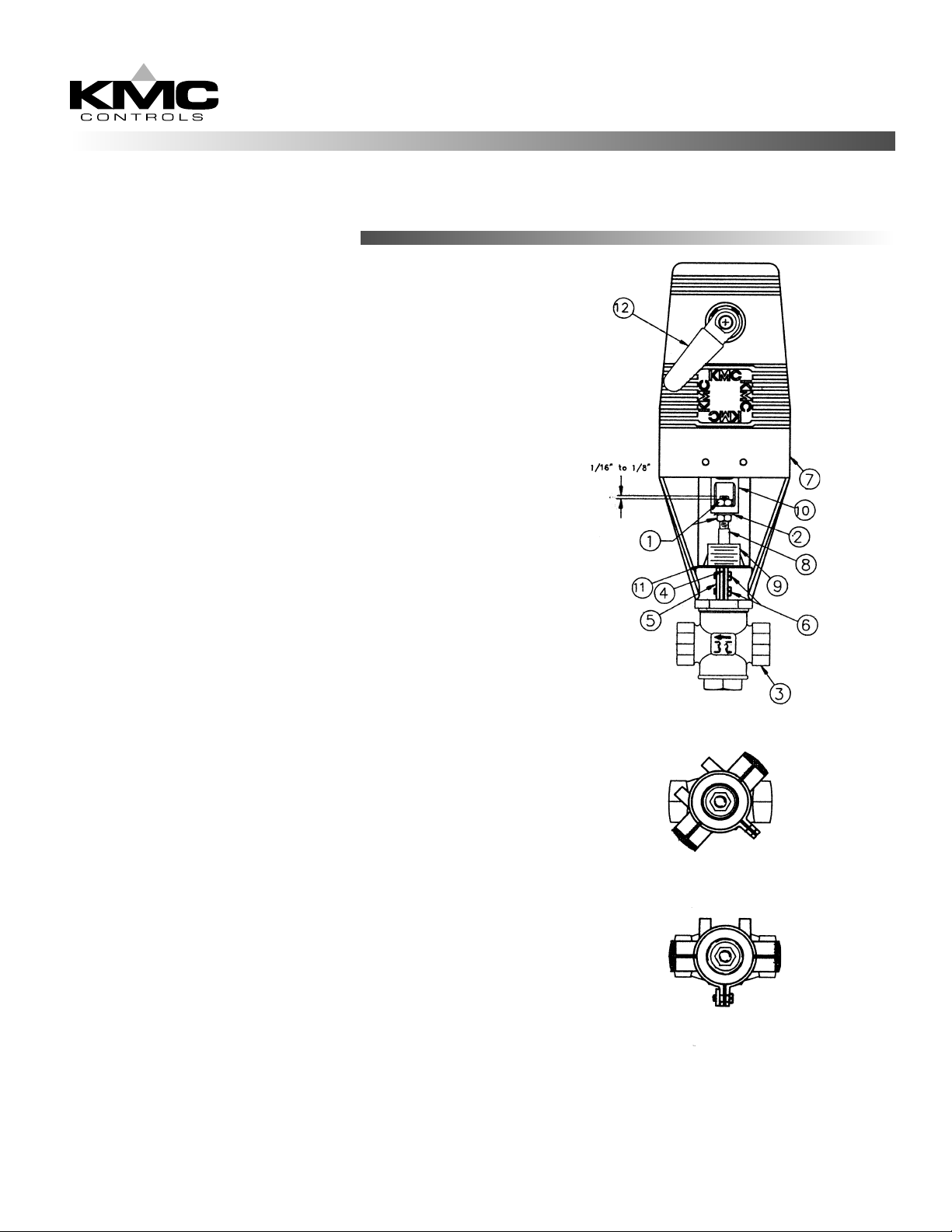
Mounting Linkage to Valve
1. Thread nut (1) onto valve stem (8) approximately 1".
2. Place flat washer (2) on top of nut (1).
3. Screw linkage (7) onto valve bonnet (9) until base of
linkage contacts the base of valve bonnet.
4. Rotate linkage to the position shown in FIG. 2.
NOTE: To properly position the linkage on the valve and
prevent the flange on the bonnet adaptor (11) from pulling
into the base of linkage, use a flat screwdriver to spread
the tabs apart slightly.
5. Gently tap the base of linkage housing, around the bonnet
adaptor (11), with a rubber mallet to properly seat the
housing against the adaptor.
6. Assemble washer plate (4) and threaded plate (5)
onto the housing tabs with 2 screws (6). Tighten the tab
screws (6) evenly until snug against the tabs.
7. Rotate the linkage to align it with the valve ports as shown
in FIG. 3.
8. Evenly torque the tab screws (6) to 25-30 in-lbs.
9. Face the lever (12) and rotate it counterclockwise until the
connecting rod (10) contacts the lower valve stem nut (1).
10. Thread the upper valve stem nut (1) onto the valve stem (8)
until 1/16" to 1/8" of valve stem is visible above the nut (1).
11. Rotate the lever (12) clockwise to lift the connecting rod
(10) up and around the upper valve stem nut flats (1).
12. Hold the connecting rod (10) with a wrench to keep it from
twisting and tighten the lower valve stem nut (1) against
the connecting rod.
13. Rotate the lever (12) until valve stem is in the full up
position.
14. Loosen the set screws on the lever (12). Reposition the
lever so that the end of the handle is just inside the left
side of the linkage housing. Tighten the 2 set screws on
lever.
Proceed to actuator mounting instructions.
HPO-5201 and 5202
FIG. 1
FIG. 2
FIG. 3
Page 2
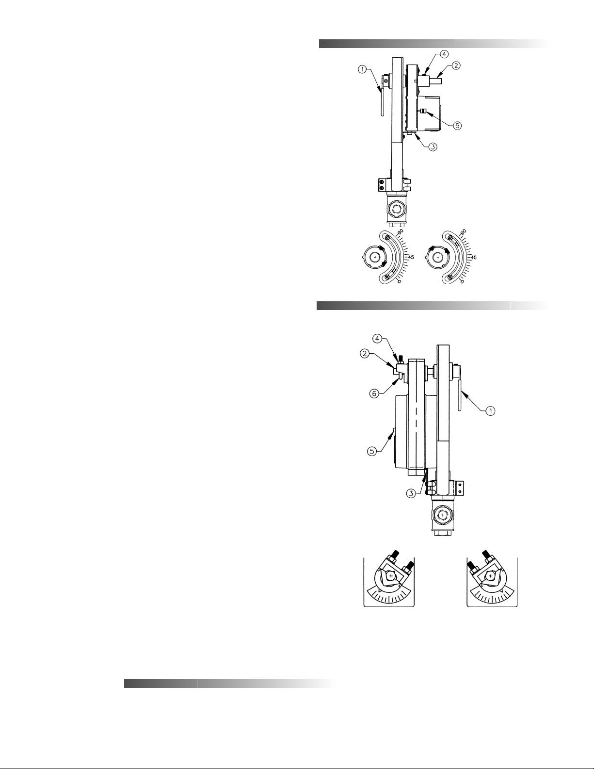
Mounting MEP-5000 Actuators to Linkage
1. Rotate the valve linkage lever (1) so that the valve stem is
fully down.
2. Depress the actuator’s disengagement button (5) and
manually position the edges of actuator pointer between
the 10° and 15° marks.
3. Place the actuator over the linkage shaft (2) and the nonrotation bracket (3).
4. Tighten 2 set screws (4) on the actuator output hub while
holding the linkage lever to ensure that the valve stem
stays down.
5. Confirm the unit’s operation by depressing the
disengagement button (5) and rotating the linkage lever (1)
in each direction.
NOTE: The pointer MUST NOT rotate past the 5° or 85°
marks (see FIG. 5 and FIG. 6).
6. If conditions in Step 5 are not met, loosen the 2 set screws
(4) and readjust.
Mounting MEP-1200 Actuators to Linkage
1. Rotate the valve linkage lever (1) so that valve stem is fully
down.
2. Depress the actuator’s disengagement button (5) and
manually position the pointer to the first mark from full
Clockwise (see FIG.8)
3. Place the actuator over the linkage shaft (2) and the nonrotation pin (3) until the cover on the actuator rests against
the linkage cover.
4. Finger tighten 2 coupler nuts (4) until the u-bolt (6) contacts
the linkage shaft (2).
5. Holding the linkage lever (1) to assure valve stem stays
down, and checking that the actuator cover is held against
the linkage, evenly torque the 2 coupler nuts (4) to 110-120
in-lbs.
6. Check final operation by depressing the disengagement
button (5) and rotating the linkage lever (1) in each
direction.
3-Way Valves: The valve seats should limit the actuator
pointer between the first mark from full clockwise (FIG. 8)
and the first mark from full counterclockwise (FIG. 9).
2-Way Valves: The valve seat should limit the actuator
pointer from passing the first mark from full clockwise
(FIG. 8).
7. Readjust, if needed, by loosening the 2 coupler nuts
(4) and adjusting.
Maintenance
No routine maintenance is required. Component are designed
for dependable, long term reliability and performance. Careful
installation will also ensure this performance.
FIG. 4
FIG. 5 FIG. 6
FIG. 8
KMC Controls
P.O. Box 497
19476 Industrial Drive
New Paris, IN 46553
TEL: 574.831.5250
www.kmccontrols.com
FIG. 7
FIG. 9
732-019-06B
 Loading...