

Page 1

FlexStat™ BACnet Programmable Thermostats
BAC-1xx63 Series (6 Relays, 3 Analog Outputs)
Installation Guide (6/3 Outputs)
MountingQuick Start
The KMC FlexStat series of intelligent temperature/
humidity-sensing, wall-mounted, thermostat/
controllers are native BACnet Advanced Application
Controllers (B-AAC) for use in a BACnet system.
The FlexStat simplies networked zone control for
common packaged HVAC equipment by including
an on-board library of programs that permits rapid
conguration of a wide range of HVAC control
applications.
To use the FlexStat:
1. Mount and wire the unit (see this Installation
Guide).
NOTE: This document gives basic mounting,
wiring, and setup information only. For
conguration, programming, operation,
and other information, see the KMC
Controls web site (www.kmccontrols.com)
for the latest documents and rmware. For
installation instructions of FlexStats with
output congurations other than 6 relays
and 3 analog outputs, see that model’s
respective installation guide.
2. Congure/program the unit (see the FlexStat
Operation and Application Guides).
3. If necessary, troubleshoot any issues (see the
FlexStat Operation Guide).
4. Operate the unit (see the FlexStat Operation
Guide).
1.125" (29)
Dimensions in inches (millimeters)
For optimum temperature sensor performance,
the FlexStat must be mounted on an interior wall
and away from heat sources, sunlight, windows,
air vents, and air circulation obstructions (e.g.,
curtains, furniture). (See the Application Guide for
more information.)
Additionally, for a model with an occupancy sensor option, be sure to install it where it will have
unobstructed view of the most typical trac area
(see the Application Guide for more information).
If replacing an existing thermostat, label wires as
needed for reference when removing the existing
thermostat.
1. Complete rough-in wiring at each location prior
to thermostat installation. Cable insulation must
meet local building codes.
2. Turn the hex screws in the boom and top of
the FlexStat clockwise until they clear the cover.
(See Illustration 1.) Pull the cover away from the
backplate (mounting base).
3. Route the wiring through the backplate.
4. With the embossed UP toward the ceiling, fasten
the backplate directly to a vertical 2 x 4 inch wall
handy-box. (For horizontal or 4 x 4 applications,
use the HMO-10000 wall mounting plate.)
5. Make the appropriate connections to the terminal
blocks. (See the Connections and Wiring section.)
6. Place the FlexStat cover over the backplate while
being careful not to pinch or dislodge any
wiring. Back the hex screws (counterclockwise)
out of the brackets until they engage the FlexStat
cover and hold it in place.
5.551"
(141)
4.192" (106)
EIA-485 data
port for quick
network access
Terminal blocks
on backplate for
easy wiring
Cover hex screws
CAUTION
To prevent mounting screw heads from touching the
circuit board in the thermostat, use only the mounting
screws supplied by KMC Controls. Using screws other
than the type supplied may damage the FlexStat.
NOTE: This document is for 6 relay and 3 analog
output BAC-1xx63 series only. See other in-
Illustration 1—Dimensions and Connections
BAC-1xx63 Series (6 Relays, 3 Analog Outputs) 1 Installation Guide
stallation guides for the proper FlexStat series.
Page 2
Connections and Wiring
Wiring Considerations
• Because of the many connections (power,
network, inputs, outputs, and their respective
grounds or switched commons), be sure wiring
is well planned before installation of conduit!
• To prevent excessive voltage drop, use a conduc-
tor size that is adequate for the wiring length!
Allow plenty of “cushion” to allow for transient peaks during startup.
• Make sure that conduit for all wiring has adequate diameter for all necessary wiring. Using
1-inch conduit and junction boxes is recommended! Use external junction boxes above the ceiling
or in another convenient location as needed
to make connections that run to the FlexStat’s
junction box.
• Using multiple conductor wires for all inputs
(e.g., six conductor) and outputs (e.g., 12 conductor) is recommended. Grounds for all the inputs
can be combined on one wire.
CAUTION
To avoid damage from ground loops and other
communication issues in networked FlexStats,
correct phasing on MS/TP network and power
connections on ALL the networked controllers is
critically important.
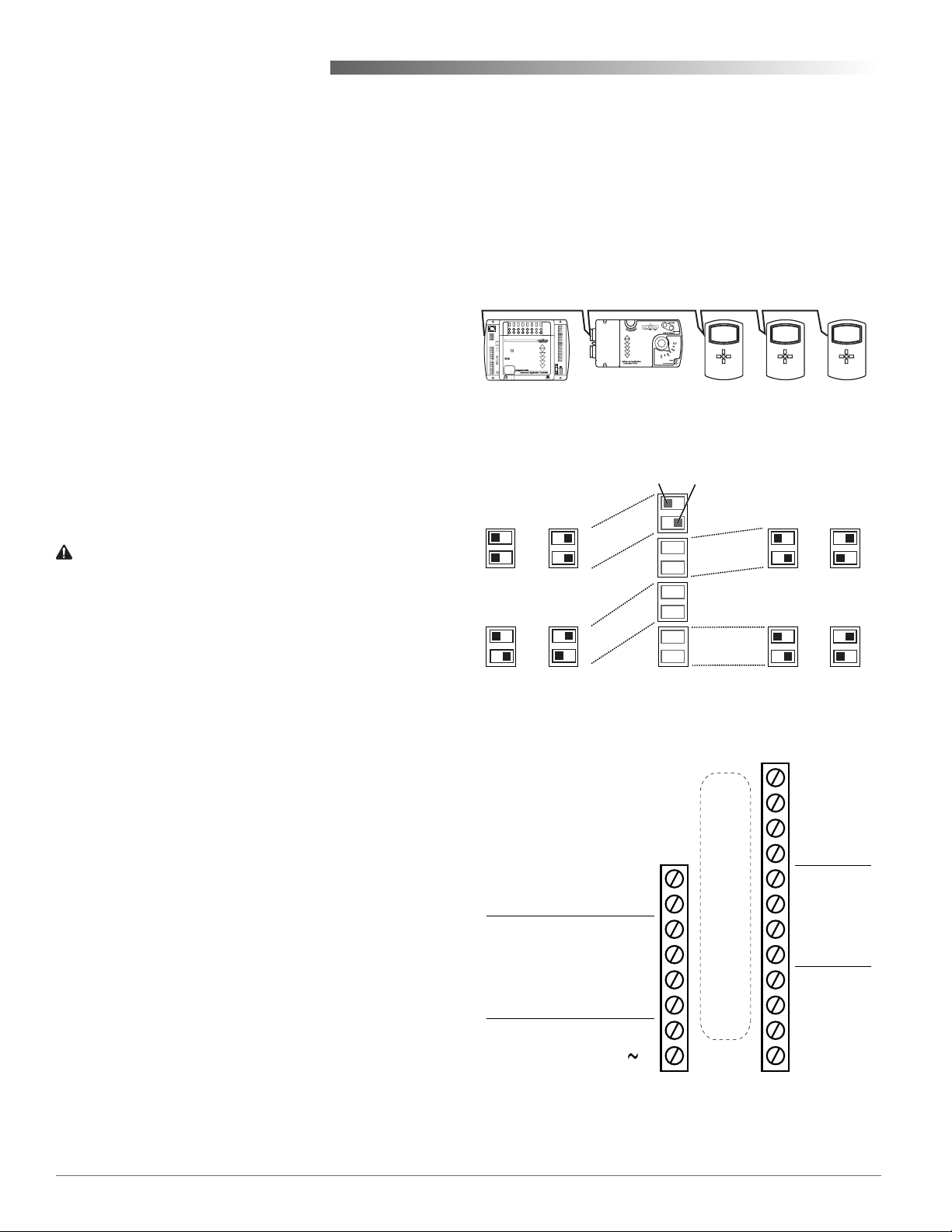
MS/TP EOL (End-Of-Line) Termination
The controllers/thermostats on the physical ends of
the EIA-485 wiring segment must have end-of-line
termination installed for proper network operation.
(See Illustrations 2 and 3.) If a FlexStat is at the physical end of the MS/TP network line, set both the EOL
termination switches (1 and 2) to On (to the right)
on the back of the circuit board. If not on the end,
ensure that both switches are O (le).
Illustration 2—MS/TP Network End-Of-Line Termination
Pushed Left Pushed Right
OFF
10K
EOL =
1
2
IN3 =
0-12 V
Ω
5
6
ON
1
2
1
2
5
6
3
4
5
6
7
8
10K Ω
Ω
10K
IN4 =
0-12 V
3
4
IN2 =
0-12 V
7
8
3
4
7
8
MS/TP Wiring
Connect the –A terminals in parallel with all other –A
terminals on the network and the +B terminals in paral-
lel with all other +B terminals. (See Illustrations 2 and
4.) Connect the shields of the cable (Belden cable #82760
or equivalent) together at each device. Use a wire nut or
the S terminal in KMC BACnet controllers. (FlexStats,
however, do not have an S terminal.) Connect the cable
shield to a good earth ground at one end only.
NOTE: The S terminal in KMC controllers is
provided as a connecting point for the
shield. The terminal is not connected to the
ground of the controller. When connecting
to controllers from other manufacturers,
verify the shield connection is not
connected to the controller’s ground.
For more information on principles and good practices when connecting an MS/TP network, see Planning
BACnet Networks (Application Note AN0404A).
Illustration 3—EOL and Pull-Up Switch Resistor Positions
NOTE: IN1 is the room temp.
sensor AI1
NOTE: SC = Switched
(Relay) Common
BACnet
MS/TP
Network
Inputs
(Wiring Inputs
and Outputs
Dependent on
Application)
Common/–/C
24 VAC
Illustration 4—(BAC-1xx63C) Terminals and Connections
Phase/ /R
+B
–A
IN4
IN3
GND
IN2
(Wiring Cutout in Backplate)
Outputs
Analog 9
GND 7–9
Analog 8
Analog 7
Relay 6
SC 4–6
Relay 5
Relay 4
Relay 3
SC 1–3
Relay 2
Relay 1
BAC-1xx63 Series (6 Relays, 3 Analog Outputs) 2 Installation Guide
Page 3

Input Connections
Output Connections
Passive input devices require pull-up resistors in
the circuit. For passive input devices (e.g., switch
contacts and Type III 10K ohm thermistors) on IN2
through IN4, set the pull-up switches on the back
of the circuit board to the 10K position. For active
voltage devices, set the switches to the 0–12 VDC
position. (See Illustrations 3 and 4.)
NOTE: Unlike the EOL switch pairs (1-2), the
INPUT switch pairs (3-4, 5-6, and 7-8)
must NOT have both switches set to the
le or both set to the right—if switch 3 is
set to the le, for example, switch 4 must
be set to the right (or vice versa). ALL the
input pull-up resistor switch pairs must
be fully latched in either 10K Ohm or
0–12 VDC positions even if a switch pair
has no input connected! A single incorrect
switch position may cause errors in multiple inputs.
NOTE: For more information on wiring specic
applications (AHU, FCU, HPU, RTU), see
the Applications section starting on page
4. (These applications are the packaged
programs selectable from the Advanced >
Application menu in the BAC-1xx63C models.) See also the FlexStat Application Guide
on www.kmccontrols.com.
NOTE: FlexStat inputs do not support 1K ohm
RTDs. To use a 4–20 current loop input or
map analog inputs as binary values, see the
FlexStat Application Guide.
Connect the device under control between the desired
output terminal and the related SC (Switched Com-
mon for relays) or GND (Ground for analog outputs)
terminal. (See Illustration 4). For the bank of three
relays, there is one Switched (relay) Common connection (in place of the GND terminal used with analog
outputs). (See Illustration 5).
One Switched
Common
Connection
Per Bank of
Three
Normally
Open Relays
Illustration 5—Switched (Relay) Common and Relays
Relay 3 (or 6)
SC 1–3 (or 4–6)
Relay 2 (or 5)
Relay 1 (or 4)
Do not aach a device that draws current exceeding
the FlexStat’s output capacity:
• Maximum output current for individual ANALOG outputs (7–9) is 20 mA @ 12 VDC (each).
• Max. output current is 1 A for individual
RELAYS @ 24 VAC/VDC or a total of 1.5 A per
bank of 3 relays (relays 1–3 and 4–6).
For example, KMC REE-3111/3112 relays could
be connected to the analog outputs, but REE-
3211/3221/3213 relays would exceed the FlexStat’s
analog output capacity (although the REE-3211 can
be used with the FlexStat’s internal relays 1–6 as
shown in the following applications pages).
FlexStat relays 1–6 are NO, SPST (Form “A”). (To
emulate binary outputs with the analog outputs, set
the output voltage to be either 0 or 12 VDC in Control
Basic.)
CAUTION
Relays are for Class-2 voltages (24 VAC) only. Do not
connect line voltage to the relays!
CAUTION
Do not mistakenly connect 24 VAC to an analog
output ground. This is not the same as a relay’s
switched common. See the backplate’s terminal
label for the correct terminal.
BAC-1xx63 Series (6 Relays, 3 Analog Outputs) 3 Installation Guide
Page 4

Power Connection
The FlexStat requires an external, 24 volt, AC power
source. Use a KMC Controls Class-2 transformer to
supply power. Connect the transformer’s neutral
lead to the 24 VAC Common/–/C terminal and the
AC phase lead to the 24 VAC Phase/
~/R terminal.
(See Illustration 4.) Power is applied to the FlexStat
when the transformer is plugged in.
KMC Controls recommends powering only one controller/thermostat from each transformer. If installing
a FlexStat in a system with other controllers/thermostats powered from a single transformer, however,
phasing must be correct and the total power drawn
from the transformer must not exceed its rating.
Accessories
HMO-10000 Horizontal or 4 x 4 handy box wall
mounting plate, light almond
HMO-10000W HMO-10000 in white
HPO-0044 Replacement cover hex screw
HTO-1103 FlexStat rmware ash upgrade
kit
KMD-5567 Network surge suppressor
KMD-5575 Network repeater/isolator
KMD-5576 EIA-485 to USB Communicator
KMD-5624 PC data port (EIA-485) cable
(FlexStat to USB Communicator)—included with the KMD5576 (buy for third-party EIA-232
interfaces)
SP-001 Flat blade and hex end screw-
driver (with KMC logo) for cover
hex screws
XEE-6111-040 Transformer, 120-to-24 VAC, 40
VA, single-hub
XEE-6112-040 Transformer, 120-to-24 VAC, 40
VA, dual-hub
Configuration
To congure the FlexStat, navigate the menus and
change seings by pressing a combination of buons.
Press the Right (Menu) buon and then the:
• Enter buon to select and/or exit value editing.
• Up/Down buon to move among entries (up/
down lines).
• Le/Right buon to move among value elds
(le/right spaces).
• Le buon to return to the Home screen.
Humidity and motion sensor options are dependent
on the FlexStat model. For operation, conguration,
troubleshooting, and other information, see the
FlexStat Operation Guide.
MAINMENU
ABOUT
ADVANCED
ALARM
DATE/TIME
SCHEDULE
SETPOINTS
SYSTEM
Illustration 6—Configuration Screens
NOTE: Applications on pages 5–9 are the packaged
programs selectable from the Advanced
> Application menu in the BAC-1xx63C
(only) models. Other FlexStat models have
other applications. Humidity and motion
sensor options are dependent on the
FlexStat model.
ADVANCED
APPLICATION
CBPROGRAMS
COMMUNICATION
DATE/TIME
DEVICE
INPUTS
LIMITS
(See
menus
on the
following
pages)
BAC-1xx63 Series (6 Relays, 3 Analog Outputs) 4 Installation Guide
Page 5

Applications
Air Handler Unit (AHU)—
Modulating Heat and Modulating Cool
NOTE: See also the RTU section
for 2-stage options.
REE-3211 Multi-Voltage Relay
XEE-6311-075/6311-100 Transformer
MEP-5372/7252/7552/7852 Fail-Safe Actuators
XEE-6311-075 Transformer
VEP-45xxB895/VEB-43xxxBDL Valves with MEP-5372 Fail-Safe Actuators
AHU LAYOUT
APPLICATION
DEGREESSCALE:°F
APP:
AIRHANDLER
ADDITIONALSETUP
ADDITIONALSETUP
DAMPER
FAN
HUMIDITY
SENSORS
VALVE
Input Terminals AHU Input Connections BACnet Objects
IN4 Opt. Outside Air Temp. (OAT)* AI4
IN3 Opt. Mixed Air Temp. (MAT)* AI3
GND Ground
IN2 Optional FST or DAT** AI2
*When using optional Outside Air Damper, must also have MAT/OAT
inputs (typically 10K, Type III thermistors). Ensure pull-up resistor
switch positions are set properly—see Illustration 3 on page 2.
**Fan Status (FST) or Discharge Air Temperature (DAT) is an optional,
selectable input. Ensure pull-up resistor switch positions are set
properly (10K position) for the relay, switch, or Type III thermistor.
CSE-1102 Air Differential
Pressure Switch
STE-1402 Duct
Sensor, Type III
NOTE: EITHER FAN STATUS (FST) OR
DISCHARGE AIR TEMP (DAT) CAN
BE USED ON IN2, BUT NOT BOTH.
STE-1416 Duct Averaging Temp. Sensor
STE-1451 Outside Air Temp. Sensor
Output
Terminals
Analog 9 Outside Air Damper (OAD/RTD)* AO9
GND Ground (for analog output terminals 7–9)
Analog 8 Heating Valve (HTV) AO8
Analog 7 Cooling Valve (CLV) AO7
Relay 6 (BO6)
SC 4–6
Relay 5 (BO5)
Relay 4 (BO4)
Relay 3 (BO3)
SC 1–3 24 VAC (for relay terminals 1–3)
Relay 2 (BO2)
Relay 1 Fan BO1
*If optional Outside Air Damper is used, must also have MAT/OAT inputs.
AHU Output Connections
(Modulating)
BACnet
Objects
NOTE: Connections and menus reect rmware
version R1.3.0.4 or later.
BAC-1xx63 Series (6 Relays, 3 Analog Outputs) 5 Installation Guide
Page 6

Heat Pump Unit (HPU)—
1 or 2 Compressors with Auxiliary and Emergency Heat
CAUTION
Relays are for Class-2 voltages (24 VAC) only.
Do not connect line voltage to the relays!
Do not mistakenly connect 24 VAC to an
analog output ground.
XEE-6311-075 or XEE-6311-100 Transformer
HPU LAYOUT
MEP-5372/7252/7552/7852 Fail-Safe Actuators
CSE-1102 Air Differential
Pressure Switch
STE-1402 Duct
Sensor, Type III
NOTE: EITHER FAN STATUS (FST) OR
DISCHARGE AIR TEMP (DAT) CAN
BE USED ON IN2, BUT NOT BOTH.
STE-1416 Duct Averaging Temp. Sensor
STE-1451 Outside Air Temp. Sensor
NOTE: WIRE TO “O” TERMINAL IF
REVERSING VALVE IS
ENERGIZED IN COOLING
MODE; WIRE TO “B”
TERMINAL IF REVERSING
VALVE IS ENERGIZED IN
HEATING MODE.
NOTE: Although
typical
terminal
code leers
are shown,
check the
schematics
of your unit
for wiring
details.
APPLICATION
DEGREESSCALE:°F
APP:
HEATPUMP
OPT:1STAGE
ADDITIONALSETUP
ADDITIONALSETUP
AUXHEAT
DAMPER
FAN
HUMIDITY
SENSORS
VALVE
NOTE: To see Humidity options in the Additional
Setup menu, select an Aux. Heat option
other than None (the default).
Input Terminals HPU Input Connections BACnet Objects
IN4 Opt. Outside Air Temp. (OAT)* AI4
IN3 Opt. Mixed Air Temp. (MAT)* AI3
GND Ground
IN2 Optional FST or DAT** AI2
*When using optional Outside Air Damper, must also have MAT/OAT
inputs (typically 10K, Type III thermistors). Ensure pull-up resistor
switch positions are set properly—see Illustration 3 on page 2.
**Fan Status (FST) or Discharge Air Temperature (DAT) is an optional,
selectable input. Ensure pull-up resistor switch positions are set
properly (10K position) for the relay, switch, or Type III thermistor.
Output
Terminals
Analog 9 Outside Air Damper (OAD/RTD)* AO9
GND
Analog 8 (AO8)
Analog 7 (AO7)
Relay 6 W2/E Emergency Heat (Optional) BO6
SC 4–6 R 24 VAC (for relay terminals 4–6)
Relay 5 W Auxiliary Heat (Optional) BO5
Relay 4 Y2 Compressor 2 (Optional) BO4
Relay 3 Y1 Compressor 1 BO3
SC 1–3 R 24 VAC (for relay terminals 1–3)
Relay 2 O/B
Relay 1 G Fan BO1
*If optional Outside Air Damper is used, must also have MAT/OAT inputs.
Typical
Terminal
Codes
HPU Output Connections
Ground
(for analog output terminals 7–9)
Reversing Valve
(see O/B Note in schematic)
BACnet
Objects
BO2
BAC-1xx63 Series (6 Relays, 3 Analog Outputs) 6 Installation Guide
Page 7

Roof Top Unit (RTU)— 1 or 2 Heat and 1 or 2 Cool
NOTE: Terminal connections and menus
reect rmware version R1.3.0.4 or
later. (Relay 3 and 4 were swapped in
versions earlier than R0.0.0.0.)
XEE-6311-075 or XEE-6311-100 Transformer
RTU 2H/2C LAYOUT
MEP-5372/7252/7552/7852 Fail-Safe Actuators
CSE-1102 Air Differential
Pressure Switch
NOTE: EITHER FAN STATUS (FST) OR
DISCHARGE AIR TEMP (DAT) CAN
BE USED ON IN2, BUT NOT BOTH.
STE-1416 Duct Averaging Temp. Sensor
STE-1451 Outside Air Temp. Sensor
RC AND RH TERMINALS ARE PRESENT:
IF BOTH
WIRE RC TO SC 1-3 AND RH TO SC 4-6.
IF ONLY ONE “R” TERMINAL IS PRESENT:
WIRE BOTH SC 1-3 AND SC 4-6 TO R.
STE-1402 Duct
Sensor, Type III
NOTE: This was 2 Heat and 2 Cool in
rmware R1.3.04 and earlier.
Multistage was added later.
APPLICATION
DEGREESSCALE:°F
APP:
ROOFTOP
OPT:1H/1C
ADDITIONALSETUP
ADDITIONALSETUP
DAMPER
FAN
HUMIDITY
SENSORS
NOTE: Although typical terminal code leers are
shown, check the schematics of your unit for
wiring details.
Input Terminals RTU Input Connections BACnet Objects
IN4 Opt. Outside Air Temp. (OAT)* AI4
IN3 Opt. Mixed Air Temp. (MAT)* AI3
GND Ground
IN2 Optional FST or DAT** AI2
*When using optional Outside Air Damper, must also have MAT/OAT
inputs (typically 10K, Type III thermistors). Ensure pull-up resistor
switch positions are set properly—see Illustration 3 on page 2.
**Fan Status (FST) or Discharge Air Temperature (DAT) is an optional,
selectable input. Ensure pull-up resistor switch positions are set
properly (10K position) for the relay, switch, or Type III thermistor.
Output
Terminals
Analog 9 Outside Air Damper (OAD/RTD)* AO9
GND
Analog 8 (AO8)
Analog 7 (AO7)
Relay 6 (BO6)
SC 4–6 RH/R 24 VAC (for relay terminals 4–6)
Relay 5 W2 Heat 2 (Optional) BO5
Relay 4 W1 Heat 1 BO4
Relay 3 Y2 Cool 2 (Optional) BO3
SC 1–3 RC/R 24 VAC (for relay terminals 1–3)
Relay 2 Y1 Cool 1 BO2
Relay 1 G Fan BO1
*If optional Outside Air Damper is used, must also have MAT/OAT inputs.
Typical Terminal
Codes
RTU Output Connections
(1 or 2 H and 1 or 2 C)
Ground
(for analog output terminals 7–9)
BACnet
Objects
BAC-1xx63 Series (6 Relays, 3 Analog Outputs) 7 Installation Guide
Page 8

Fan Coil Unit (FCU)—
2 or 4 Pipe, Modulating or 2 Position
FCU 4-PIPE
MODULATING LAYOUT
(See the FCU—Other Options section on the next page for more options)
CSE-1102 Air Differential
Pressure Switch
4-PIPE MODULATING OPTION
XEE-6311-050 Transformer
VEP-45xxB745/
VEB-43xxxBCK
MEP-4002 0–10
VDC Actuators
NOTE: EITHER FAN STATUS (FST) OR
DISCHARGE AIR TEMP (DAT) CAN
BE USED ON IN2, BUT NOT BOTH.
Valves with
STE-1402 Duct
Sensor, Type III
NOTE:
Humidity
and occupancy sensor
options are
dependent
on FlexStat
model.
Input Terminals FCU Input Connections BACnet Objects
IN4 (AI4)
IN3 Supply Water Temp. (W-TMP)* AI3
GND Ground
IN2 Optional FST or DAT** AI2
*Input for Supply Water Temp is typically a 10K,Type III thermistor.
Ensure pull-up resistor switch positions are set properly—see
Illustration 3 on page 2.
**Fan Status (FST) or Discharge Air Temperature (DAT) is an optional,
selectable input. Ensure pull-up resistor switch positions are set
properly (10K position) for the relay, switch, or Type III thermistor.
APPLICATION
DEGREESSCALE:°F
APP:
FANCOIL
OPT:4–PIPE
ADDITIONALSETUP
ADDITIONALSETUP
FAN
HUMIDITY
SENSORS
VALVE
NOTE: To see Humidity options in
the Additional Setup menu,
select the 4-Pipe option.
REE-3211 Multi-Voltage Relays
Output Terminals
(BAC-1xxx63C)
Analog 9 (AO9)
GND
Analog 8
Analog 7
Relay 6 (BO6)
SC 4–6 24 VAC (for relay terminals 4–6)
Relay 5
NOTE:
Do not use
REE-3211s
with analog
outputs!
See Output
Connections
on page 3.
BAC-1xx63 Series (6 Relays, 3 Analog Outputs) 8 Installation Guide
Relay 4
Relay 3 Fan 3 BO3
SC 1–3 24 VAC (for relay terminals 1–3)
Relay 2 Fan 2 BO2
Relay 1 Fan 1 BO1
*If optional Outside Air Damper is used, must also have MAT/OAT inputs.
FCU Output Connections
2-Pipe 4-Pipe
(for analog output terminals 7–9)
Valve,
Proportional (VLV)
Valve,
2-Position (VLV)
Ground
Heat Valve,
Proportional (HTV)
Cool Valve,
Proportional (CLV)
Heat Valve,
2-Position (HTV)
Cool Valve,
2-Position (CLV)
BACnet
Objects
AO8
AO7
BO5
BO4
Page 9

Fan Coil Unit (FCU)—Other Options
Additional Resources
NOTE: See the FCU—Overview section on the
previous page for the 4-Pipe Modulating
option and the general schematic.
(4-PIPE 2-POSITION FCU OPTION)
XEE-6311-050 Transformer
BL U (V EP Series) or BLK (VEZ Series
BR N (V EP Series) or RED (VEZ Series
VEP-1xxx0186/VEZ-4xxxxMBx
Valves with 24 VAC Actuators
(See Wire
Colors
Above
)
N.O.
)
)
N.C.
The latest support les are always available on the
KMC Controls web site (www.kmccontrols.com). To
see all available les, you will need to log-in to the
Partners site.
For specications, see the FlexStat Data Sheet.
For operation, conguration, troubleshooting,
and other information, see the FlexStat Operation
Guide.
For additional wiring, application, and programming information, see the FlexStat Application
Guide.
For additional instructions on programming, see the
Help system for BACstage or TotalControl.
(2-PIPE MODULATING FCU OPTION)
XEE-6311-050 Transformer
VEP-45xxB745/
VEB-43xxxBCK
MEP-4002 0–10
STE-1454 Temp. Sensor
(2-PIPE 2-POSITION FCU OPTION)
XEE-6311-050 Transformer
VEP-1xxx0186/VEZ-4xxxxMBx
Valve with 24 VAC Actuator
BL U (V EP Series) or BLK (VEZ Series
BR N (V EP Series) or RED (VEZ Series
STE-1454
Temp. Sensor
)
)
Valve with
VDC Actuator
Important Notices
The material in this document is for information
purposes only. The contents and the product it
describes are subject to change without notice.
KMC Controls, Inc. makes no representations or
warranties with respect to this document. In no event
shall KMC Controls, Inc. be liable for any damages,
direct or incidental, arising out of or related to the
use of this document.
KMC Controls, Inc.
19476 Industrial Drive
PO Box 497
New Paris, IN 46553
574.831.5250; Fax 574.831.5252
www.kmccontrols.com; info@kmccontrols.com
BAC-1xx63 Series (6 Relays, 3 Analog Outputs) 9 Installation Guide
© 2010 KMC Controls, Inc. 913-019-01I
 Loading...