

KMC Controls FlexStat BAC-12xx36 Series, FlexStat BAC-13xx36 Series, FlexStat BAC-14xx36 Series Installation Manual
Page 1

BAC-12xx36/13xx36/14xx36 Series FlexStat
3 Relays, 6 Analog Outputs, 6 External Inputs
Installation Guide (3/6 Outputs)
MountingQuick Start
™
CAUTION
This document is for 3-relay, 6-analog-output,
6-external-input BAC-12xx36/13xx36/14xx36 series
only. THESE MODELS ARE NOT COMPATIBLE
WITH THE BACKPLATES OF OLDER BAC-10000
SERIES FLEXSTATS (WITH ONLY 3 EXTERNAL
INPUTS)! If replacing an older 3-input FlexStat,
replace the backplate as well. See other installation
guides for other models.
To select and use a FlexStat in an application:
1. Select the appropriate model for the intended
application and options (see the FlexStat Data
Sheet).
2. Mount and wire the unit (see this Installation
Guide).
3. Congure/program the unit (see the FlexStat
Operation and Application Guides).
4. If necessary, troubleshoot any issues (see the
FlexStat Operation Guide).
5. Operate the unit (see the FlexStat Operation
Guide).
NOTE: This document gives basic mounting,
wiring, and setup information only. For
conguration, programming, operation,
and other information, see the KMC
Controls web site for the latest documents.
Models
BAC-12xxxx (shown) 1.125 (29)
BAC-13xxxx/14xxxx 1.437 (36.5) 5.192 (132)
A
Dimensions in Inches (mm)
A B C
4.192 (106)
5.551
(141)
Embossed “UP” indicator
For optimum temperature sensor performance,
the FlexStat must be mounted on an interior wall
and away from heat sources, sunlight, windows,
air vents, and air circulation obstructions (e.g.,
curtains, furniture). Additionally, for a model with
an occupancy sensor option, install it where it will
have unobstructed view of the most typical trac
area. (See the FlexStat Application Guide for more
information.)
If replacing an existing thermostat, label wires as
needed for reference when removing the existing
thermostat.
1. Complete rough-in wiring at each location prior
to thermostat installation. Cable insulation must
meet local building codes.
CAUTION
To prevent mounting screw heads from touching the
circuit board in the thermostat, use only the mounting
screws supplied by KMC Controls. Using other screws
may damage the FlexStat. Do not turn screws in
farther than necessary to remove the cover.
2. If the cover is locked on the backplate, turn the
hex screws in the boom and top of the FlexStat
CLOCKWISE until they (just) clear the cover.
(See Illustration 1.) Pull the cover away from the
backplate (mounting base).
3. Route the wiring through the backplate.
4. With the embossed “UP” and arrows toward the
ceiling, fasten the backplate to a wall handy-box.
BAC-12xxxx models mount directly on vertical 2
x 4 inch boxes, but they require an HMO-10000/
HMO-10000W wall mounting plate for horizontal
or 4 x 4 boxes. BAC-13xxxx/14xxxx models mount
directly on any of those types of boxes.
EIA-485 data
B
port (for quick
network access)
5. Make the appropriate connections to the terminal
blocks. (See Connections and Wiring on page 2.)
6. Place the FlexStat cover over the backplate while
Terminal blocks on
backplate (rotated on
BAC-13xxxx/14xxxx)
C
Illustration 1—Dimensions and Installation
BAC-12xx36/13xx36/14xx36 Series FlexStat 1 Installation Guide, Rev. E
Cover locking hex screws
being careful not to pinch or dislodge any
wiring. Back the hex screws (counterclockwise)
out of the brackets until they engage the FlexStat
cover and hold it in place.
Page 2
Connections and Wiring
Wiring Considerations
• Because of the many connections (power,
network, inputs, outputs, and their respective
grounds or switched commons), be sure wiring
is well planned before installation of conduit!
• Make sure that conduit for all wiring has adequate diameter for all necessary wiring. Using
1-inch conduit and junction boxes is recommended! Use external junction boxes above the ceiling
or in another convenient location as needed
to make connections that run to the FlexStat’s
junction box.
• To prevent excessive voltage drop, use a conduc-
tor size that is adequate for the wiring length!
Allow plenty of “cushion” to allow for tran-
sient peaks during startup.
• Using multiple conductor wires for all inputs
(e.g., 8 conductor) and outputs (e.g., 12 conductor) is recommended. Grounds for all the inputs
can be combined on one wire.
CAUTION
To avoid damage from ground loops and other
communication issues in networked FlexStats,
correct phasing on MS/TP network and power
connections on ALL the networked controllers is
critically important.
Network Wiring
For Ethernet or IP communications, plug an Ethernet
cable into the RJ-45 jack on the back of the FlexStat.
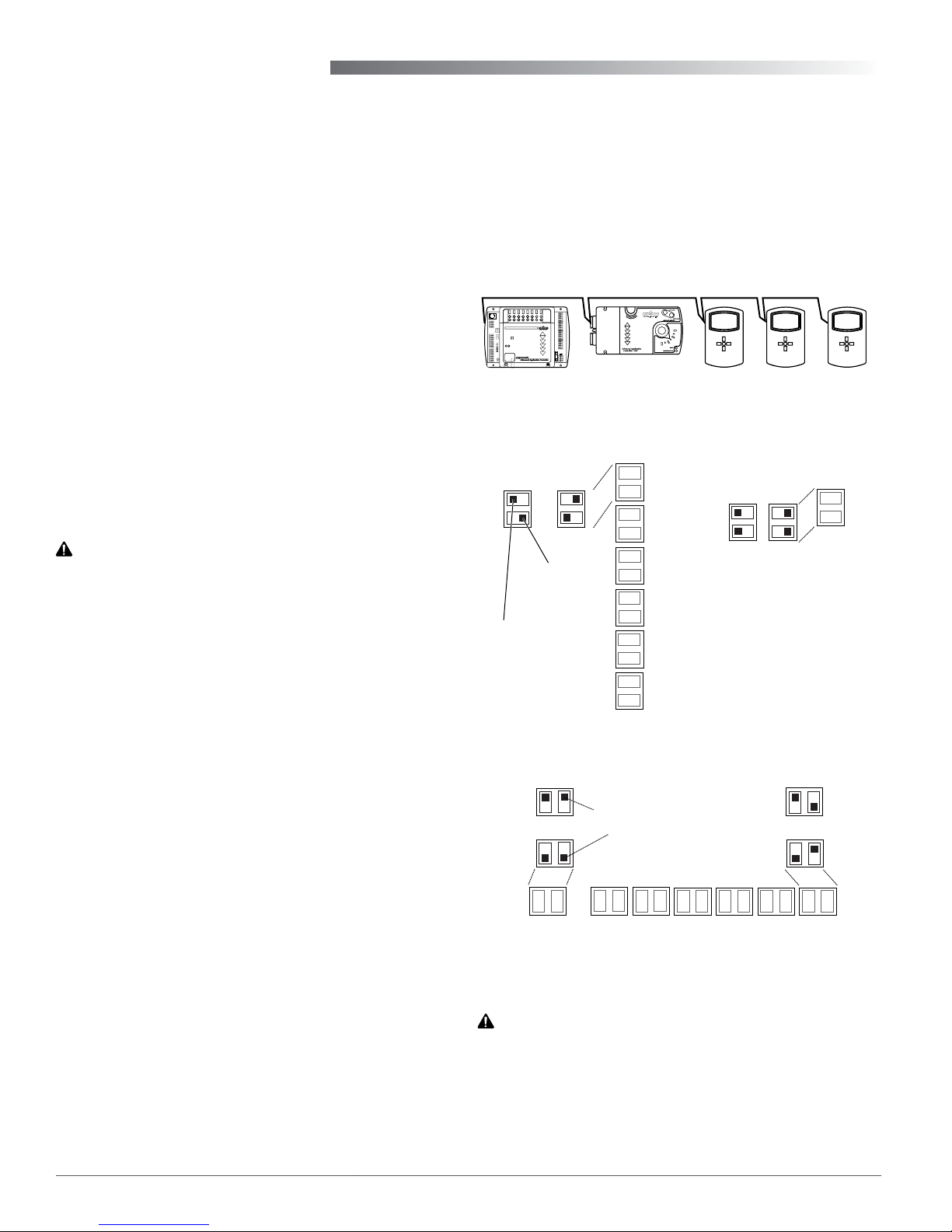
MS/TP EOL (End-Of-Line) Termination
The controllers/thermostats on the physical ends of
an EIA-485 wiring segment must have end-of-line
termination installed for proper network operation.
(See Illustrations 2 through 4.) If a FlexStat is at the
physical end of the MS/TP network line, set both the
EOL termination switches to On (to the right/up)
on the back of the circuit board. If not on the end,
ensure that both switches are O (left/down).
Illustration 2—MS/TP Network End-Of-Line Termination
Input Pull-Up Switches
EOL Switches
OFF
ON
NOTE: EOL = End
Of Line of BACnet
MS/TP network.
NOTE: 10K Ω inputs
are configurable for
Type II or Type III
thermistors in
FlexStat’s menu.
Left
0-12 V
Switch
Pushed
Right
IN9
IN8
IN7
IN4
IN3
IN2
10K Ω
Switch
Pushed
Illustration 3—BAC-12xxxx EOL/Pull-Up Switch Positions
For MS/TP communications, connect the –A terminals in parallel with all other –A terminals on the
network and the +B terminals in parallel with all
other +B terminals. (See Illustrations 2 and 5.) Connect the shields of the cable (Belden cable #82760 or
equivalent) together at each device. Use a wire nut or
the S terminal in KMC BACnet controllers. (FlexStats,
however, do not have an S terminal.) Connect the
cable shield to a good earth ground at one end only.
NOTE: The S terminal in KMC controllers is
provided as a connecting point for the
shield. The terminal is not connected to the
ground of the controller. When connecting
to controllers from other manufacturers,
verify the shield connection is not
connected to the controller’s ground.
For more information on principles and good practices when connecting an MS/TP network, see Planning
BACnet Networks (Application Note AN0404A).
BAC-12xx36/13xx36/14xx36 Series FlexStat 2 Installation Guide, Rev. E
ON
Switch Pushed Up
OFF
EOL
Switches
Illustration 4—BAC-13xxxx/14xxxx Switch Positions
Pushed Down
IN2 IN3 IN4 IN7 IN8
Input Pull-Up Switches
0-12 VDC
10K Ohm
IN9
CAUTION
This document is for 3-relay, 6-analog-output,
6-external-input BAC-12xx36/13xx36/14xx36 series
ONLY. THESE MODELS ARE NOT COMPATIBLE WITH
THE BACKPLATES OF OLDER BAC-10000 SERIES
FLEXSTATS (WITH ONLY 3 EXTERNAL INPUTS)!
If replacing an older 3-input FlexStat, replace the
backplate as well.
Page 3
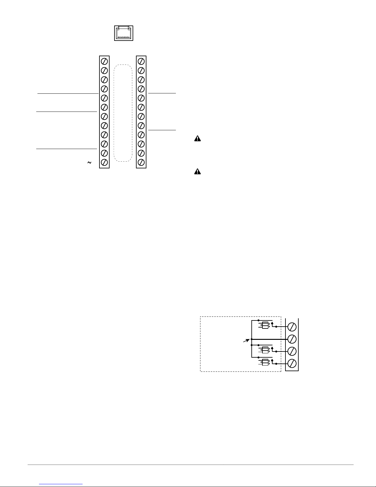
NOTE: SC = Switched
(relay) Common
NOTE: IN1 and IN5–6 are
reserved for internal sensors
Inputs
(Wiring is
dependent on
application)
MS/TP
Network
Inputs
24 VAC
Illustration 5—(BAC-12xx36) Terminals and Connections
Common/–/C
Phase/ /R
IN9
IN8
GND
IN7
+B
–A
IN4
IN3
GND
IN2
(Wiring Cutout in Backplate)
IP/Ethernet
Network
(Optional)
Outputs
Analog 9
GND 7–9
Analog 8
Analog 7
Analog 6
GND 4–6
Analog 5
Analog 4
Relay 3
SC 1–3
Relay 2
Relay 1
NOTE: On BAC-13xxxx/14xxxx models, terminals
are rotated 90° CCW.
Input Connections
Passive input devices require pull-up resistors in the
circuit. For passive input devices (e.g., switch contacts and 10K ohm thermistors) on IN2 through IN4
and IN7 through IN9, set the pull-up switches on
the back of the circuit board to the 10K position. For
active voltage devices, set the switches to the 0–12
VDC position. (See Illustrations 3 through 5.)
NOTE: Unlike the EOL switch pairs, the INPUT
switch pairs must NOT have both switch-
es set to the same direction—if one of the
pair’s switches is set to the left, for example,
the other must be set to the right (or vice
versa). ALL the input pull-up resistor
switch pairs must be fully latched in either 10K Ohm or 0–12 VDC position even
if a switch pair has no input connected! A
single incorrect switch position may cause
errors in multiple inputs.
NOTE: To use a 4–20 current loop input or map
analog inputs as binary values, see the
FlexStat Application Guide.
NOTE: To use a remote SAE-10xx CO
sensor, see
2
the FlexStat Operation Guide.
NOTE: For more information on wiring specic
applications (AHU and FCU), see Appli-
cations on page 5. (These applications
are the packaged programs selectable from
the Advanced > Application menu in the
BAC-1xxx36 models.) See also the FlexStat
Application Guide.
CAUTION
Relays are for Class-2 voltages (24 VAC) only. Do not
connect line voltage to the relays!
CAUTION
Do not mistakenly connect 24 VAC to an analog
output ground. This is not the same as a relay’s
switched common. See the backplate’s terminal
label for the correct terminal.
Output Connections
Connect the device under control between the desired
output terminal and the related SC (Switched Com-
mon for relays) or GND (Ground for analog outputs)
terminal. (See Illustration 5). For the bank of three
relays, there is one Switched (relay) Common connection (in place of the GND terminal used with analog
outputs). (See Illustration 6.) For the relay circuit, the
phase side of the AC should be connected to the SC
terminal.
One Switched
Common
Connection in
Bank of Three
Normally
Open Relays
Relay 3
SC (Phase) 1–3
Relay 2
Relay 1
NOTE: Type II or III 10K ohm thermistors can be
selected by changing the menu seing in
Advanced > Inputs > Input # > Sensor (see
Conguration on page 4). If a remote
space temperature sensor is connected to
AI7, space temperature can be congured
for onboard, remote, averaging of the two,
the lowest reading, or the highest reading.
NOTE: FlexStat inputs do not support 1K ohm
RTDs.
BAC-12xx36/13xx36/14xx36 Series FlexStat 3 Installation Guide, Rev. E
Illustration 6—Switched (Relay) Common and Relays
Do not aach a device that draws current exceeding
the FlexStat’s output capacity:
• Maximum output current for individual ANALOG outputs (4–9) is 20 mA @ 12 VDC (each).
• Max. output current is 1 A for individual RELAYS
@ 24 VAC/VDC or a total of 1.5 A for relays 1–3.
Page 4
For example, (discontinued) KMC REE-3211 relays
would exceed the FlexStat’s analog output capacity,
but they can be used with the FlexStat’s internal
relays 1–3 as shown in the following applications
pages. (Use a Core Components CVR11C-0/LD96200
in the REE-3211’s place in those applications.)
FlexStat relays 1–3 are NO, SPST (Form “A”). (To
emulate binary outputs with the analog outputs, set
the output voltage to be either 0 or 12 VDC in Control
Basic.)
NOTE: Applications on pages 5–11 are the
packaged programs selectable from the
Advanced > Application menu in the
BAC-1xxx36 (only) models. Other FlexStat
models have other applications.
NOTE: Humidity, motion, and CO
sensor options
2
in menus are dependent on the FlexStat
model and selected application.
For detailed conguration, operation, troubleshoot-
ing, and other information, see the FlexStat Opera-
tion Guide.
Power Connection
The FlexStat requires an external, 24 volt, AC power
source. Use a KMC Controls Class-2 transformer to
supply power. Connect the transformer’s neutral
lead to the 24 VAC Common/–/C terminal and the
AC phase lead to the 24 VAC Phase/~/R terminal.
(See Illustration 5.) Power is applied to the FlexStat
when the transformer is powered.
KMC Controls recommends powering only one controller/thermostat from each transformer. If installing
a FlexStat in a system with other controllers/thermostats powered from a single transformer, however,
phasing must be correct and the total power drawn
from the transformer must not exceed its rating.
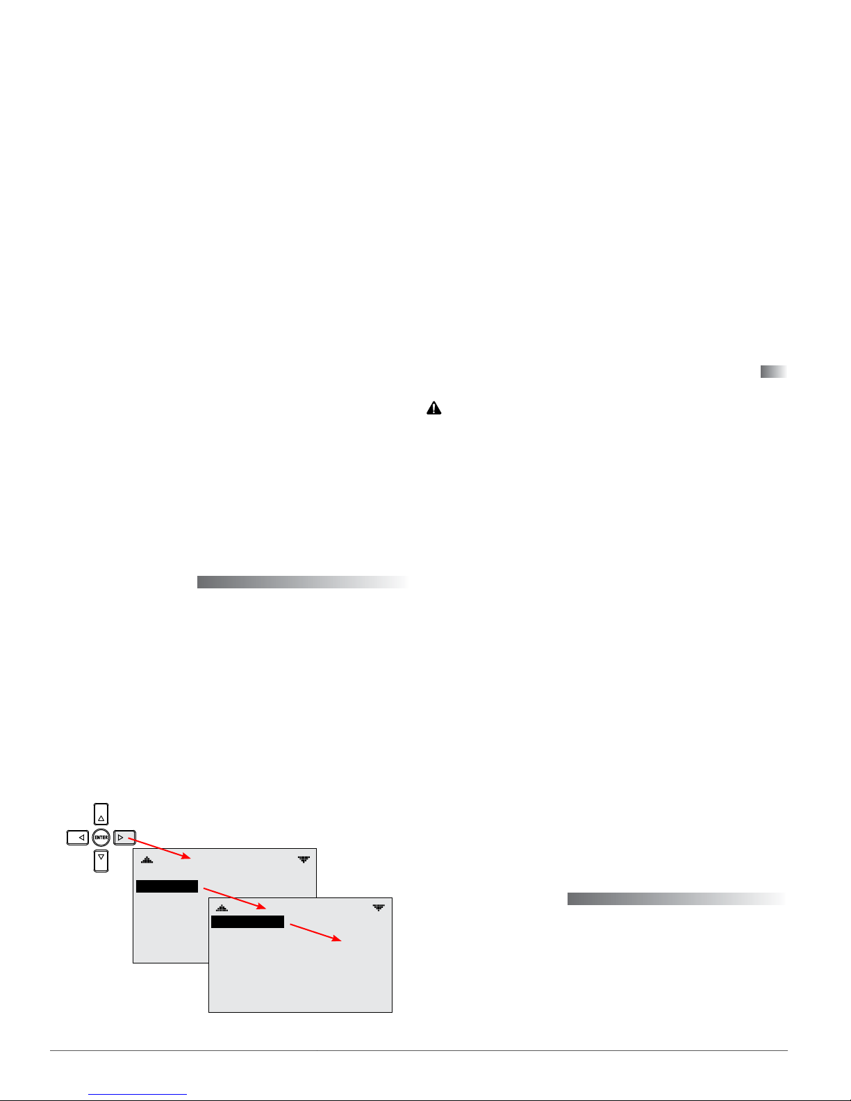
Configuration
To congure the FlexStat, navigate the menus and
change seings by pressing a combination of buons.
Press the Right (Menu) buon and then the:
• Enter buon to select and/or exit value editing.
• Up/Down buon to move among entries (up/
down lines).
• Left/Right buon to move among value elds
(left/right spaces).
• Left buon to return to the Home screen.
MAIN MENU
ABOUT
ADVANCED
ALARM
DATE/TIME
SCHEDULE
SETPOINTS
SYSTEM
Illustration 7—Configuration Screens
ADVANCED
APPLICATION
CB PROGRAMS
COMMUNICATION
DATE/TIME
DEVICE
INPUTS
LIMITS
(See
menus
on the
following
pages)
For additional wiring, customization, programming, and application information, see the FlexStat
Application Guide.
Applications Notes and Cautions
CAUTION
Relays are for Class-2 voltages (24 VAC) only. Do not
connect line voltage to the relays!
Do not mistakenly connect 24 VAC to an analog
output ground.
NOTE: Although typical terminal code leers are
shown, check the schematics of your unit
for wiring details!
NOTE: These applications are for 3 relay and 6 ana-
log output BAC-12xx36/13xx36/14xx36 series
only. See other installation guides for other
models.
NOTE: CO2, humidity, and motion sensor options
are dependent on FlexStat model.
NOTE: For Bill of Materials listings of the various
accessories shown in the sample diagrams,
see the FlexStat Application Guide.
NOTE: Since the KMC REE-3211 is discontin-
ued, use Core Components CVR11C-0/
LD96200 in its place. Do not use either
with analog outputs! See Output Connec-
tions on page 3.
Maintenance
Remove dust as necessary from the holes in the top
and boom. Clean the display with a soft, damp
cloth and mild soap.
To maintain maximum sensitivity of the built-in
motion sensor, occasionally wipe dust or dirt o the
lens—but do not use any uid on the sensor.
BAC-12xx36/13xx36/14xx36 Series FlexStat 4 Installation Guide, Rev. E
Page 5

Applications
FCU (Fan Coil Unit)—2 Pipe, Modulating
APPLICATION
DEGREES SCALE: °F
APP:
FAN COIL
OPT: 2–PIPE
ADDITIONAL SETUP
VEB-43 Valve with MEP-4002V Actuator
NOTE: In rmware earlier than R2.1.0.18,
XEE-6311-050 Transformer
SET SWITCHES FOR...
OPERATION: CCW
INPUT RANGE: 0–10 VDC
an option for a DAT on IN2 was
available for a built-in trend log.
For later rmware, use KMC
Connect or TotalControl to create
a custom trend if this is desired.
ADDITIONAL SETUP
FAN
OPTIMUM START
SENSORS
VALVE
STE-1454
Strap-On Temp. Sensor, Type III
CSE-1102
Air Differential Pressure Switch
Output
Terminals
Analog 9 AO9
GND
Analog 8 AO8
Analog 7 Valve (VLV) AO7
Analog 6 AO6
GND
Analog 5 AO5
Analog 4 AO4
Relay 3 Fan 3 BO3
SC 1–3
Relay 2 Fan 2 BO2
Relay 1 Fan 1 BO1
Input Terminals FCU Input Connections BACnet Objects
IN9 Opt. Remote CO
IN8 AI8
IN7 Opt. Remote Temp. Sensor* AI7
IN4 AI4
IN3 Supply Water Temp. (W-TMP)** AI3
GND Ground
IN2 Optional FST* AI2
*Fan Status (FST) and (not shown on the diagram) remote temp./CO
sensors are optional inputs. Set pull-up resistor switch positions
appropriately (see the Input Connections section).
**Input for Supply Water Temp is typically a 10K,Type III thermistor.
FCU Output
Connections
Ground (for
analog output
terminals 7–9)
24 VAC (for relay
terminals 1–3)
Sensor* AI9
2
BACnet
Objects
2
NOTE: Do not use REE-
3211/CVR11C-0/
LD96200 relays with
analog outputs! See
Output Connections
on page 3.
FCU 2-PIPE MODULATING LAYOUT
REE-3211 or CVR11C-0/LD96200 Multi-Voltage Relays
BAC-12xx36/13xx36/14xx36 Series FlexStat 5 Installation Guide, Rev. E
Page 6

FCU—4 Pipe, Modulating
APPLICATION
DEGREES SCALE: °F
APP:
FAN COIL
OPT: 4–PIPE
ADDITIONAL SETUP
NOTE: In rmware earlier than R2.1.0.18, an option
for a DAT on IN2 was available for a built-
in trend log. For later rmware, use KMC
Connect or TotalControl to create a custom
trend if this is desired.
XEE-6311-050 Transformer
ADDITIONAL SETUP
FAN
HUMIDITY
OPTIMUM START
SENSORS
VALVE
Input Terminals FCU Input Connections BACnet Objects
IN9 Opt. Remote CO
Sensor* AI9
2
IN8 AI8
IN7 Opt. Remote Temp. Sensor* AI7
IN4 AI4
IN3 AI3
GND Ground
IN2 Optional Fan Status (FST)* AI2
*Fan Status (FST) and (not shown on the diagram) remote temp./CO
sensors are optional inputs. Set pull-up resistor switch positions
appropriately (see the Input Connections section).
NOTE: Do not use REE-3211/CVR11C-0/LD96200
relays with analog outputs! See Output
Connections on page 3.
2
SET SWITCHES FOR...
OPERATION: CCW
INPUT RANGE: 0–10 VDC
VEB-43 Valves with
MEP-4002V Actuators
SET SWITCHES FOR...
OPERATION: CW
INPUT RANGE: 0–10 VDC
CSE-1102
Air Differential Pressure Switch
XEE-6311-050 Transformer
SET SWITCHES FOR...
OPERATION: CCW
FAIL-SAFE: CW
INPUT RANGE: 2–10 VDC
VEB-43 Fail-Safe Valve with MEP-4x52V Actuator
REE-3112 Control Relay
Output
Terminals
FCU Output
Connections
BACnet
Objects
Analog 9 AO9
Ground (for
GND
analog output
terminals 7–9)
Analog 8
Analog 7
Heat Valve
(HTV)
Cool Valve
(CLV)
AO8
AO7
Optional
Analog 6
Humidication
Valve (HUM or
AO6
HUMV)
Ground (for
GND
analog output
terminals 4–6)
Analog 5 AO5
Analog 4 AO4
Relay 3 Fan 3 BO3
24 VAC (for
SC 1–3
relay terminals
1–3)
Relay 2 Fan 2 BO2
Relay 1 Fan 1 BO1
REE-3211 or CVR11C-0/LD96200 Multi-Voltage Relays
BAC-12xx36/13xx36/14xx36 Series FlexStat 6 Installation Guide, Rev. E
FCU 4-PIPE MODULATING LAYOUT
Page 7

AHU (Air Handler Unit)—1 Heat and 1 Cool
APPLICATION
DEGREES SCALE: °F
APP:
AIR HANDLER
OPT: 1H/1C
ADDITIONAL SETUP
ADDITIONAL SETUP
DAMPER
FAN
HUMIDITY
OPTIMUM START
SENSORS
NOTE: Do not use REE-3211/CVR11C-0/LD96200
relays with analog outputs! See Output
Connections on page 3.
NOTE: For MAT sensor use with rmware earlier
than R2.1.0.18, see the FlexStat Economizer
Change of MAT to DAT Service Bulletin
available on the KMC Partners web site.
XEE-6311-075 or XEE-6311-100 Transformer
SET SWITCHES FOR...
OPERATION: Opposite of Fail-Safe
FAIL-SAFE: In Direction Actuator
Rotates to Open Return Damper
INPUT RANGE: 2–10 VDC
MEP-4552 or MEP-7x52 Actuators
SET SWITCHES FOR...
OPERATION: Opposite of Fail-Safe
FAIL-SAFE: In Direction Actuator
Rotates to Close Outside Air Damper
INPUT RANGE: 2–10 VDC
STE-1402 Duct
Sensor, Type III
See also the
AHU—Additional
Options section
on the last page
for network,
humidification,
and fan speed
CSE-1102 Air Differential
Pressure Switch
options.
Input Terminals AHU Input Connections BACnet Objects
IN9 Opt. Remote CO
Sensor* AI9
2
IN8 AI8
IN7 Opt. Remote Temp. Sensor* AI7
IN4 Opt. Outside Air Temp. (OAT)** AI4
IN3 Opt. Discharge Air Temp. (DAT)** AI3
GND Ground
IN2 Optional Fan Status (FST)* AI2
*Fan Status (FST), Discharge Air Temperature (DAT), and (not shown
on the diagram) remote temp./CO
pull-up resistor switch positions appropriately (see the Input
sensors are optional inputs. Set
2
Connections section).
**When using the optional Outside Air Damper, DAT/OAT inputs must
also be connected.
Output
Terminals
AHU Output Connections
BACnet
Objects
Analog 9 Optional Outside Air Damper (OAD/RTD)* AO9
GND Ground (for analog output terminals 7–9)
Analog 8 AO8
Analog 7 AO7
Analog 6
Optional Humidication Valve (HUM or
HUMV)
AO6
GND Ground (for analog output terminals 4–6)
Analog 5 AO5
Analog 4 Optional Fan Speed AO4
Relay 3 Heat 1 (W1) BO3
SC 1–3 24 VAC (for relay terminals 1–3)
Relay 2 Cool 1 (Y1) BO2
Relay 1 Fan 1 (G) BO1
*If optional Outside Air Damper is used, must also have DAT/OAT
inputs.
STE-1451 OAT Sensor, Type III
XEE-6311-050 Transformer
REE-3211 or CVR11C-0/LD96200 Multi-Voltage Relays
BAC-12xx36/13xx36/14xx36 Series FlexStat 7 Installation Guide, Rev. E
AHU 1H/1C LAYOUT
Page 8

AHU—1 or 2 Heat and Modulating Cool
APPLICATION
DEGREES SCALE: °F
APP:
AIR HANDLER
OPT: 2H/MOD C
ADDITIONAL SETUP
NOTE: Do not use REE-3211/CVR11C-0/LD96200
relays with analog outputs! See Output
Connections on page 3.
NOTE: For MAT sensor use with rmware earlier
than R2.1.0.18, see the FlexStat Economizer
Change of MAT to DAT Service Bulletin
available on the KMC Partners web site.
ADDITIONAL SETUP
DAMPER
FAN
HUMIDITY
OPTIMUM START
SENSORS
STAGING
Input Terminals AHU Input Connections BACnet Objects
IN9 Opt. Remote CO
Sensor* AI9
2
IN8 AI8
IN7 Opt. Remote Temp. Sensor* AI7
IN4 Opt. Outside Air Temp. (OAT)** AI4
IN3 Opt. Discharge Air Temp. (DAT)** AI3
GND Ground
IN2 Optional FST* AI2
*Fan Status (FST), Discharge Air Temperature (DAT), and (not shown
on the diagram) remote temp./CO
pull-up resistor switch positions appropriately (see the Input
sensors are optional inputs. Set
2
Connections section).
**When using the optional Outside Air Damper, DAT/OAT inputs must
also be connected.
XEE-6311-075 or XEE-6311-100 Transformer
OPERATION: Opposite of Fail-Safe
FAIL-SAFE: In Direction Actuator
Rotates to Open Return Damper
INPUT RANGE: 2–10 VDC
MEP-4552 or MEP-7x52 Actuators
OPERATION: Opposite of Fail-Safe
FAIL-SAFE: In Direction Actuator
Rotates to Close Outside Air Damper
INPUT RANGE: 2–10 VDC
STE-1402 Duct Sensor, Type III
CSE-1102 Air Differential
Pressure Switch
STE-1451 OAT Sensor, Type III
SET SWITCHES FOR...
SET SWITCHES FOR...
See also the
AHU—Additional
Options section
on the last page
for network,
humidification,
and fan speed
options.
Output
Terminals
AHU Output Connections
BACnet
Objects
Analog 9 Optional Outside Air Damper (OAD/RTD)* AO9
GND Ground (for analog output terminals 7–9)
Analog 8 AO8
Analog 7 Cooling Valve (CLV) AO7
Analog 6 Optional Humidier Valve (HUM or HUMV) AO6
GND Ground (for analog output terminals 4–6)
Analog 5 AO5
Analog 4 Optional Fan Speed AO4
Relay 3 Optional Heat 2 (W2) BO3
SC 1–3 24 VAC (for relay terminals 1–3)
Relay 2 Heat 1 (W1) BO2
Relay 1 Fan 1 (G) BO1
*If optional Outside Air Damper is used, must also have DAT/OAT
inputs.
AHU 1 OR 2 H / MODULATING C LAYOUT
XEE-6311-050 Transformer
SET SWITCHES FOR...
OPERATION: CCW
FAIL-SAFE: CW
INPUT RANGE: 2–10 VDC
VEB-43 Fail-Safe Valve with MEP-4x52V Actuator
REE-3211 or CVR11C-0/LD96200 Multi-Voltage Relays
BAC-12xx36/13xx36/14xx36 Series FlexStat 8 Installation Guide, Rev. E
Page 9

AHU—Modulating Heat and 1 or 2 Cool
APPLICATION
DEGREES SCALE: °F
APP:
AIR HANDLER
OPT: MOD H/2 C
ADDITIONAL SETUP
NOTE: Do not use REE-3211/CVR11C-0/LD96200
relays with analog outputs! See Output
Connections on page 3.
NOTE: For MAT sensor use with rmware earlier
than R2.1.0.18, see the FlexStat Economizer
Change of MAT to DAT Service Bulletin
available on the KMC Partners web site.
ADDITIONAL SETUP
DAMPER
FAN
HUMIDITY
OPTIMUM START
SENSORS
STAGING
Input Terminals AHU Input Connections BACnet Objects
IN9 Opt. Remote CO
Sensor* AI9
2
IN8 AI8
IN7 Opt. Remote Temp. Sensor* AI7
IN4 Opt. Outside Air Temp. (OAT)** AI4
IN3 Opt. Discharge Air Temp. (DAT)** AI3
GND Ground
IN2 Optional FST* AI2
*Fan Status (FST), Discharge Air Temperature (DAT), and (not shown
on the diagram) remote temp./CO
pull-up resistor switch positions appropriately (see the Input
sensors are optional inputs. Set
2
Connections section).
**When using the optional Outside Air Damper, DAT/OAT inputs must
also be connected.
XEE-6311-075 or XEE-6311-100 Transformer
OPERATION: Opposite of Fail-Safe
FAIL-SAFE: In Direction Actuator
Rotates to Open Return Damper
INPUT RANGE: 2–10 VDC
MEP-4552 or MEP-7x52 Actuators
OPERATION: Opposite of Fail-Safe
FAIL-SAFE: In Direction Actuator
Rotates to Close Outside Air Damper
INPUT RANGE: 2–10 VDC
STE-1402 Duct Sensor,
Type III
CSE-1102 Air Differential
Pressure Switch
STE-1451 OAT Sensor, Type III
SET SWITCHES FOR...
SET SWITCHES FOR...
See also the
AHU—Additional
Options section
on the last page
for network,
humidification,
and fan speed
options.
Output
Terminals
AHU Output Connections
BACnet
Objects
Analog 9 Optional Outside Air Damper (OAD/RTD)* AO9
GND Ground (for analog output terminals 7–9)
Analog 8 Heating Valve (HTV) AO8
Analog 7 AO7
Analog 6 Optional Humidier Valve (HUM or HUMV) AO6
GND Ground (for analog output terminals 4–6)
Analog 5 AO5
Analog 4 Optional Fan Speed AO4
Relay 3 Optional Cool 2 (Y2) BO3
SC 1–3 24 VAC (for relay terminals 1–3)
Relay 2 Cool 1 (Y1) BO2
Relay 1 Fan (G) BO1
*If optional Outside Air Damper is used, must also have DAT/OAT
inputs.
AHU MODULATING H / 1 OR 2 C LAYOUT
XEE-6311-050 Transformer
SET SWITCHES FOR...
OPERATION: CW
FAIL-SAFE: CCW
INPUT RANGE: 2–10 VDC
VEB-43 Fail-Safe Valves with MEP-4x52V Actuators
REE-3211 or CVR11C-0/LD96200 Multi-Voltage Relays
BAC-12xx36/13xx36/14xx36 Series FlexStat 9 Installation Guide, Rev. E
Page 10

AHU—Modulating Heat and Modulating Cool
APPLICATION
DEGREES SCALE: °F
APP:
AIR HANDLER
OPT: MOD H/MOD C
ADDITIONAL SETUP
NOTE: Do not use REE-3211/CVR11C-0/LD96200
relays with analog outputs! See Output
Connections on page 3.
NOTE: For MAT sensor use with rmware earlier
than R2.1.0.18, see the FlexStat Economizer
Change of MAT to DAT Service Bulletin
available on the KMC Partners web site.
XEE-6311-075 or XEE-6311-100 Transformer
MEP-4552 or MEP-7x52 Actuators
Rotates to Close Outside Air Damper
XEE-6311-075 Transformer
INPUT RANGE: 2–10 VDC
VEB-43 Fail-Safe Valves with MEP-4x52V Actuators
INPUT RANGE: 2–10 VDC
ADDITIONAL SETUP
DAMPER
FAN
HUMIDITY
OPTIMUM START
SENSORS
VALVE
SET SWITCHES FOR...
OPERATION: Opposite of Fail-Safe
FAIL-SAFE: In Direction Actuator
Rotates to Open Return Damper
INPUT RANGE: 2–10 VDC
SET SWITCHES FOR...
OPERATION: Opposite of Fail-Safe
FAIL-SAFE: In Direction Actuator
INPUT RANGE: 2–10 VDC
SET SWITCHES FOR...
OPERATION: CCW
FAIL-SAFE: CW
SET SWITCHES FOR...
OPERATION: CW
FAIL-SAFE: CCW
See also the
AHU—Additional
Options section
on the last page
for network,
humidification,
and fan speed
options.
Input Terminals AHU Input Connections BACnet Objects
IN9 Opt. Remote CO
Sensor* AI9
2
IN8 AI8
IN7 Opt. Remote Temp. Sensor* AI7
IN4 Opt. Outside Air Temp. (OAT)** AI4
IN3 Opt. Discharge Air Temp. (DAT)** AI3
GND Ground
IN2 Optional FST or DAT* AI2
*Fan Status (FST), Discharge Air Temperature (DAT), and (not shown
on the diagram) remote temp./CO
pull-up resistor switch positions appropriately (see the Input
sensors are optional inputs. Set
2
Connections section).
**When using the optional Outside Air Damper, DAT/OAT inputs must
also be connected.
Output
Terminals
AHU Output Connections
BACnet
Objects
Analog 9 Optional Outside Air Damper (OAD/RTD)* AO9
GND Ground (for analog output terminals 7–9)
Analog 8 Heating Valve (HTV) AO8
Analog 7 Cooling Valve (CLV) AO7
Analog 6 Optional Humidier Valve (HUM or HUMV) AO6
GND Ground (for analog output terminals 4–6)
Analog 5 AO5
Analog 4 Optional Fan Speed AO4
Relay 3 BO3
SC 1–3 24 VAC (for relay terminals 1–3)
Relay 2 BO2
Relay 1 Fan BO1
*If optional Outside Air Damper is used, must also have DAT/OAT
inputs.
AHU MODULATING H / MODULATING C LAYOUT
STE-1402 Duct Sensor, Type III
CSE-1102 Air Differential Pressure Switch
STE-1451 OAT Sensor, Type III
REE-3211 or CVR11C-0/LD96200 Multi-Voltage Relays
BAC-12xx36/13xx36/14xx36 Series FlexStat 10 Installation Guide, Rev. E
Page 11

AHU—Additional Options
XEE-6311-075 Transformer
CAUTION
This document is for 3-relay, 6-analog-output,
6-external-input BAC-12xx36/13xx36/14xx36 series
only. THESE MODELS ARE NOT COMPATIBLE WITH
THE BACKPLATES OF OLDER BAC-10000 SERIES
FLEXSTATS (WITH ONLY 3 EXTERNAL INPUTS)!
If replacing an older 3-input FlexStat, replace the
backplate as well of the new FlexStat will be damaged.
SET SWITCHES FOR...
OPERATION: CCW
FAIL-SAFE: CW
INPUT RANGE: 2–10 VDC
VEB-43 Fail-Safe Valve with MEP-4x52V Actuator
NOTE: HUMIDITY OPTIONS REQUIRE
A MODEL BAC-1x136C FLEXSTAT.
NOTE: EITHER THE HUMIDIFIER
VALVE (HUMV) OR THE HUMIDIFIER
CONTROL RELAY (HUM) CAN BE
USED, BUT NOT BOTH.
REE-3112 Control Relay
NOTE: Do not use REE-3211/CVR11C-0/LD96200
relays with analog outputs! See Output
Connections on page 3.
Additional Resources
The latest support les are always available on the
KMC Controls web site (www.kmccontrols.com). To
see all available les, you will need to log-in to the
Partners site
For specications and accessories, see the BAC-
12xxxx/13xxxx/14xxxx Series FlexStat Data Sheet.
For operation, conguration, troubleshooting,
and other information, see the FlexStat Operation
Guide.
For additional wiring, application, and programming information, see the FlexStat Application
Guide.
For additional instructions on programming, see
the Help system for KMC Connect, TotalControl, or
KMC Converge.
Important Notices
The material in this document is for information
purposes only. The contents and the product it
describes are subject to change without notice.
KMC Controls, Inc. makes no representations or
warranties with respect to this document. In no event
shall KMC Controls, Inc. be liable for any damages,
direct or incidental, arising out of or related to the
use of this document.
This device complies with Part 15 of the FCC Rules.
Operation is subject to the following two conditions:
(1) this device may not cause harmful interference,
and (2) this device must accept any interference
received, including interference that may cause
undesired operation. A BAC-12xxxx Class B digital
apparatus complies with Canadian ICES-003. A
BAC-13xxxx/14xxxx Class A digital apparatus complies with Canadian ICES-003 Class A.
BAC-12xx36/13xx36/14xx36 Series FlexStat 11 Installation Guide, Rev. E
© 2018 KMC Controls, Inc. 913-019-27E
KMC Controls, Inc.
19476 Industrial Drive
New Paris, IN 46553
574.831.5250
www.kmccontrols.com
info@kmccontrols.com
 Loading...