

Page 1
BAC-120063CW-ZEC FlexStat
Zoning Equipment Controller
Installation and Configuration Guide
MountingContents
™
Contents ..................................................................1
Mounting ................................................................1
Application Overview .............................................2
Roof Top Unit (RTU) ................................................3
Heat Pump Unit (HPU) ........................................... 4
Connections and Wiring .......................................... 5
Wiring Considerations .........................................5
Output Connections ............................................5
Input Connections ...............................................6
Power Connection ...............................................6
Network Wiring ..................................................6
Network EOL (End-Of-Line) Termination ............7
Configuration and Operation ..................................7
Configure the Application and Address ...............7
Setpoints .............................................................8
Heat/Cool, Fan, Occupancy, and Override .........9
Schedules ............................................................ 9
Trends .................................................................9
Sequence of Operation .........................................10
Zone Hysteresis (Changeover) ........................... 10
Zone Status .......................................................10
Troubleshooting ....................................................11
Maintenance ......................................................... 11
Customization ....................................................... 11
Remote (BAC-5051E) Interface .............................11
IoT (KMC Commander) Interface ..........................12
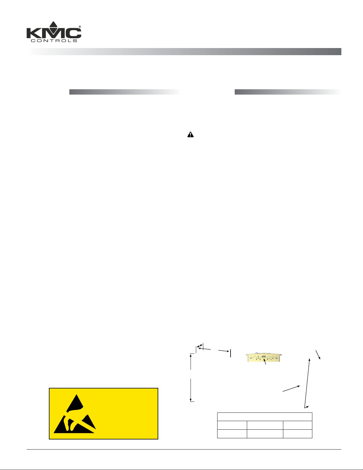
1. Complete rough-in wiring at each location prior
to the FlexStat’s installation. Cable insulation
must meet local building codes.
CAUTION
To prevent mounting screw heads from touching
the circuit board in the thermostat, use only the
mounting screws supplied by KMC Controls.
Using other screws may damage the FlexStat.
Do not turn screws in farther than necessary to
remove the cover.
2. If the cover is locked on the backplate, turn the
hex screws in the boom and top of the FlexStat
CLOCKWISE until they (just) clear the cover.
(See Illustration 1.) Pull the cover away from the
backplate (mounting base).
3. Route the wiring through the backplate.
4. With the embossed “UP” and arrows toward the
ceiling, fasten the backplate to a wall electrical
box. This FlexStat mounts directly on vertical 2 x
4 inch boxes but requires an HMO-10000W wall
mounting plate for horizontal or 4 x 4 boxes.
5. Make connections to the terminal blocks. (See
Connections and Wiring on page 5.)
6. Push the FlexStat cover over the backplate while
being careful not to pinch or dislodge any
wiring. Back the hex screws (counterclockwise)
out of the brackets until they engage the FlexStat
cover and hold it in place.
A
C
Embossed “UP” indicator
Additional Resources ............................................12
Important Notices ................................................. 12
B
NOTICE
OBSERVE PRECAUTIONS
FOR HANDLING
ELECTROSTATIC
SENSITIVE DEVICES
Illustration 1—Dimensions and Installation
BAC-120063CW-ZEC FlexStat 1 Installation and Configuration Guide, Rev. G
A B C
1.125 (29) 5.551 (141) 4.192 (106)
EIA-485 data
port (for quick
network access)
Terminal blocks
on backplate
Cover locking hex screws
Dimensions in Inches (mm)
Page 2

Application Overview
Return Air
Supply Air
from RTU
Optional Bypass Damper
MS/TP Network
24 VAC
Roof Top Unit
(RTU)
CSP-4702
To HI
Port
Optional Static Pressure Signal and Setpoint
STE-140x
Temp
Sensor
Input from DAT
Output to RTU
SSS-101x Flow Sensor
1/4"
Tubing
Displayed
RTU Controller—MAC 20, Device Instance 1000000
VAV B ox
SSS-101x Flow
Sensor
STE-140x Temp
Sensor
Supply Air
To Low Pressure Port
on Pitot Tube
OR
to H or L Port on
SSS-100x Sensor
(Mounted Perpendicular
to Air Flow)
MS/TP Network
DAT
FlexStat
Supply Air
to Room
Supply Air
from RTU
1/4" Tubing
Ethernet Cable (Up to 75 Feet Long)
STE-8x01 Room Temp Sensor
and Configuration Tool
Zone 1—MAC 3, Device Instance 1000001
MS/TP Network
SSS-101x Flow
Sensor
1/4" Tubing
Ethernet Cable (Up to 75 Feet Long)
STE-8x01 Room Temp Sensor
and Configuration Tool
SimplyVAV
24 VAC
(Alternate STE-601x Room
Temperature Sensor)
VAV B ox
STE-140x Temp
Sensor
Supply Air
to Room
SimplyVAV
24 VAC
(Alternate STE-601x Room
Temperature Sensor)
Zone 16—MAC 19, Device Instance 1000016
Illustration 2—Sample Networked RTU Installation
BAC-120063CW-ZEC FlexStat 2 Installation and Configuration Guide, Rev. G
Page 3
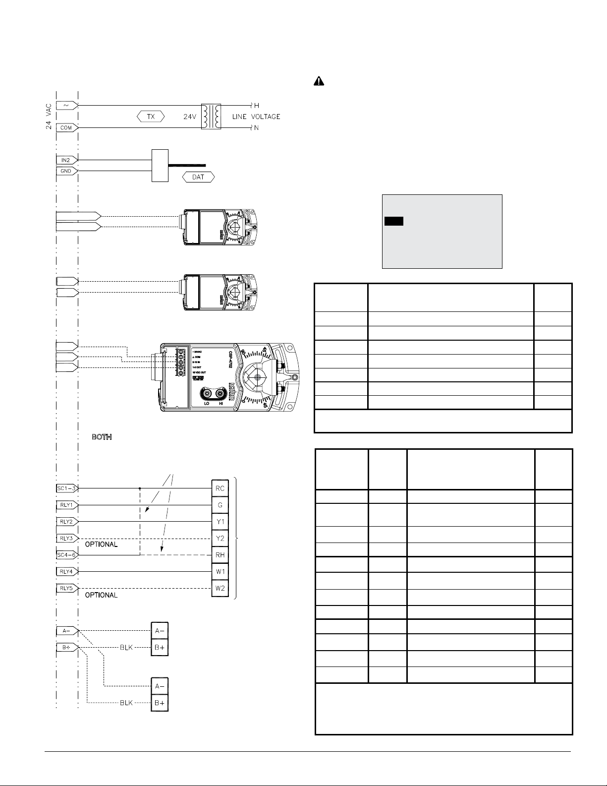
Roof Top Unit (RTU)
(1 or 2 Heat and 1 or 2 Cool)
XEE-6111-050 or XEE-6112-50 Transformer
CAUTION
Relays are for Class-2 voltages (24 VAC) only. Do not
connect line voltage to the relays!
Do not mistakenly connect 24 VAC to an analog
output ground.
STE-140x Duct Sensor, Type III
Optional Outside Air Damper
AO9 or Relay 6
GND or SC
Optional Heating/Cooling Coil Valve
AO8
GND
Optional Static Pressure Reading/Setpoint from/to CSP-4702
GND
AO7
IN9
TERMINALS
IF BOTH RC AND RH TERMINALS ARE PRESENT:
WIRE RC TO SC 1-3 AND RH TO SC 4-6.
IF ONLY ONE “R” TERMINAL IS PRESENT:
WIRE BOTH SC 1-3 AND SC 4-6 TO R.
NOTE: Althoughtypicalterminalcodeleersare
shown, check the schematics of your unit
for wiring details!
APPLICATION
DEGREES SCALE: °F
APP:
ROOF TOP
OPT: 1H/1C
ADDITIONAL SETUP
ZONE
Input
Terminals
IN9 Static Pressure Feedback (Optional) AI9
IN8 (Unused in this application) AI8
IN7 (Unused in this application) AI7
IN4 (Unused in this application) AI4
IN3 (Unused in this application) AI3
GND Ground
IN2 DAT * AI2
*NOTE: The DAT sensor is congured for IN2 in the ADVANCED >
APPLICATION > ADDITIONAL SETUP > SENSORS menu.
Output
Terminals
Typical
Terminal
Codes
RTU Input Connections
RTU Output Connections
(1 or 2 H and 1 or 2 C)
BACnet
Objects
BACnet
Objects
Analog 9 O. A. Damper (Optional) AO9
Ground
Optional Network
From
Previous
Network
Device
To
Next
Network
Device
RTU
Terminals
GND
Analog 8 Heat or Cool Valve (Optional) AO8
Analog 7 Static Pressure Setpoint (Optional) AO7
Relay 6 O. A. Damper (Optional) BO6
SC 4–6 RH/R 24 VAC (for Relay terminals 4–6)
Relay 5 W2 Heat 2 (Optional) BO5
Relay 4 W1 Heat 1 BO4
Relay 3 Y2 Cool 2 (Optional) BO3
SC 1–3 RC/R 24 VAC (for Relay terminals 1–3)
Relay 2 Y1 Cool 1 BO2
Relay 1 G Fan BO1
NOTE: Connections above are for rmware R2.0.0.4 and later. Earlier
rmware had the optional static pressure setpoint on Analog Output
9 instead of Analog Output 7, and it did not have the heating/cooling
coil valve option (Analog Output 8) or outside air damper (economizer)
option (Analog Output 9 or Relay 6).
(for Analog Output terminals 7–9)
Illustration 3—RTU Application Connections
BAC-120063CW-ZEC FlexStat 3 Installation and Configuration Guide, Rev. G
Page 4
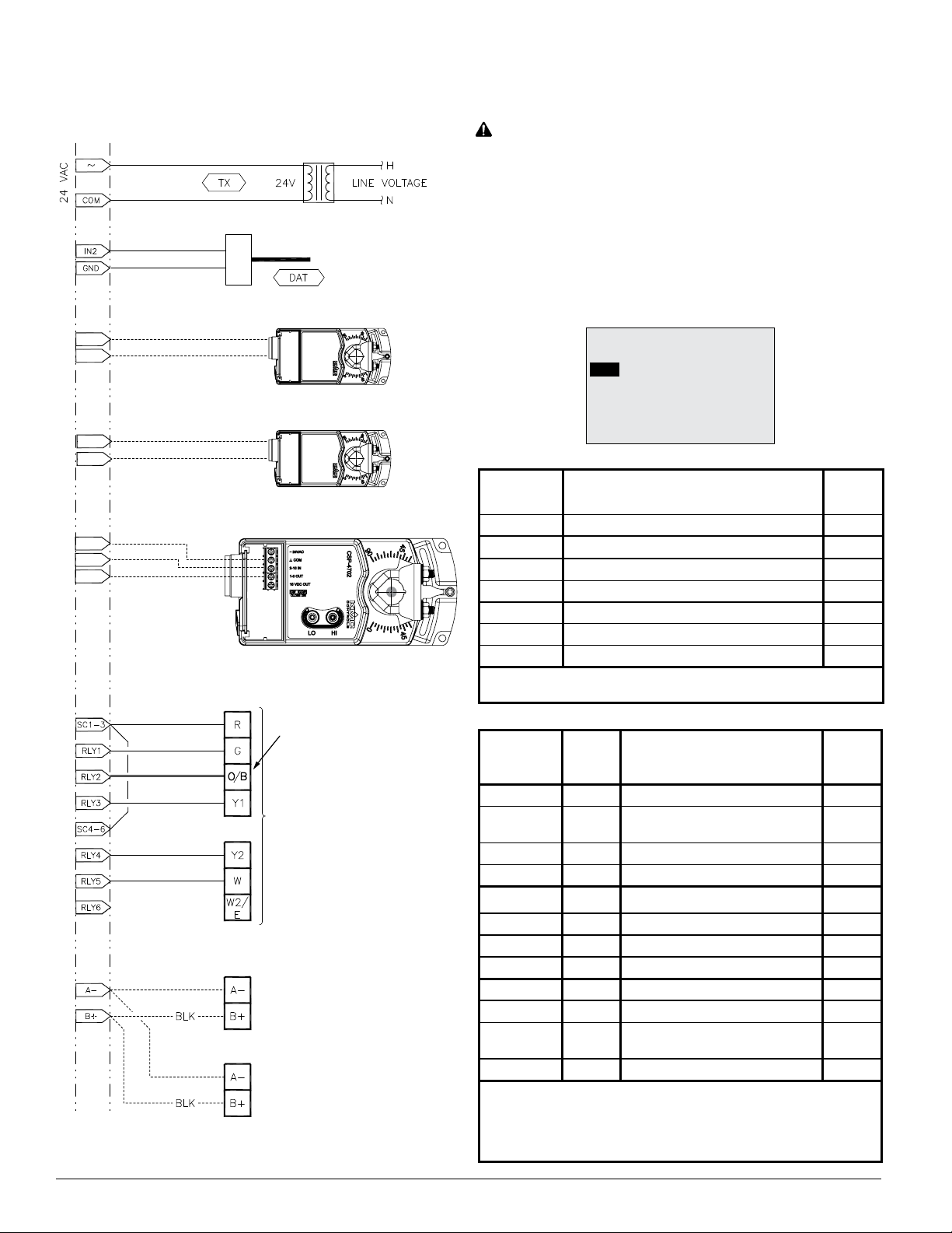
Heat Pump Unit (HPU)
1 or 2 Compressors with Auxiliary and Emergency Heat
XEE-6111-050 or XEE-6112-50 Transformer
STE-140x Duct Sensor, Type III
Optional Outside Air Damper
AO9
GND
Optional Heating/Cooling Coil Valve
AO8
GND
Optional Static Pressure Reading/Setpoint from/to CSP-4702
GND
AO7
IN9
TERMINALS
NOTE: Wire to “O” terminal if
reversing valve is energized in
cooling mode; wire to “B”
terminal if reversing valve is
energized in heating mode.
HPU
Terminals
From
Previous
Network
Device
Optional Network
To
Next
Network
Device
Illustration 4—HPU Application Connections
CAUTION
Relays are for Class-2 voltages (24 VAC) only. Do not
connect line voltage to the relays!
Do not mistakenly connect 24 VAC to an analog
output ground.
NOTE: Althoughtypicalterminalcodeleersare
shown, check the schematics of your unit
for wiring details!
APPLICATION
DEGREES SCALE: °F
APP:
HEAT PUMP
OPT: 1 STAGE
ADDITIONAL SETUP
ZONE
Input
Terminals
HPU Input Connections
IN9 Static Pressure Feedback (Optional) AI9
IN8 (Unused in this application) AI8
IN7 (Unused in this application) AI7
IN4 (Unused in this application) AI4
IN3 (Unused in this application) AI3
GND Ground
IN2 DAT * AI2
*NOTE: The DAT sensor is congured for IN2 in the ADVANCED >
APPLICATION > ADDITIONAL SETUP > SENSORS menu.
Output
Terminals
Typical
Terminal
Codes
HPU Output Connections
Analog 9 O. A. Damper (Optional) AO9
GND
(for Analog Output terminals 7–9)
Ground
Analog 8 Heat or Cool Valve (Optional) AO8
Analog 7 Static Pressure Setpoint (Optional) AO7
Relay 6 W2/E Emergency Heat (Optional) BO6
SC 4–6 R 24 VAC (for Relay terminals 4–6)
Relay 5 W Auxiliary Heat (Optional) BO5
Relay 4 Y2 Compressor 2 (Optional) BO4
Relay 3 Y1 Compressor 1 BO3
SC 1–3 R 24 VAC (for relay terminals 1–3)
Relay 2 O/B
Reversing Valve
(see O/B Note in schematic)
Relay 1 G Fan BO1
NOTE: Connections above are for rmware R2.0.0.4 and later. Earlier
rmware had the optional static pressure setpoint on Analog Output
9 instead of Analog Output 7, and it did not have the heating/cooling
coil valve option (Analog Output 8) or outside air damper (economizer)
option (Analog Output 9).
BACnet
Objects
BACnet
Objects
BO2
BAC-120063CW-ZEC FlexStat 4 Installation and Configuration Guide, Rev. G
Page 5

Connections and Wiring
Wiring Considerations
• Because of the many connections (power,
network, inputs, outputs, and their respective
grounds or switched commons), be sure wiring
is well planned before installation of conduit!
• Make sure that conduit for all wiring has adequate diameter for all necessary wiring. Using
1-inch conduit and junction boxes is recommended! Use external junction boxes above the ceiling
or in another convenient location as needed
to make connections that run to the FlexStat’s
junction box.
• To prevent excessive voltage drop, use a conduc-
tor size that is adequate for the wiring length!
Allow plenty of “cushion” to allow for transient peaks during startup.
• Using multiple conductor wires for all relevant
inputs and outputs is recommended. Grounds
for all the inputs can be combined on one wire.
CAUTION
Do not mistakenly connect 24 VAC to an analog
output ground. This is not the same as a relay’s
switched common. See the backplate’s terminal
label for the correct terminal.
CAUTION
Relays are for Class-2 voltages (24 VAC) only. Do not
connect line voltage to the relays!
CAUTION
To avoid damage from ground loops and other
communication issues in networked FlexStats,
correct phasing on MS/TP network and power
connections on ALL the networked controllers is
critically important.
NOTE: IN1 and IN5–6 are
reserved for internal sensors
Inputs
(Wiring is
dependent on
application)
MS/TP
Network
Inputs
24 VAC
Common/–/C
Phase/ /R
Illustration 5—Terminals and Connections
IN9
IN8
GND
IN7
+B
–A
IN4
IN3
GND
IN2
NOTE: SC = Switched
(relay) Common
Outputs
Analog 9
GND 7–9
Analog 8
Analog 7
Relay 6
SC 4–6
Relay 5
Relay 4
Relay 3
SC 1–3
(Wiring Cutout in Backplate)
Relay 2
Relay 1
Output Connections
Connect the device under control between the desired
output terminal and the related SC (Switched Com-
mon for relays) or GND (Ground for analog outputs)
terminal. (See Illustration 5).
Optional connections (for rmware R2.0.0.4 and later)
are:
• A static pressure setpoint signal to a CSP-4702
pressure controller used with the system for
pressure bypass control on AO7. (Earlier rmware
had it on AO9 instead.) The static pressure feedback signal is on AI9. The setpoint value can be
changed in the Setpoints menu.
• Outside air damper (economizer) on AO9 with
the Additional Setup menu options of None,
Modulating, Disable/Enable. Connect to AO9 for
modulating or (on RTU only) BO6 for enable/
disable.
• A modulating valve on a hot or cold water coil on
AO8. This can provide primary or supplemental
modulating heating or cooling to the staged
heating or cooling. The Additional Setup menu
options for actuator device type are 0–10, 10–0,
2–10, or 10–2 VDC.
BAC-120063CW-ZEC FlexStat 5 Installation and Configuration Guide, Rev. G
Page 6

One Switched
Common
Connection
Per Bank of
Three
Normally
Open Relays
Relay 3 (or 6)
SC (Phase) 1–3 (or 4–6)
Relay 2 (or 5)
Relay 1 (or 4)
NOTE: Type II or III 10K ohm thermistors can be
selected by changing the menu seing in
ADVANCED > INPUTS (see Conguration
and Operation on page 7).
NOTE: FlexStat inputs do not support 1K ohm
RTDs.
Illustration 6—Switched (Relay) Common and Relays
For the bank of three relays, there is one Switched
(relay) Common connection (in place of the GND terminal used with analog outputs). (See Illustration 6.)
For the relay circuit, the phase side of the AC should
be connected to the SC terminal.
FlexStat relays are NO, SPST (Form “A”).
Donotaachadevicethatdrawscurrentexceeding
the FlexStat’s output capacity:
• Maximum output current for individual ANALOG outputs (7–9) is 20 mA @ 12 VDC (each).
• Max. output current is 1 A for individual RELAYS @ 24 VAC/VDC or a total of 1.5 A per bank
of 3 relays (relays 1–3 and 4–6).
Input Connections
Passive input devices require pull-up resistors in the
circuit. For a passive input device (a DAT 10K ohm
thermistor on IN2), set (if not in the default position)
the pull-up switches on the back of the circuit board
to the 10K ohm position, with the upper switch to the
left and lower switch to the right. (See Illustration 8.)
NOTE: IN2mustalsobeconguredinthemenufor
DAT. See Conguration and Operation on
page 7.
For an active voltage device (optional 1–5 VDC static
pressure reading from a CSP-4702 on IN9), set the
switches to the 0–12 VDC position, with the upper
switch to the right and lower switch to the left.
NOTE: Unlike the EOL switch pairs, the INPUT
switch pairs must NOT have both switches
set to the same direction—if one of the
pair’s switches is set to the left, for example,
the other must be set to the right (or vice
versa). ALL the input pull-up resistor
switch pairs must be fully latched in either
10K Ohm or 0–12 VDC position even if
a switch pair has no input connected! A
single incorrect switch position may cause
errors in multiple inputs.
Power Connection
Connect a KMC Controls 24 volt, Class-2 transformer
to the power terminals on the FlexStat’s backplate:
1. Connect the transformer’s neutral lead to the 24
VAC Common/–/C terminal. (See Illustration 5.)
2. Connect the AC phase lead to the 24 VAC
Phase/
~/R terminal.
Power is applied to the FlexStat when the transformer is powered.
KMC Controls recommends powering only one controller/thermostat from each transformer. If installing
a FlexStat in a system with other controllers/thermostats powered from a single transformer, however,
phasing must be correct and the total power drawn
from the transformer must not exceed its rating.
Network Wiring
For an MS/TP network, use a three-conductor cable
(Belden cable #82760 or equivalent):
1. Connect the –A terminals in parallel with all
other –A terminals on the network. (See Illustrations 2 through 5.)
2. Connect the +B terminals in parallel with all
other +B terminals.
3. Connect the shields of the cable together at each
device. Use a wire nut at the FlexStat or the S
terminal in KMC BACnet controllers. Connect
the cable shield to a good earth ground at one
end only.
NOTE: The S terminal in KMC controllers is
provided as a connecting point for the
shield. The terminal is not connected to the
ground of the controller. When connecting
to controllers from other manufacturers,
verify the shield connection is not
connected to the controller’s ground.
NOTE: For more information on principles and
good practices when connecting an MS/TP
network, see Planning BACnet Networks
(Application Note AN0404A).
BAC-120063CW-ZEC FlexStat 6 Installation and Configuration Guide, Rev. G
Page 7

Network EOL (End-Of-Line) Termination
The controllers/thermostats on the physical ends of
an EIA-485 wiring segment must have end-of-line
termination installed for proper network operation.
(See Illustrations 7 and 8.) If a FlexStat is at the physical end of the MS/TP network line, set both the EOL
termination switches to On (to the right) on the back
of the circuit board. If not on the end, ensure that
both switches are O (to the left).
Configuration and Operation
WED 7/30 5:33 PM
DAT
Zone Information (# of
Zones, # of Zones Calling
for Cooling, and # of Zones
Calling for Heating)
COOL:
OCC:
FAN:
COOL CALLS 5
Up
Illustration 7—MS/TP Network End-Of-Line Termination
Input Pull-Up Switches
10K Ω
0-12 V
IN9
EOL Switches
OFF
ON
IN8
Switch
Pushed
Left
Switch
Pushed
Right
IN7
IN4
IN3
IN2
NOTE: EOL = End
Of Line of BACnet
MS/TP network.
NOTE: 10K Ω inputs
are configurable for
Type II or Type III
thermistors in
FlexStat’s menu.
Illustration 8—EOL/Pull-Up Switch Positions
Left
(Override)
Down
Right
(Menu)
Illustration 9—FlexStat Display and Button Functions
NOTE: For additional information, see the relevant
partsoftheCongurationsectioninthe
FlexStat Operation Guide (but not all
things apply to this model).
NOTE: Seings and adjustments may require a
password.
Configure the Application and Address
Toaccessthemenus,presstherightbuon.Navigate
themenusandchangeseingsbypressingacombinationofbuons. Press the:
• Enter buon to select and/or exit value editing.
• Up/Down buon to move among entries (up/
down lines).
• Left/Right buon to move among valueelds
(left/right spaces).
• Left buon to return to the Home screen.
Congure the application through the menu system.
From the Main Menu, select ADVANCED (enter
password if needed) and then APPLICATION.
APPLICATION
DEGREES SCALE: °F
APP:
ROOF TOP
OPT: 2H/2C
ADDITIONAL SETUP
ZONE DEV INS RANGE
BAC-120063CW-ZEC FlexStat 7 Installation and Configuration Guide, Rev. G
ADDITIONAL SETUP
DAMPER
FAN
SENSORS
ZONE HYSTERESIS: 2
VALVE HT OR CL: HEAT
DEVICE TYPE: 0-10V
STAGING
Page 8

NOTE: The BAC-120063CW-ZEC FlexStat comes
preconguredfora2H/2CRTUandzone
device number range of 1000000 through
1000016.
Select:
1. APP: ROOF TOP or HEAT PUMP.
2. OPT: Match stages of heating and cooling to the
RTU or HPU.
3. Under ADDITIONAL SETUP > SENSORS,
change IN2 from NONE to DAT.
SENSORS
IN2:
DAT
NOTE: The default Type III (10K ohm) thermistor
seing for DAT can be changed to Type II
(if needed) in ADVANCED > INPUTS > 2:
DISCH AIR TEMP > SENSOR: >.
INPUT #2
DISCH AIR TEMP
VALUE: 55.0°F
CAL. OFFSET: 0.0
OUT-OF-SERVICE: FALSE
FILTER WEIGHT: 6
SENSOR:
>
10K TYPE III
4. Under ADDITIONAL SETUP, change other
defaults if needed.
5. Under ZONE DEV INS RANGE, the default base
zone device numbers (with up to 16 zones of SimplyVAV controllers) start at 1000001 as a default.
To change the default base numbers to 2000001,
3000001, or 4000001, select the desired range.
ZONE DEVICE INSTANCE
RANGE:
1M = 1000001–1000016
2M = 2000001–2000016
3M = 3000001–3000016
4M = 4000001–4000016
1M
To set the FlexStat’s BACnet Device Instance (and
optionally name and location):
1. Select ADVANCED (enter password if needed)
and then DEVICE.
2. Change (or conrm) INSTANCE to 1000000.
DEVICE
INSTANCE:
NAME: ZEC_FlexStat_1
LOCATION: KMC Controls
1000000
To congure the MAC address, from the Main Menu,
select ADVANCED (enter password if needed) and
then COMMUNICATIONS.
COMMUNICATIONS
ACTIVE:
STATUS: ACTIVE
ETHERNET SETTINGS
IP SETTINGS
FOREIGN DEV SETTINGS
MS/TP SETTINGS
CONFIGURE
COMMUNICATIONS
ACTIVE:
STATUS: ACTIVE
MAC ADDRESS: 20
BAUD: 38400
AUTO-BAUD: OFF
MAX MASTER: 20
MS/TP
To set protocol and parameters for BACnet communications:
1. Select ACTIVE: CONFIGURE.
2. Select MS/TP SETTINGS.
3. Change MAC ADDRESS to 20 (if needed).
4. Change MAX MASTER to 20 (or other relevant
number depending on network).*
5. Select ACTIVE: MS/TP and restart the FlexStat.
*NOTE: For a network of 16 SimplyVAV controllers,
seing the Max Master to 20 will make
the network more ecient and perform
faster. For network connections to larger
networks with other equipment, the MAC
address should be the same as the largest
MAC address in the network for maximum
performance.
NOTE: If the Zone Device Instance range is
changed from the default, change the
FlexStat’s Device Instance to correspond
with the range (e.g., 3000000 for a range of
NOTE: ACTIVE: CONFIGURE must FIRST BE
SELECTED before any of the values can be
changed! Otherwise values are read only.
Setpoints
3000001—3000016).
If the controllers are going to be networked, congure the system address as needed and make note of
the FlexStat MAC and Device Instance. If the system
is stand-alone, address the FlexStat for MAC 20,
The home screen displays the DAT in large numbers
(instead of room temperature that FlexStats normally
display). To change the heating and cooling DAT
setpoints, under the Main Menu, select SETPOINTS.
Device Instance 1000000. (See Illustration 2.)
BAC-120063CW-ZEC FlexStat 8 Installation and Configuration Guide, Rev. G
Page 9

SETPOINTS
COOL DAT SETPOINT:
HEAT DAT SETPOINT: 130° F
DUCT ST STPT: 0.5 in H2O
55° F
that one day in the Individual Days menu
may be easier (two entries) than entering
schedules for each day separately in the
Individual Days menu (ve entries).
The optional duct static pressure setpoint is also in
this menu.
NOTE: The airow minimum limit in each
SimplyVAV controller needs to be at least
10 cfm (and 25 cfm is recommended).
Otherwise, the controller will not properly
sense the local duct DAT during minimum
ow. See BAC-8000 series for more
information about the controller-actuators.
Heat/Cool, Fan, Occupancy, and Override
When the fan is commanded to run, the animated
“FAN” icon on the display rotates. When the fan
command stops, the fan icon is motionless.
The “OCC” icon shows a sun when in Occupied
mode and a quarter moon when in Unoccupied
mode.
HEAT or COOL will show (and be animated when
there is an active command to move the temperature
toward the setpoint via mechanical heating/cooling
or an economizer), depending on the current mode.
This can also be turned OFF.
To override these modes from the Home (temperature display) screen, press the Left arrow buon.
Press Up or Down to get to the desired line and then
Enter (twice) to edit the mode seing. Press Left to
exit to Home.
Schedules
SCHEDULE
ENTIRE WEEK [MON–SUN]
WEEKDAYS [MON–FRI]
WEEKEND [SAT–SUN]
INDIVIDUAL DAYS
HOLIDAYS
ENTIRE WEEK
1:
7:30:00 AM ON
2: 5:15:00 PM OFF
3:
4:
5:
6:
[—>] DELETES ENTRY
NOTE: The last overlapping entry overrides
any other. For example, suppose the
WEEKDAYS menu is used to set all
weekdays for 7:00 AM ON and 5:00 PM
OFF, and then the INDIVIDUAL DAYS
menu is used to add some additional
evening meeting ON times for Tuesday
and Wednesday. If the WEEKDAYS menu
is later used to change the ON time from
7:00 to 7:15, schedules for all the individual
week days will be reset to conform to
what appears in the WEEKDAYS menu
and any special times for individual days
will be erased. (Special day schedules will
then need to be added again through the
INDIVIDUAL DAYS menu).
The Holiday entries will override the normal occupied weekly schedule entries and keep those days’
seings at their setback values. (Setback values are
entered in the Setpoints section of the Main Menu.)
HOLIDAYS
HOL1:
JAN 1 2017
HOL2: APR 14 2017
HOL3: MAY 29 2017
HOL4: JULY 4 2017
HOL5: SEPT 4 2017
HOL6: NOV 23 2017
HOL7: NOV 24 2017
NOTE: See the FlexStat Operation Guide for more
information on generic FlexStat operation.
Trends
The BAC-120063CW-ZEC Flexstat is precongured
for the following trend logs:
1. DAT (AI2 sampled at 30 second intervals).
2. DAT (at 1 minute intervals).
3. DAT (at 5 minute intervals).
4. Number of zones (AV22 at 1 minute intervals) of
SimplyVAVs.
The factory default schedule is always occupied
(ON). To modify the schedule for mixed occupied
(ON) and unoccupied (OFF) times, select Schedules
in the Main Menu.
NOTE: If a day of a week (e.g., Friday) has a
dierent schedule than the rest, using the
Weekdays menu rst and then modifying
BAC-120063CW-ZEC FlexStat 9 Installation and Configuration Guide, Rev. G
5. Number of calls for cooling (AV24 at 1 minute
intervals) from SimplyVAVs.
6. Number of calls for heating (AV25 at 1 minute
intervals) from SimplyVAVs.
7. Duct static pressure (AV103 at 1 minute intervals)
from an optional CSP-4702.
8. Duct static pressure setpoint (AV104 at 1 minute
Page 10

intervals) to an optional CSP-4702.
The Trend Viewer is available in the Main Menu to
view the (last 256 samples of) data in tabular format.
Software, such as KMC Connect or TotalControl, can
view the trend objects as graphs as well as change
the interval as desired.
The dierent sampling rates allow a “longer” or
“ner resolution” view of the trends. The default
sampling intervals can be changed by the user in
ADVANCED > DEVICE.
NOTE: The faster the sampling rate, the faster the
256 samples are lled and the values start
over.
NOTE: The FlexStat menu allows seing of
intervals only in multiples of 1 minute (not
seconds). If you change a default “seconds”
interval in the menu, you will not be able to
set it back to the original without a factory
reset or BAS software.
Zone Hysteresis (Changeover)
In the Additional Setup menu, the Zone Hysteresis
value (AV102) is the number of controllers (above
50% of the total) required for “majority rule” in
changing heating/cooling modes for the RTU or
HPU. The default is 1. For an explanation of this
changeover seing option, see Sequence of Operation
on page 10.
NOTE: Firmware earlier than R2.0.0.4 did not have
this option.
Zone Status
In the lower right of the home screen, smaller leers
show, in rotation:
• The detected number of connected zones of
SimplyVAVs.
• The number of zones calling for cooling.
• The number of zones calling for heating.
NOTE: After power-up or restarting of the FlexStat
and/or SimplyVAVs, the zone numbers
require several minutes to show correct
values.
For more detailed information, under the Main
Menu, select ZONE STATUS to view the status of all
connected zones. Options for each zone’s values are:
• Call for Cooling
• Call for Heating
• No Call for Either
• No Communication with a Zone (either there is a
communication problem with a zone or no zone
is connected)
The Zone Status screen also shows the Duct Status
pressure.
Sequence of Operation
NOTE: The HPU and RTU sections of the FlexStat
Application Guide have some basic
generic information about HPU and RTU
operation.
The BAC-120063CW-ZEC FlexStat determines RTU/
HPU heating or cooling mode by “majority rule”
of the number of heating and cooling calls from the
SimplyVAV controllers. If the number of heating and
cooling calls is equal, the previous mode is maintained.
The number of controllers above 50% of the total re-
quired for changeover to the other mode is controlled
by Zone Hysteresis (in the Additional Setup menu).
For the default seing of 1, a majority by one control-
ler will cause the mode to switch. For example, 8
controllers calling for heating versus 7 controllers
calling for cooling will change the RTU/HPU mode
from cooling to heating.
NOTE: If Zone Hysteresis is changed to 2, then
heating/cooling mode maintains the
previous mode until there are two more
zones needing the opposite mode than
those needing the current mode. Increasing
the number can be helpful if the system
seems to be switching modes back and
forth too quickly. The maximum hysteresis
value is 16.
NOTE: See Zone Hysteresis (Changeover) on page
10 and Congure the Application and
Address on page 7.
In RTU/HPU heating mode, the heating setpoint and
the cooling setpoint are both set to 110°. In RTU/
HPU cooling mode, the heating setpoint and the
cooling setpoint are both set to 55°. If there is no call
for heating or cooling (all VAV boxes are satised),
the cooling setpoint is set to 110° and the heating
setpoint is set to 55°.
During a scheduled O time, the RTU/HPU fan does
not run unless there is a call for heating or cooling.
BAC-120063CW-ZEC FlexStat 10 Installation and Configuration Guide, Rev. G
Page 11

Troubleshooting
Customization
• For optimal temperature control, all spaces
within a particular zone should be exposed to
similar environmental factors (e.g., all border a
perimeter wall or all be within insulated interior
spaces). Otherwise, for example, depending on
the weather, perimeter spaces may consistently
need heating when interior spaces consistently
need cooling.
• The DAT sensor must be properly connected and
congured. See Input Connections on page 6
and Congure the Application and Address on
page 7.
• The Device Instance of the FlexStat should
correspond with the Device Instance range of the
SimplyVAVs. See Congure the Application and
Address on page 7.
• Check the wiring. See Wiring Considerations on
page 5, Output Connections on page 5,
Input Connections on page 6, Power Connec-
tion on page 6, and Network Wiring on page
6.
Additional customization can be done using KMC
Connect, KMC Converge, or TotalControl. For example, a fan status switch (such as a KMC CSE-110x
or a CSE-120x) could be connected to IN3 (with the
appropriate pull-up switch seing) and the following
code could be run in Program 9 or 10.
REM FAN STATUS
REM A Normally Open dry contact
switch is connected to AI3 (with
pull-up switch set to 10K ohms)
REM BV16 shows Active when switch is
closed (fan running) and Inactive
when switch is open (not running)
IF AI3 < 0.5 THEN BV16 = 1 ELSE BV16
= 0
NOTE: Set the program to Run on Cold Start, save
it, and restart the FlexStat.
The value of BV16 (active or inactive) could then be
displayed on a card in the KMC Commander interface or a TotalControl graphics page.
• Check EOL switches. See Network EOL (End-Of-
Line) Termination on page 7.
• See also Zone Status on page 10.
• See also Setpoints on page 8.
• See also Schedules on page 9.
• See also Zone Hysteresis (Changeover) on page
10.
• See also Sequence of Operation on page 10.
• See the relevant parts of the Troubleshooting
section in the FlexStat Operation Guide.
Maintenance
Remove dust as necessary from the holes in the top
and boom. Clean the display with a soft, damp
cloth and mild soap.
Remote (BAC-5051E) Interface
The BAC-5051E BACnet router provides a means of
remotely monitoring and changing the conguration
of the zoning system with a web browser. For more
information, see the BAC-5051E Router Application
and Installation Guide.
BAC-120063CW-ZEC FlexStat 11 Installation and Configuration Guide, Rev. G
Page 12

IoT (KMC Commander) Interface
Additional Resources
KMC Commander provides an easy setup and
interface of zoning (via web page or phone app) with
remote monitoring and control, scheduling, trends,
alarms, and integration with other IoT (Internet of
Things) devices. For information, see VAV and IoT
RetrotsforVVTApplicationGuide.
See additional information about this model FlexStat
on the BAC-120063CW-ZEC web page.
For general operation, conguration, troubleshooting, and other information, see the (generic) FlexStat
Operation Guide and FlexStat Application Guide.
See also the BAC-8000 series for information about
the VAV controller-actuators.
See also the CSP-4702 page for information about the
dierential pressure controller/actuator.
For remotely monitoring and changing the
conguration, see the BAC-5051E Router
Application and Installation Guide.
For IoT use with KMC Commander, see VAV and
IoTRetrotsforVVTApplicationGuide.
Important Notices
The material in this document is for information
purposes only. The contents and the product it
describes are subject to change without notice.
KMC Controls, Inc. makes no representations or
warranties with respect to this document. In no event
shall KMC Controls, Inc. be liable for any damages,
direct or incidental, arising out of or related to the
use of this document.
This device complies with Part 15 of the FCC Rules.
Operation is subject to the following two conditions:
(1) this device may not cause harmful interference,
and (2) this device must accept any interference
received, including interference that may cause
undesired operation. A BAC-12xxxx Class B digital
apparatus complies with Canadian ICES-003.
KMC Controls, Inc.
19476 Industrial Drive
New Paris, IN 46553
574.831.5250
www.kmccontrols.com
info@kmccontrols.com
BAC-120063CW-ZEC FlexStat 12 Installation and Configuration Guide, Rev. G
© 2019 KMC Controls, Inc. 913-019-30G
 Loading...