

Page 1
Contents
Minimum Requirements ................................................1
Select a Location .........................................................1
Initial Setup ................................................................2
Unboxing .............................................................2
Installation ...........................................................3
Prepare the Panel ..................................................3
Install the Mounting Plate .......................................3
Mount the Power Suppy to the Panel . .................... 4
Mount the USB-to-Ethernet Adapter to the Panel ........4
Connect the Power ................................................5
Mount the Tablet Assembly to the Panel ....................6
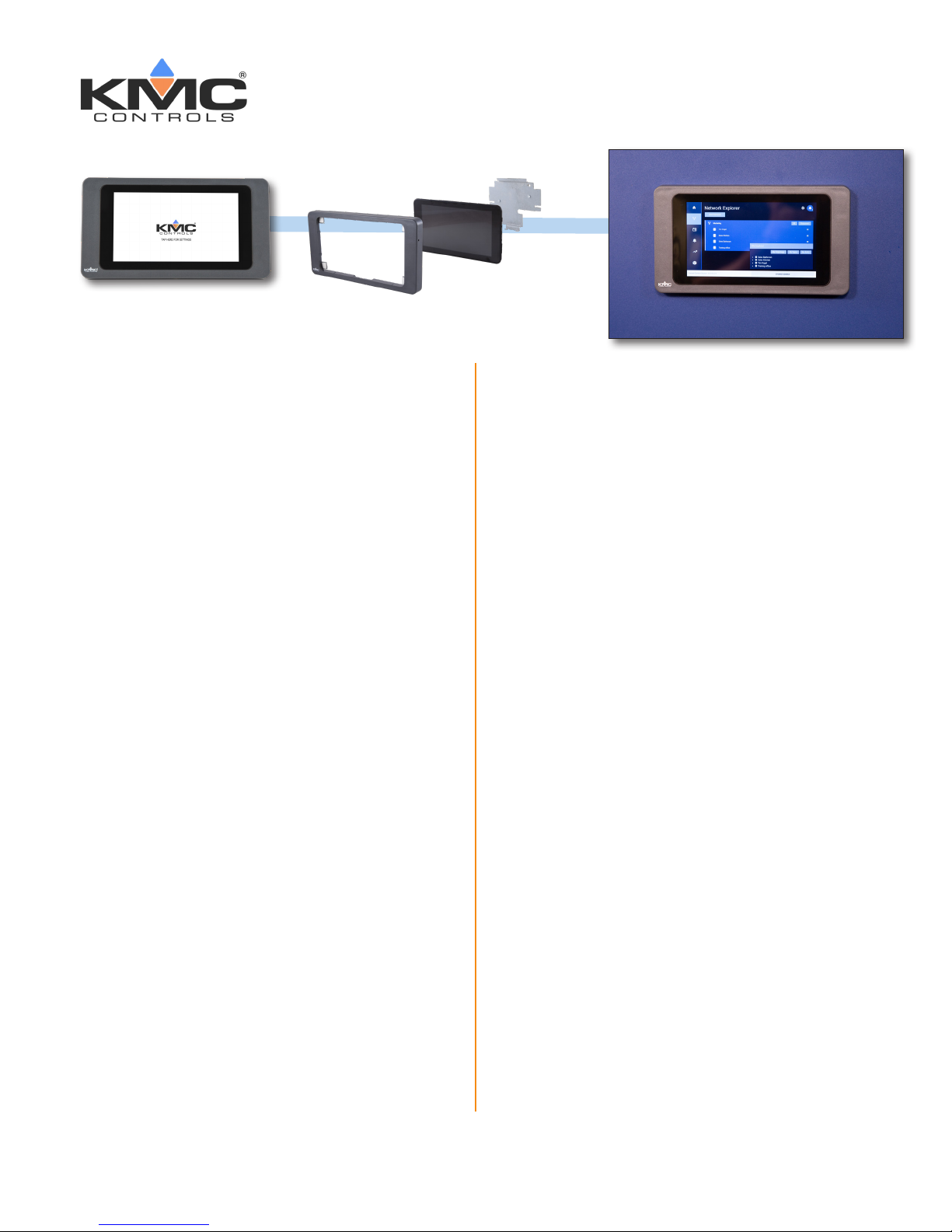
7" Touch Screen Display
Installation Guide
Minimum Requirements
Installation requires the following minimum
hardware and connections:
7" Touch Screen Display (P/N DISPLAY-7)
tablet
Power source
USB-to-Ethernet adapter (for Ethernet
connection)
Mounting plate and hardware
Support Documents .....................................................7
Contact Information .....................................................7
Important Notices ........................................................7
Internet connection (via Wi-Fi or Ethernet
Cat-5 cable)
Information required to complete installation
includes:
The relevant network addresses and
information from the building’s IT
department
A list of all points in all controllers that
will be monitored
Select a Location
The 7" Touch Screen Display is designed to be
mounted to the surface of a standard electrical
panel.
Before installing the display:
1. Complete any preparation work to the panel.
KMC Controls, 19476 Industrial Drive, New Paris, IN 46553 / 877-444-5622 / Fax: 574-831-5252 / www.kmccontrols.com
2. Make sure there is proper grounding.
Page 2
Initial Setup
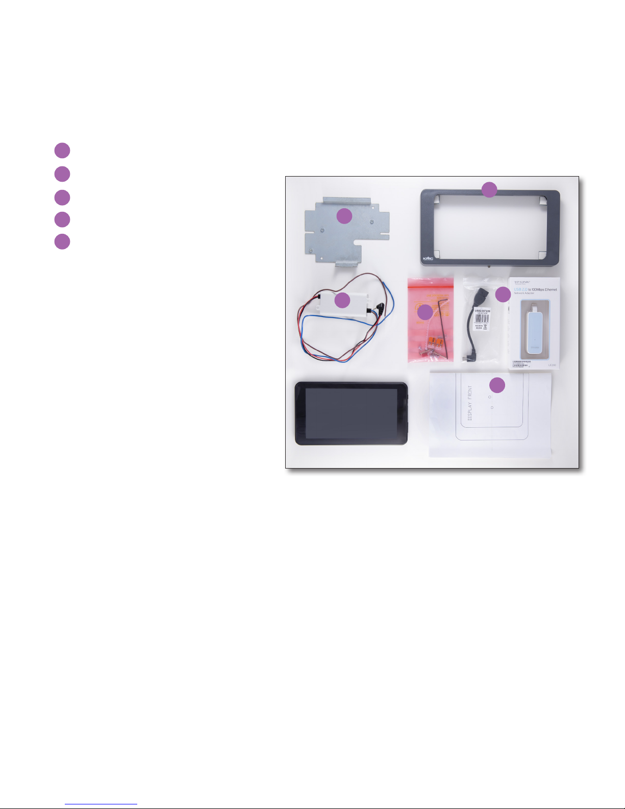
Unboxing
1. Remove the 7" Touch Screen Display tablet from the carton and place it temporarily in a secure area.
2. Verify that the included hardware is present. This includes:
(1) USB-to-Ethernet adapter (with micro USB connector cable)
A
(1) One switched-mode power supply
B
(1) Mounting plate and printed template
C
D
D
(1) Frame
E
(1) Plastic bag containing:
(1) ring wire grounding terminal
(1) plastic grommet strip
(2) lever-action wire terminals
(5) M3 x 6 mm x ¼ inch screws
(2) M3 x 6 mm x 1 inch screws
(2) nylon insert locking nuts
(2) clinch nuts
(2) serrated lock washers
(1) Allen wrench
C
B
E
A
C
NOTE: Do not discard the 7” Touch Screen Display Quick Start Guide included in the shipping carton.
It contains information on how to intially congure the device. (If it is lost, however, download the
most recent version from the KMC Partners site. Refer to Support Documents on page 7.)
KMC 7" Touch Screen Display Installation Guide 2 862-019-12B
Page 3
INSTALLATION
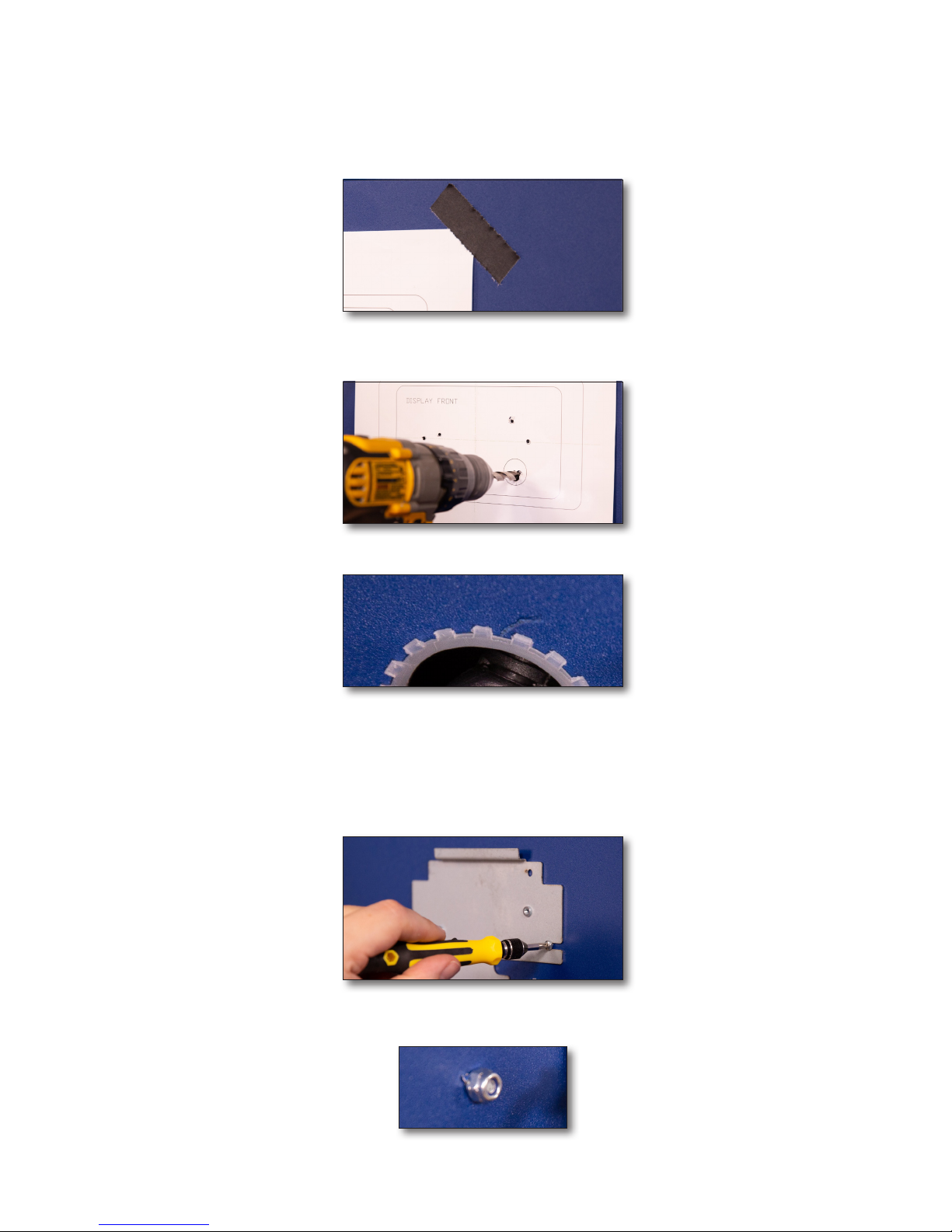
Prepare the Panel
1. Use tape to temporarily attach the mounting template to the desired location on the panel.
2. Drill the holes.
3. Fit the grommet strip along the edge of the 1 inch (26 mm) hole.
Install the Mounting Plate
Complete the following steps to attach the mounting plate to the panel.
1. Attach the mounting plate to the front of the panel using the two (2) 1-inch screws provided.
2. Place one nylon lock nut on the exposed end of each bolt and tighten against the back of the panel.
KMC 7" Touch Screen Installation Guide 3 862-019-12B
Page 4

Mount the Power Suppy to the Panel .
Complete the following steps to mount the power supply to the panel.
1. Align the bracket holes on the power supply with those matching on the back of the mounting plate.
2. Attach the power supply by placing one serrated lock washer onto each of the two (2) 6 mm screws and
inserting the assembly through the bracket and the back of the panel.
3. Place one clinch nut onto each exposed bolt and secure against the front of the plate.
Mount the USB-to-Ethernet Adapter to the Panel
NOTE: The following steps apply if an Ethernet connection will be used.
1. Attach the USB-to-Ethernet adapter to the back of the panel. The following example uses cable ties and
adhesive cable tie mounting pads (not incuded).
KMC 7" Touch Screen Display Installation Guide 4 862-019-12B
Page 5

2. Feed the the micro USB plug and power supply barrel plug through the 1 inch (26 mm) hole in the panel.
Connect the Power
Complete the following steps to connect the power supply to the power source and tablet.
WARNING: You can be killed or seriously injured if you contact live, high-voltage circuits. Follow
all local electrical codes and lock-out and tag-out procedures when connecting or working on
power supplies.
1. Open each terminal lever by pulling the free end of the tab away from the face of the terminal block.
2. Insert the end of the neutral (blue) wire into one port on one of the terminal blocks.
3. Close the tab to secure the wire.
4. Insert the end of the phase (brown) wire into one of the ports on the other terminal block.
5. Close the tab to secure the wire.
6. Insert the neutral wire from the connection to a 100–200 VAC power source into the other port on the neutral (blue) wire terminal block.
7. Close the tab to secure the wire.
8. Insert the phase wire from the connection to a 100–200 VAC power source into the remaining port on the
phase (brown) wire terminal block.
KMC 7" Touch Screen Display Installation Guide 5 862-019-12B
Page 6

9. Close the tab to secure the wire.
3. Connect the barrel plug from the power supply to the round socket on the right edge of the display.
4. Connect the micro USB plug from the USB-to-Ethernet adapter to the micro USB socket on the right edge of
the display.
NOTE: KMC Controls recommends setting up the tablet for use before mounting to the panel is completed.
Refer to the Quick Start Guide or User Guide for these procedures.
Mount the Tablet Assembly to the Panel
1. Temporarily remove two of the corner brackets along one edge of the frame. This provides room to insert
the tablet and power and communication cables.
2. Ease the display into the frame.
3. Re-attach the two corner brackets to secure the tablet to the frame.
4. Make sure that the power and micro USB cables are not dislodged or crimped.
5. Use the long groove along the top inside edge of the frame to align the display-frame assembly over the
mounting plate, swinging the assembly into place from the top.
6. Use the Allen wrench to tighten the set screw on the bottom of the assembly against the mounting plate.
KMC 7" Touch Screen Display Installation Guide 6 862-019-12B
Page 7

Support Documents
For the 7" Touch Screen Display Quick Start Guide, 7" Touch Screen Display User Guide, and 7" Touch Screen
Display Data Sheet, log on to the KMC Partners site (partners.kmccontrols.com) and type the part number
DISPLAY-7 in the Search eld.
NOTE:
Documents, product design, and product specications are subject to change without notice.
Contact Information
KMC Controls, Inc.
19476 Industrial Drive
New Paris, IN 46553
U.S.A.
TEL: 1.574.831.5250 or 877.444.5622
FAX: 1.574.831.5252
Email: info@kmccontrols.com
Web (Public): www.kmccontrols.com
Web (Partners): partners.kmccontrols.com
Important Notices
The material in this document is for information purposes only. The contents and the product it describes are
subject to change without notice.
KMC Controls, Inc. makes no representations or warranties with respect to this document. In no event shall
KMC Controls, Inc. be liable for any damages, direct, or incidental, arising out of or related to the use of this
document.
The KMC logo is a registered trademark of KMC Controls, Inc. All rights reserved.
KMC 7" Touch Screen Display Installation Guide 7 862-019-12B
 Loading...