

Page 1
Installation Guide
Manual Reset High Limit
CTE-6001
Mounting
1. Drill an opening in the supply air duct to accept
the 3/4" diameter sensor.
2. Mount the unit on the duct using three selftapping screws in the 7/32" diameter mounting
holes.
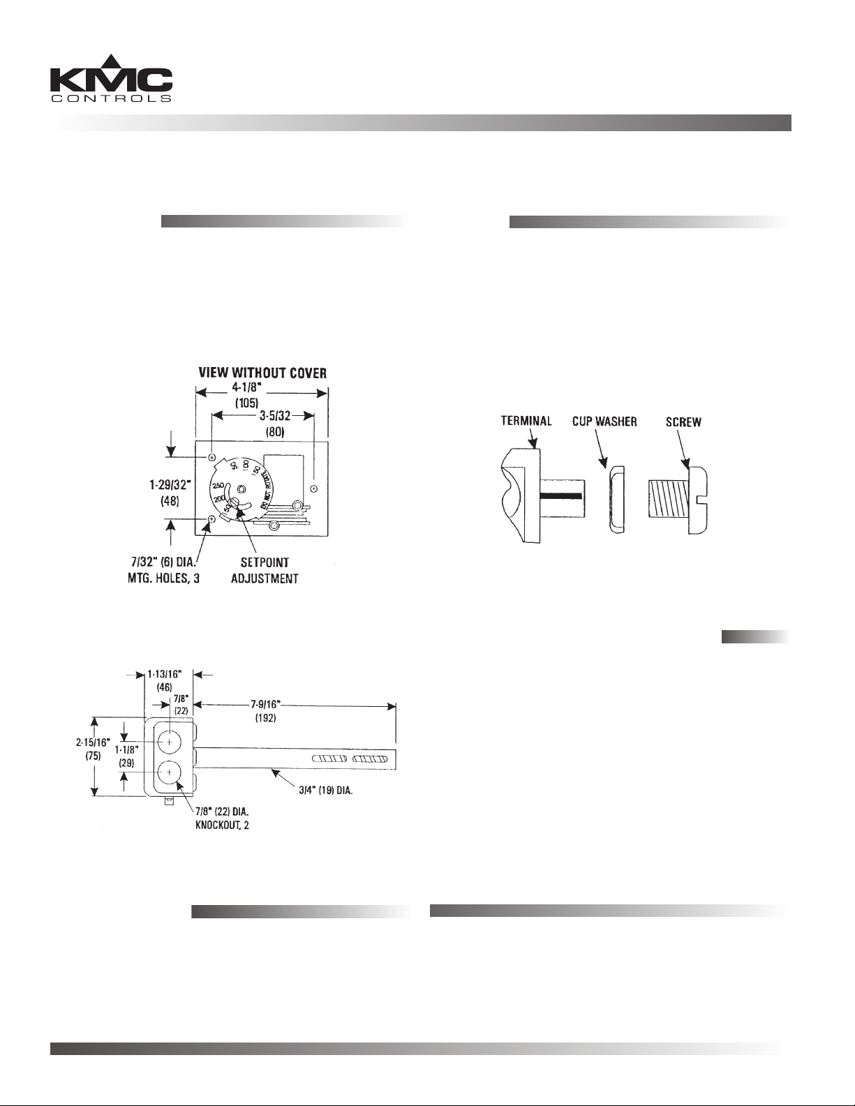
Illustration 1—Setpoint Adjustment and Dimensions
Wiring
1. Thread wiring for the low-voltage or line-voltage
circuit through the two 7/8" knockouts.
NOTE: If more than one CTE-6001 is connected to
the same load, connect them in series.
2. Connect the front terminals. Orient the cup
washer so the at surface is against the terminal.
(See Illustration 3.)
Illustration 3—Terminal (Exploded View)
Illustration 2—Side Dimensions
Maintenance
Periodically inspect the element for dirt/dust buildup. Each component is designed for dependable,
long term reliability and performance. Careful
installation will also ensure long term reliability and
performance.
Adjustments and Calibration
The CTE-6001 is shipped with a preset “cut-out”
temperature of 135° F (57° C). The temperature
setpoint is eld adjustable in a range of 100 to 250° F
(38 to 121° C).
To set “cut-out” temperature:
1. Loosen the screw in the setpoint adjustment lever.
(See Illustration 1.)
2. Slide the LEVER to the desired temperature.
NOTE: Do NOT rotate the DIAL.
3. Retighten the screw in the lever.
KMC Controls, Inc.
19476 Industrial Drive
New Paris, IN 46553
574.831.5250
www.kmccontrols.com; info@kmccontrols.com
BAC-1xx36 Series (3 Relays, 6 Analog Outputs) 1 Installation Guide
© 2009 KMC Controls, Inc. 717-019-25A
 Loading...