

Page 1
Electronic Room Thermostats
CTE–5101, 5102, 5103, 5104, 5105
Installation Guide
Required Tools
• digital voltmeter
• small phillips & flat-blade screwdrivers
• pliers
• 1/16" hex wrench
• key hole saw
Mounting
CTE–5100 series thermostats may be mounted horizontally or vertically to a standard 2" x 4" (51 x 102)
handy box using a HMO-5024/26 or 5030/5031 backplate, or directly to a hollow wall using drywall bracket
HMO-5023. Mount thermostats on walls unaffected by sunlight or drafts to ensure accurate average
temperature sensing. All CTE–5100 series thermostats require a scale plate and a cover which must be
ordered separately.
Electrical Box Mounting
1. Install, but DO NOT TIGHTEN, the HMO-5024/26 or 5030/5031
backplate to a handy box using the two 6-32 screws (included).
2. Adjust and level the backplate using the slotted mounting hole.
3. Tighten the two mounting screws.
4. Pull all thermostat wires and cable through the backplate and
decorative trim plate opening (included with HMO-5024/5026 or
5030/5031). Be careful not to damage the trim plate while wiring.
5. Connect the thermostat’s wires according to it’s particular
application. Refer to project drawing or the wiring chart.
6. Position the trim plate between the backplate and the thermostat
(cover removed).
7. Align the mounting holes and secure the assembly with the two
6-32 x 2" self-tapping screws (included).
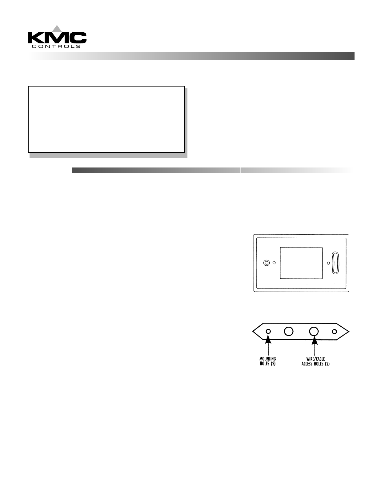
Hollow Wall Mounting
Thermostats may be mounted on a hollow wall up to 5/8" thick using the HMO–5023 Drywall Mounting Kit.
1. Using the template, cut a 1–1/2" x 2–11/16" opening in the drywall.
2. Loosely mount the HMO–5023 bracket to the thermostat (cover removed) using the two 6-32 x 2" screws.
HMO-5024/26 or 5030/5031
Back Plate
HMO–5023 Drywall Mounting Kit
3. Pull all thermostat wires or cable through the bracket’s ’wiring/cable access hole.
4. Connect the thermostat wires according to it’s particular application. Refer to the project drawing or the
wiring chart.
5. Insert bracket diagonally, through the wall opening, center and tighten screws.
Page 2
Mounting Continued
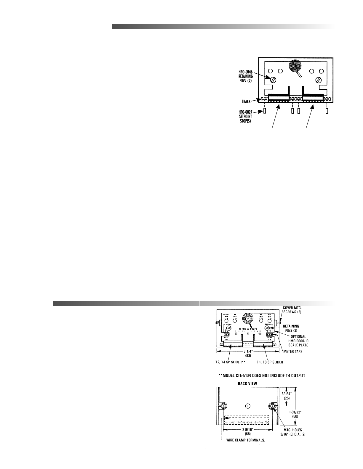
Setpoint Stops
Setpoints can be locked, or limited, using setpoint stops. Each HFO–0027
Setpoint Stop Strip (accessory sold separately) contains four stops.
1. Break a stop from the strip by gently folding on the seam with pliers.
2. Insert a stop into the slider track on one or both sides of the slider.
3. Repeat for second slider.
Scale Plates (required)
1. Install scale plate under the setpoint indicators.
2. Align mounting holes.
3. Insert the two retaining pins (HPO–0046, supplied) into the holes.
4. Twist pins 1/4 turn to firmly seat.
Covers
A symbol-coded label strip is included with the window style covers for
setpoint indication.
1. Remove the window by applying light pressure on its underside and
flexing upward.
2. Peel-off correct identity label from the strip of labels provided.
3. Position the label on the covers’ recessed area.
4. Snap window back in place.
5. Slide cover onto base.
6. Locate the set screw on each of the thermostats short sides.
7. Using a 1/16" hex/key wrench, turn set screws outward CCW until the
cover is secure. Turn set screws CW to remove cover.
Removeable thumb adjusters. See NOTE
Setpoint S tops
NOTE: When using a blank cover, remove the finger pads on the setpoint sliders. Hold the slider in
place, insert a small flatblade screwdriver into the slot in the metal slider. Twist the screwdriver
slightly to pop the pad off.
Wiring
Refer to the project plans, as built drawings or table
on the oposite pages for more information.
Page 3

Adjustments and Calibration
Thermal calibration is not required . Minimum and maximum control points can be calibrated before or
after the thermostat has been installed.
Adjusting the thermostat:
1. Using 1/16" hex/key, turn the setscrews on each side of the unit clockwise until the cover loosens.
2. Verify 16 VDC between the “+” and “–” terminals.
3. Remove set point slider stops (HFO-0027) if necessary.
4. Measure “T (?)” to “–” for output voltage. See table (below) to determine correct terminal.
5. Maximum limits MUST be greater than minimum limits. If in doubt, turn Max. limit fully clockwise
(increase) before proceeding.
NOTE: Dials rotate approximately 200° (8:00-4:00). DO NOT force dial beyond stop.
6. Connect voltmeter to to the meter taps (Using HSO-5001):
a. The two holes on the right are for the min. and max.
b. Measure actual flow in left holes. Thermostat must be wired to controller for this option.
7. Always adjust the minimum first. Adjust set point to request minimum flow using the minimum dial:**
DA Cooling; Set point > Room Temp.
RA heating; Set point < Room Temp.
8. Adjust set point to request maximum flow using the max. dial:**
RA Heating; Set point > Room Temp.
DA Cooling; Set point < Room Temp.
** Note: Limits may be set at the CSP or the thermostat. If setting min/max limits at the thermostat,
CSP’s Min. dial must be turned fully CCW to “0” AND the Max. dial must be turned fully
CW to “100”. This ensures that the CSP will not effect the limits.
Thermostat
Terminal
V1 X X X Velocity input for read-out
T3 X X X Upper set-point output w/o limits
R1 X X X T1 override connect to "–" if unused
T1 X X X Upper set-point output w/limits
+ X X X X 16 VDC power supply input
12V X X X X 12 VDC power output
A X X X X Temperature averaging input
5101 5102 5103/ 5105 5104 Description
– X X X X Ground reference
T2 X X X Lower set-point output w/limits*
R2 X X X T2 override, connect to "–" if unused.*
*T4 X X Lower sett-point out w/o limits
V2 X X Velo city input fo r read-out
* Except 5104; T2 lower setpoint output is w/o limits. R2 is auxiliary limit trigger, voltage above 1
VDC @ R2 indexes T1 to the auxiliary flow limit
Page 4

Maintenance
No routine maintenance is required. Each component is designed for dependable, long term reliability and
performance. Careful installation will also ensure long term reliability and performance.
KMC Controls
P.O. Box 497
19476 Industrial Drive
New Paris, IN 46553
U.S.A.
TEL: 574.831.5250
FAX: 574.831.5252
E-mail: info@kmccontrols.com
877-019-01A
 Loading...