

Page 1
Mounting
Electronic Room Thermostats
CTE-5100 Series
Installation Guide
General
CTE-5100 series thermostats require a scale plate
assembly and a cover, which must be ordered
separately. To ensure accurate temperature sensing,
mount thermostats on interior walls and away from
heat sources, sunlight, windows, air vents, and air
circulation obstructions (e.g., curtains and furniture).
These thermostats may be mounted horizontally or
vertically to a standard 2 x 4" (51 x 102 mm) handy
box using a HMO-5024/5026/5030/5031 backplate or
directly to a hollow wall using an HMO-5023 kit.
Electrical Box Mounting
1. Install, but DO NOT TIGHTEN, the HMO-
5024/5026/5030/5031 backplate to a handy box
using the two 6-32 screws (included).
2. Adjust and level the backplate using the sloed
mounting hole.
3. Tighten the two mounting screws.
4. Pull all thermostat wires and cable through the
backplate and decorative trim plate opening (of
the HMO-5024/5026/5030/5031). Be careful not to
damage the trim plate while wiring.
5. Connect the thermostat’s wires according to its
particular application. See the Connections and
Wiring section.
6. Position the trim plate between the backplate and
the thermostat (with the cover removed).
7. Align the mounting holes and secure the
assembly with the two 6-32 x 2" self-tapping
screws (included).
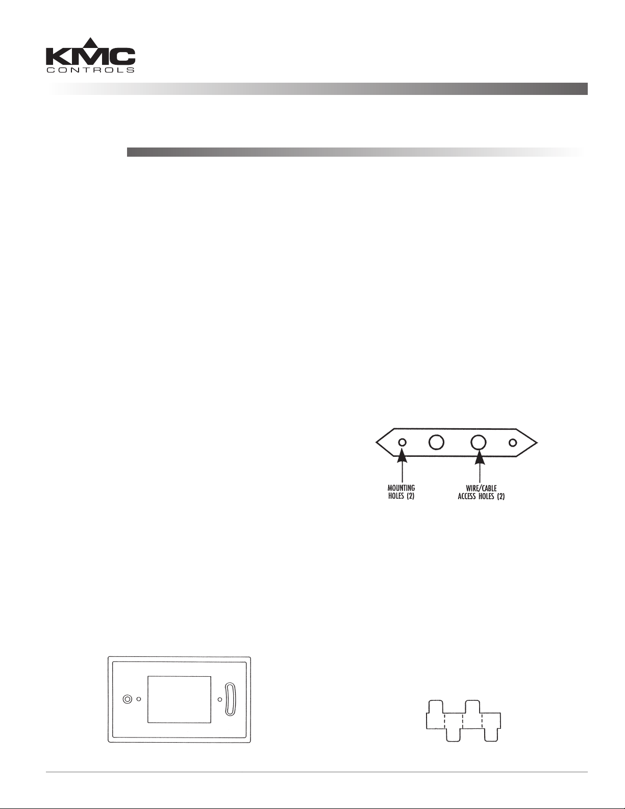
Hollow Wall Mounting
Thermostats may be mounted on a hollow wall up to
5/8" thick using the HMO-5023 hollow wall mounting kit.
1. Using the template, cut a 1-1/2 x 2-11/16" opening
in the drywall.
2. Loosely mount the HMO-5023 bracket to the
thermostat (with cover removed) using the two
6-32 x 2" screws.
3. Pull all thermostat wires or cable through the
bracket’s wiring/cable access hole(s).
4. Connect the thermostat wires according to its
particular application. See the Connections and
Wiring section.
5. Insert bracket diagonally, through the wall
opening, and then center and tighten the screws.
HMO-5023 Hollow Wall Mounting Kit (Screws Not Shown)
Setpoint Stops
Optional setpoint stops can be used to lock or limit
the setpoint range. Each HFO-0027 setpoint stop
strip (accessory sold separately) contains four stops.
1. Break a stop from the strip by gently folding on
the seam with pliers.
2. Insert a stop into the slider track on one or both
sides of the slider.
3. Repeat for second slider.
HMO-5024/5026/5030/5031 Back Plate
CTE-5100 Series 1 Installation Guide
HFO-0027 Setpoint Stop Strip
Page 2
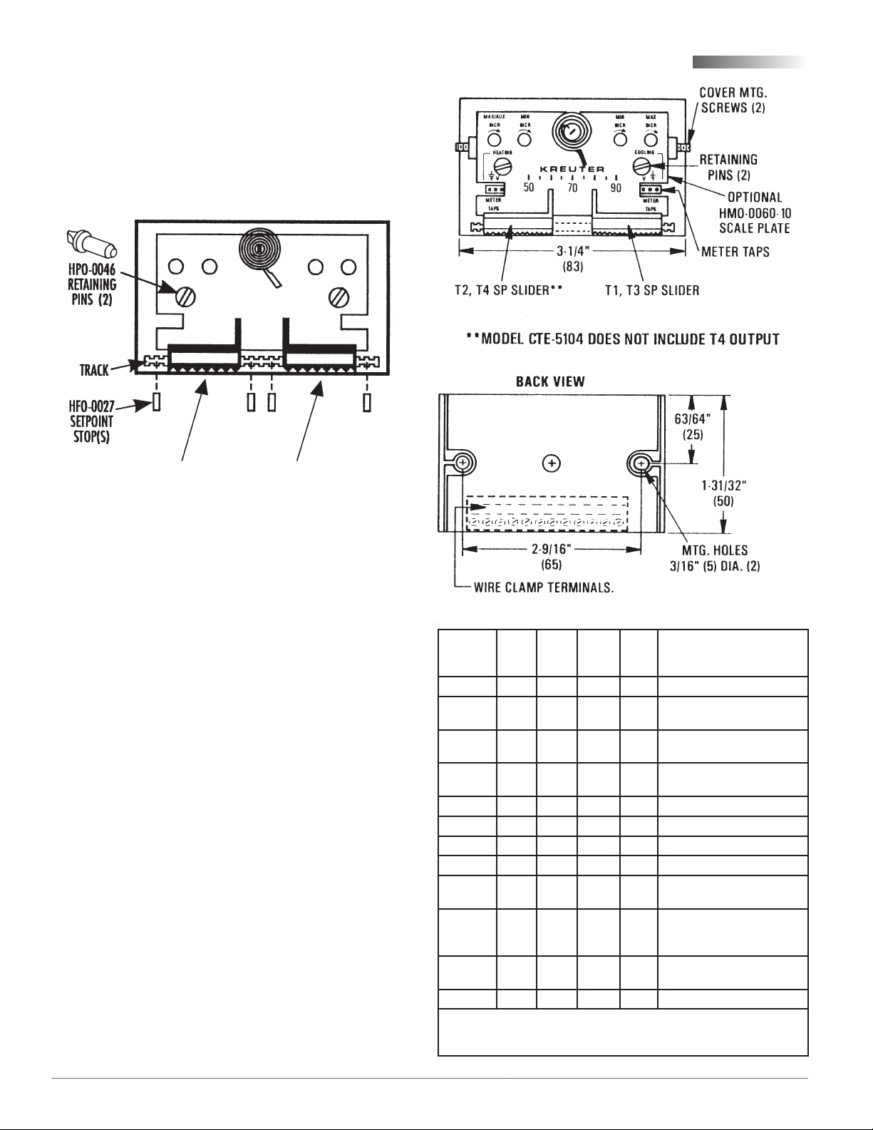
Scale Plate
1. Install scale plate under the setpoint indicators.
2. Align mounting holes.
3. Insert the two (supplied) HPO-0046 retaining pins
into the holes.
4. Twist pins 1/4 turn to rmly seat.
REMOVEABLE SETPOINT ADJUSTER PADS (SEE NOTE)
Retaining Pins, Setpoint Stops, and Setpoint Sliders
Connections and Wiring
(Depth
with
cover,
not
shown)
1-7/8"
(47 mm)
Cover
NOTE: When using a blank cover (without a
window), remove the nger pads on the
setpoint sliders. Hold the slider in place,
insert a small at blade screwdriver into
the slot in the metal slider. Twist the
screwdriver slightly to pop the pad o.
With the window style covers, a symbol-coded label
strip is included to apply to the covers for setpoint
indication.
1. Remove the window from the cover by applying
light pressure on its underside and exing
upward.
2. Peel o correct identity label from the strip of
labels provided.
3. Position the label on the cover’s recessed area.
4. Snap window back in place.
5. Slide cover onto base.
6. Locate the setscrew on each of the thermostats
short sides.
7. Using a 1/16" hex wrench, turn setscrews outward
CCW until the cover is secure. (Turn setscrews
CW to remove cover.)
CTE5102
CTE-
5103/
5105
CTE5104
Description
Upper setpoint output
without limits
T1 override,
connect to “–” if unused
Upper setpoint output
with limits
Lower setpoint output
with limits*
T2 override (voltage applied
to R2 subtracts from T2),
connect to “–” if unused*
Lower setpoint out
without limits
Terminal
V1 X X X Velocity input for read-out
T3 X X X
R1 X X X
T1 X X X
12V X X X X 12 VDC power output
T2* X X X
R2* X X X
T4 X X
V2 X X Velocity input for read-out
*Except CTE-5104, in which T2 lower setpoint output is without limits.
Also CTE-5104’s R2 is auxiliary limit trigger, in which voltage above 1
CTE5101
+ X X X X 16 VDC power supply input
A X X X X Temp. averaging input
– X X X X Ground reference
VDC to R2 indexes T1 to the auxiliary ow limit.
CTE-5100 Series 2 Installation Guide
Page 3

CTE-5100 Series 3 Installation Guide
Page 4

Adjustments and Calibration
More Information
Thermal calibration is not required. Minimum and
maximum control points can be calibrated before or
aer the thermostat has been installed.
1. Turn setscrews CW and remove cover.
2. Verify 16 VDC between the “+” and “–” terminals.
3. Remove setpoint slider stops (HFO-0027) if
necessary.
4. Measure “Tx” to “–” for output voltage. (See the
table on page 2 and the graphs on pages 3 and 4
to determine the correct T terminal.)
5. Maximum limits MUST be greater than
minimum limits. If in doubt, turn maximum limit
fully clockwise (increase) before proceeding.
NOTE: Dials rotate approximately 200° (8:00–4:00).
DO NOT force dial beyond stop.
6. Connect a voltmeter to the meter taps (using an
HSO-5001):
a. The two holes on the right are for the
minimum and maximum.
b. Measure actual ow in le holes. The
thermostat must be wired to a controller for
this option.
7. Always adjust the minimum rst. Adjust setpoint
to request minimum ow using the minimum
dial:
• DA Cooling; Set point > Room Temp.
• RA heating; Set point < Room Temp.
NOTE : Limits may be set at the CSP series
controller or the thermostat. If seing min./
max. limits at the thermostat, the CSP’s
Min. dial must be turned fully CCW to “0”
AND the Max. dial must be turned fully
CW to “100.” This ensures that the CSP will
not aect the limits.
8. Adjust the setpoint to request maximum ow
using the Max. dial:
• RA Heating; Set point > Room Temp.
• DA Cooling; Set point < Room Temp.
9. Reinstall the cover and turn setscrews CCW until
the cover is secure.
For more wiring and calibration details as well as
sample applications, see the CSP-5001/5002 Applica-
tions Guide.
For specications, accessories list, and other information, see the CTE-5100 Series Data Sheet.
Important Notices
The material in this document is for information
purposes only. The contents and the product it
describes are subject to change without notice.
KMC Controls, Inc. makes no representations or
warranties with respect to this document. In no event
shall KMC Controls, Inc. be liable for any damages,
direct or incidental, arising out of or related to the
use of this document.
Maintenance
Remove dust as necessary from the holes in the
cover. Clean the window with a so, damp cloth and
mild soap if needed.
CTE-5100 Series 4 Installation Guide
© 2012 KMC Controls, Inc. 877-019-01C
KMC Controls, Inc.
19476 Industrial Drive
New Paris, IN 46553
574.831.5250
www.kmccontrols.com
info@kmccontrols.com
 Loading...