

Page 1
Low Limit Controllers, DPDT
Installation Guide
CTE-3016/3017/3026/3027
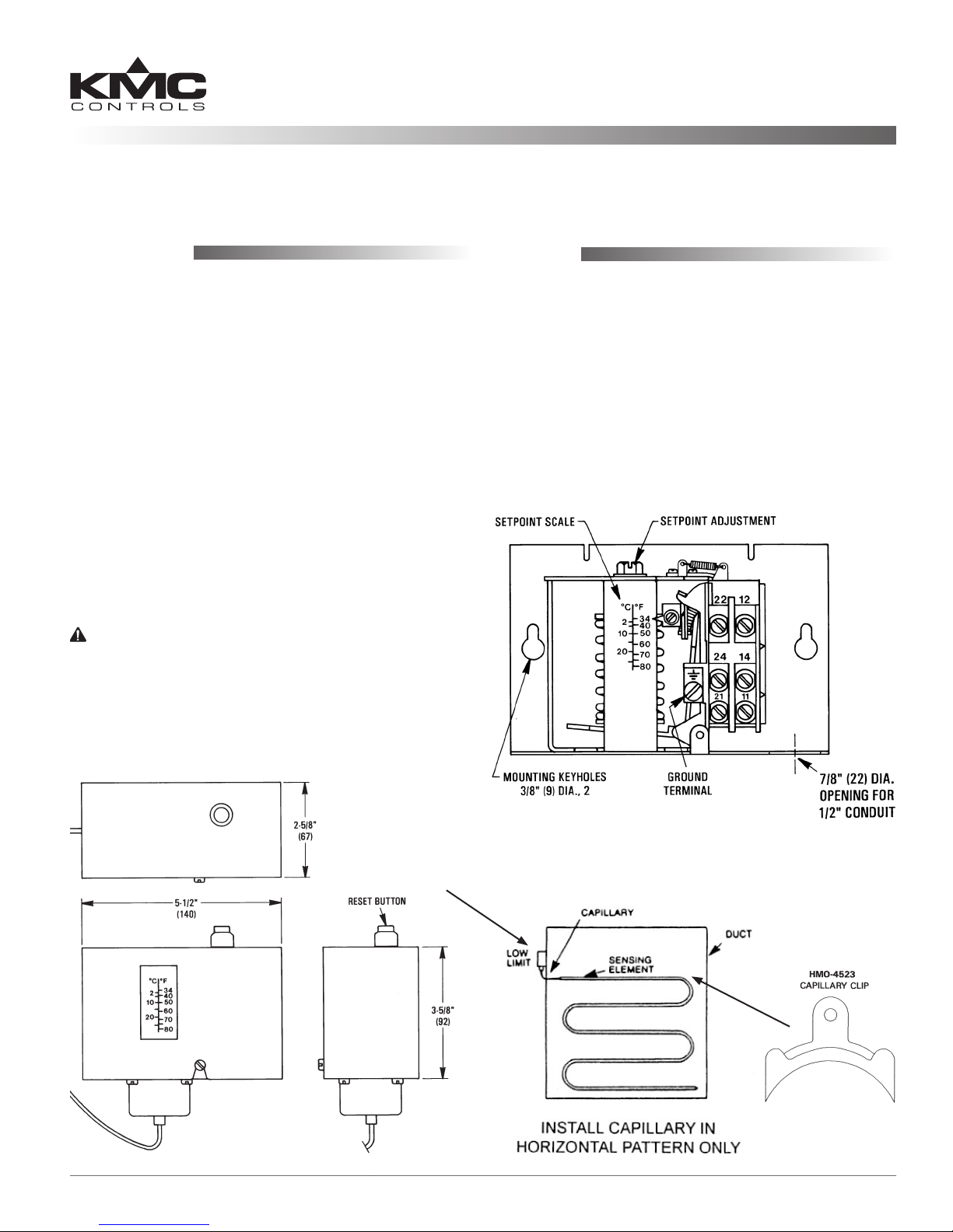
Mounting
The controller can be mounted in any position,
but avoid locations subject to excessive vibration.
For manual reset models, position the controller to
permit convenient access to the reset buon.
1. Loosen the front screw and remove the cover.
2. Using the two 3/8" mounting keyholes, mount
the case ush against the duct work or any at
surface.
3. Install the sensing capillary in a horizontal
serpentine fashion across the downstream side of
a water coil.
4. Using the included HMO-4523 capillary clips,
support the sensing capillary at sucient points
to prevent damage from vibration and/or air
movement.
CAUTION
Do not kink or apply excessive force to the capillary
element.
5. Make the appropriate connections to the terminal
blocks. (See the Wiring section.)
Wiring
An opening for installing a connector for 1/2" conduit
is provided in the boom of the case.
All wiring should comply with national and local
electrical codes. Using 14 AWG solid copper wire is
recommended.
Strip wire ends 3/8", insert the wire ends under
the cup washers on the switch block, and securely
retighten terminal screws. Wire terminals according
to the Actuation and Reset section on the next page.
CTE-3016/3017/3026/3027 1 Installation Guide
CTE-3017 Shown
Page 2
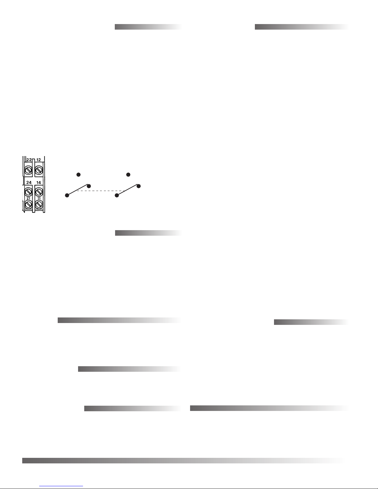
Actuation and Reset
Specifications
Terminals 11 and 21 are “common” terminals, 14
and 24 are Normally Closed (above setpoint), and
12 and 22 are Normally Open (see the diagram
below). When the sensed temperature falls below
setpoint, connections “11–14” and “21–24” open and
connections “11–12” and “21–22” close. The switch
latches in this position until the sensed temperature
rises 5° F (3° C) above setpoint and the controller is
reset either (depending on the model) automatically
or manually by depressing the reset buon located in
the top of the controller case.
The controller cannot be manually reset until the
sensed temperature is at least 5° F (3° C) above the
setpoint.
22 (NO)
24 (NC)
21
(Common)
(Connections Shown in Above-Setpoint, NC, Unactuated Position)
11
(Common)
12 (NO, Closes
on Low Temp.)
14 (NC, Opens
on Low Temp.)
Setpoint Adjustment
The setpoint is the temperature at which contacts
“11–14” and “21–24” open as the unit senses a fall in
temperature. To adjust the setpoint:
• Turn the range adjustment screw CW to decrease
the setpoint.
• Turn the range adjustment screw CCW to
increase the setpoint.
Range 34° to 70° F (1.1° to 21° C)
Dierential 4.5° F xed (2.5° C)
Switch Action DPDT
Element
Electrical Ratings
Inductive 14 FLA (Full Load Amperes)
84 LRA (Locked Rotor
3/4 HP @ 120 VAC, 2 HP @ 240
Pilot Duty 720 VA max. @ 120 to 600 VAC,
Approvals CUL US Listed, CE Compliant,
Weight 1.2 lbs. (0.54 kg)
Materials Plated steel case, plastic cover
Mounting Surface mount with capillary
Temperature Limits
Operating –60 to 160° F (–51 to 71° C)
Shipping –60 to 160° F (–51 to 71° C)
NOTE: See the CTE-3016/3017/3026/3027 Data
3/32" (2.4 mm) diameter, 6-foot
(183 cm) or 20-foot (607 cm)
length, vapor-lled, tin-plated
copper capillary, maximum
temperature 300° F (149° C)
@ 120 VAC, 12 FLA @ 240 VAC
Amperes) @ 120 VAC, 72 LRA
@ 240 VAC
VAC
144 VA max. @ 24 VAC
RoHs compliant
installed in horizontal serpentine paern
Sheet (717-035-21) for more information.
Testing
A manual test lever located under the cover (below
and to the le of the controller spring) allows the
unit to be manually actuated during system tests.
Accessories
HMO-4523 Capillary Clip (3 or 5 provided,
depending on length)
Maintenance
No routine maintenance is required. Each component is designed for dependable, long-term reliability, and performance. Careful installation will also
ensure long-term reliability and performance.
© 2010 KMC Controls, Inc. 717-019-21B
CTE-3016/3017/3026/3027 2 Installation Guide
Important Notices
The material in this document is for information
purposes only. The contents and the product it
describes are subject to change without notice. KMC
Controls, Inc. makes no representations or warranties with respect to this document. In no event shall
KMC Controls, Inc. be liable for any damages, direct
or incidental, arising out of or related to the use of
this document.
KMC Controls, Inc.
19476 Industrial Drive
New Paris, IN 46553
574.831.5250
www.kmccontrols.com; info@kmccontrols.com
 Loading...