

Page 1
Dual Temperature Room Thermostat
Installation Guide
Required Tools
• digital voltmeter
• small phillips screwdriver
• small flatblade screwdriver
• keyhole saw
Mounting
Standard:
• The base unit’s mounting slots are designed to align with the
holes in a standard 2" x 4" (51x102) handy conduit box.
• Use a 2" (51) deep box if using conduit.
CTE –1005, 1008, 1105, 1108
• Normal screw and anchor systems may be used on solid
walls.
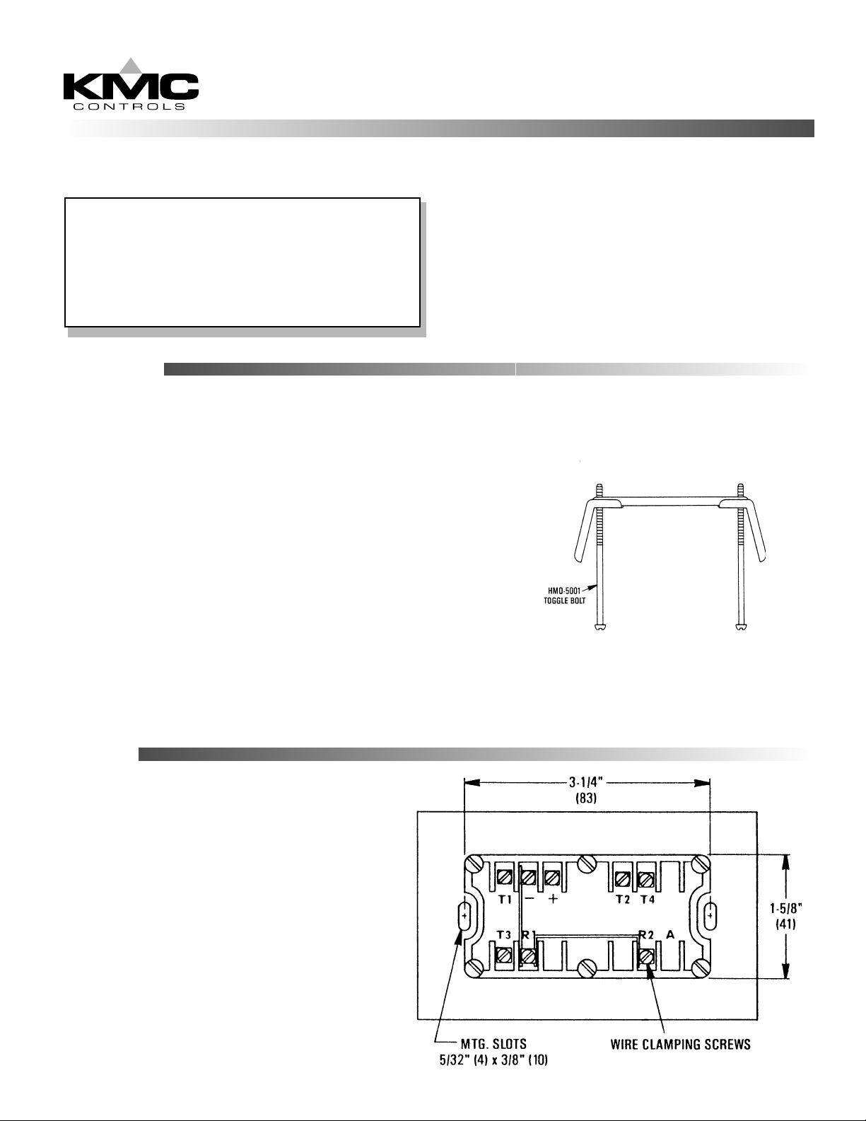
Hollow wall:
1. Cut a 3-3/4" x 1-3/4" rectangular opening in the wall.
(Check if unit is horizontal or vertical before cutting)
2. Make all necessary connections
3. Insert Toggle Bolt Assembly (HMO-5001, ordered separately)
through the wall and tighten.
Care should be taken not to bend or flex the base of the
thermostat.
Wiring
Typically, T1 and T3 are used for cooling and T2
and T4 are used for heating. Refer to the wiring
diagram.
Page 2
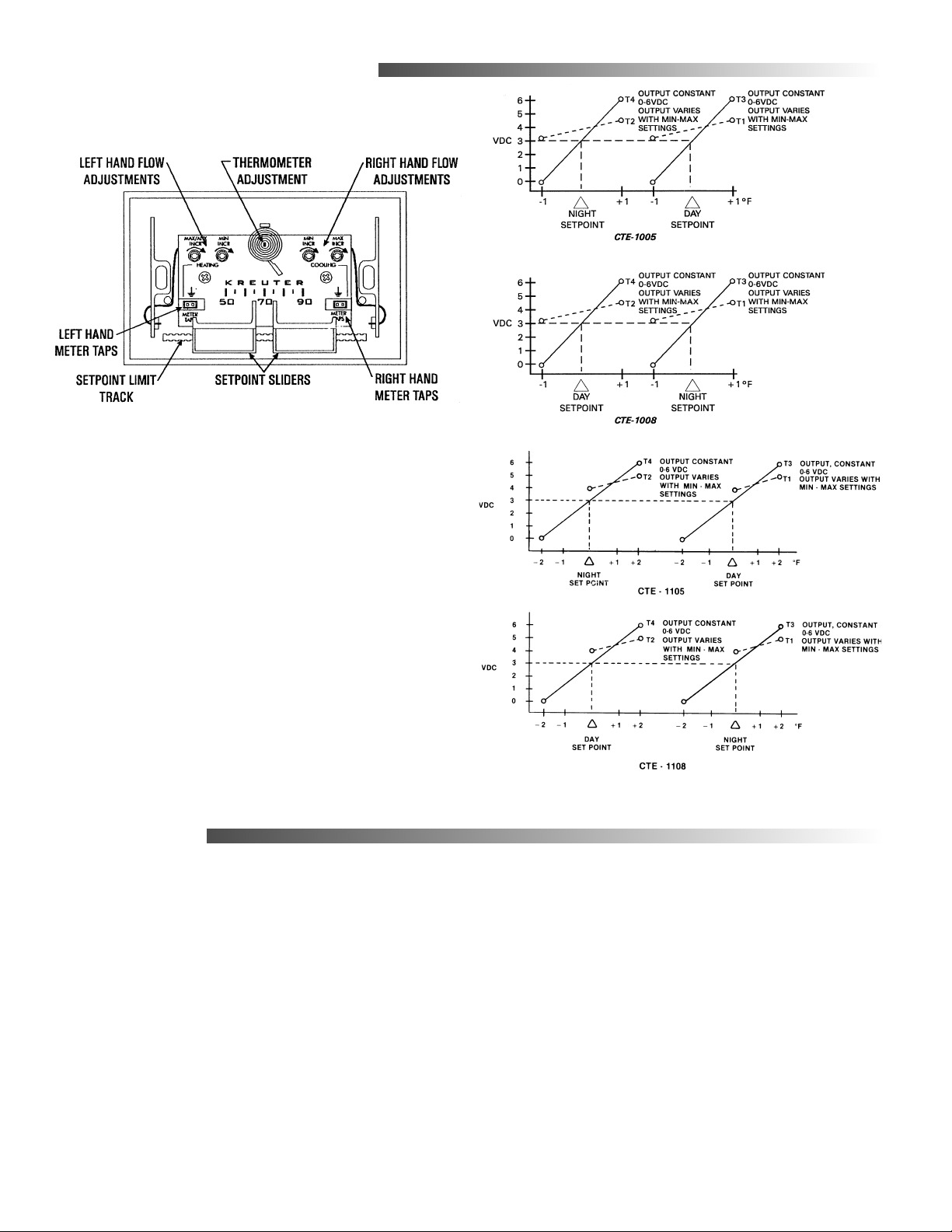
Adjustments and Calibration
Upon receipt, no thermal calibration should be
required.
Flow control points can be calibrated before or after
installation.
1. Verify 9.1 VDC between (+) and (-) terminals.
Refer to wiring diagram.
2. Measure T1 output voltage.
3. Refer to the graphs (right) to make adjustments.
4. Always adjust the minimum flow first.
a. DA Cooling; Set point > Room Temp.
b. RA Heating; Set point < Room Temp.
5. Always adjust maximum limits to a value higher
than the minimum limits. If in doubt, turn Max.
limit fully clockwise (increase) before
proceeding.
a. DA Cooling; Set point < Room Temp.
b. RA Heating; Set point > Room Temp.
Maintenance
No routine maintenance is required. Each
component is designed for dependable, long term
reliability and performance. Careful installation will
also ensure long term reliability and performance.
KMC Controls
P.O. Box 497
19476 Industrial Drive
New Paris, IN 46553
U.S.A.
TEL: 574.831.5250
FAX: 574.831.5252
E-mail: info@kmccontrols.com
818-019-01A
 Loading...