

Page 1
2/3-Pipe, 2-Temperature, Pneumatic Thermostats, w/ Indexing
Installation Guide
Mounting
Mount the thermostats on an inside wall away from
direct sunlight, heat sources, windows, air vents, and
air circulation obstructions (curtains, furniture, etc.).
Choose the location best suited for measuring the
average room temperature. Units may be mounted
horizontally or vertically to either a 2" x 4" electrical
box or a hollow wall.
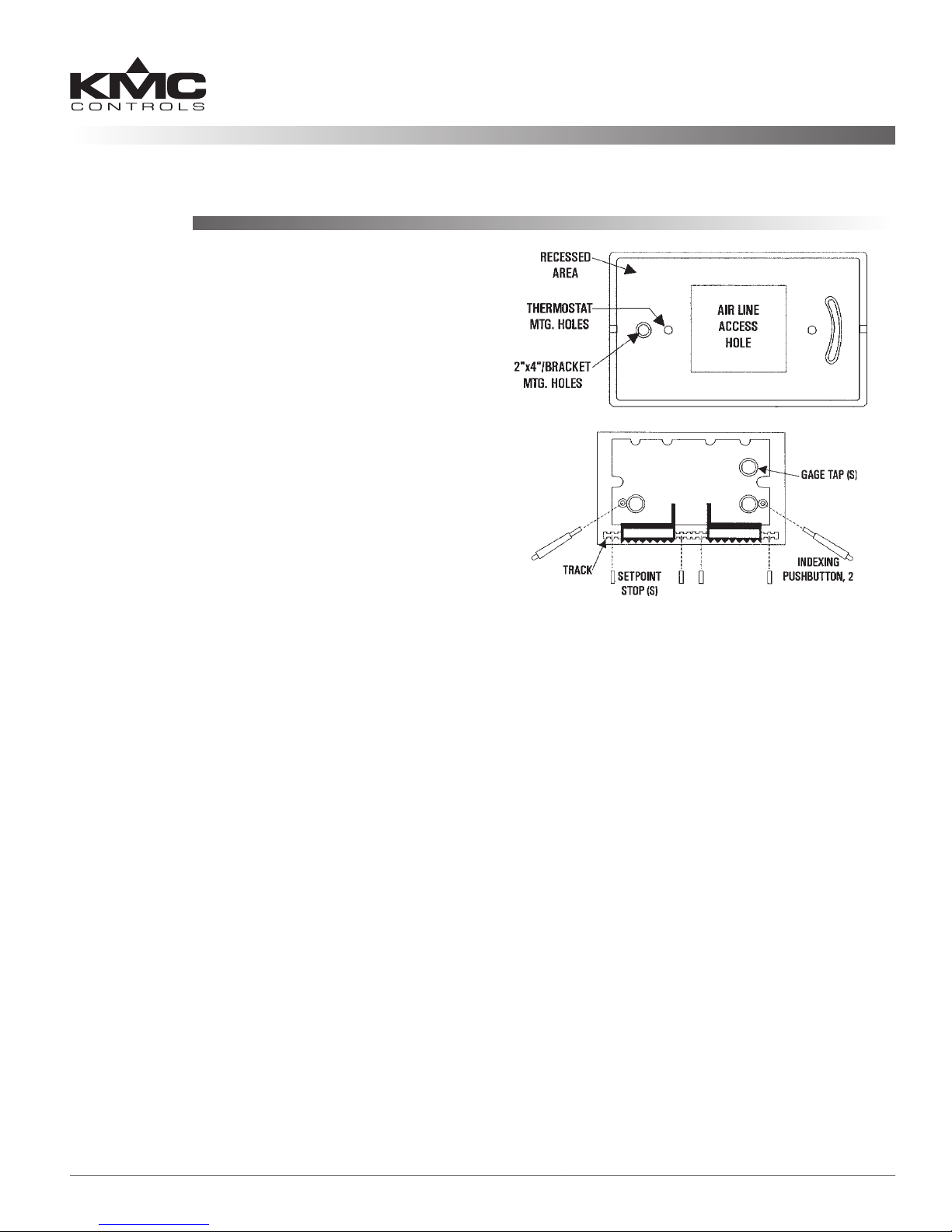
Electrical Box Mounting
1. Aach the HMO-5024/5026/5030/5031 backplate
to the box with the two 6-32 screws supplied.
2. Level the box using the slot in the backplate.
CTC-1653/1654
3. Fit the aluminum plate into the recess.
4. Pass the 3/32" ID tubing through access hole.
5. Make connections. See the Connections section.
6. Mount the thermostat to backplate with two 6-20
x 2" screws supplied with thermostat.
Hollow Wall Mounting
Thermostats may be directly mounted on walls up to
5/8" with the HMO-5023 kit.
1. Using the template, printed on the package, make
a 2-11/16" x 1-1/2" cutout.
2. Loosely mount the bracket to the thermostat with
two 6-32 x 2" screws supplied.
3. Make connections. See the Connections section.
4. Insert the bracket diagonally through the wall.
5. Center the thermostat and tighten screws.
Scale Plate
Adjustments must be made with the scale plate
removed. Complete adjustments before installing the
scale plate.
1. Remove all gauge tap rubber cap(s).
2. Slide plate under the setpoint indicator(s).
3 Insert retaining pins (two supplied), twisting to
lock into place.
4. Replace gauge tap cap(s).
Setpoint Options
• If setpoint indicators are not needed, simply snip
o the indicator(s) with wire cuers.
• Limit or lock the range of the setpoint(s) by
installing setpoint stops (HFO-0027) in the slider
track.
Cover Installation
1. Check that the unit is mounted securely and all
gauge tap cap(s) or accessories are installed.
2. Place longer, tapered ends of push-buon into the
two holes in the thermostat.
3. Align cover over push buons, so that short ends
protrude.
4. Slide the cover over the base.
5. Using a 1/16" hex wrench, turn both cover
mounting screws on the thermostat base CCW
(outward) until cover is secured.
NOTE: If used, blank covers require the removal of
the setpoint thumb adjusters. Insert a small
screwdriver in the slot between the thumb
adjuster and the cam and pry apart. Discard
the adjuster.
CTC-1653/1654 1 Installation Guide
Page 2
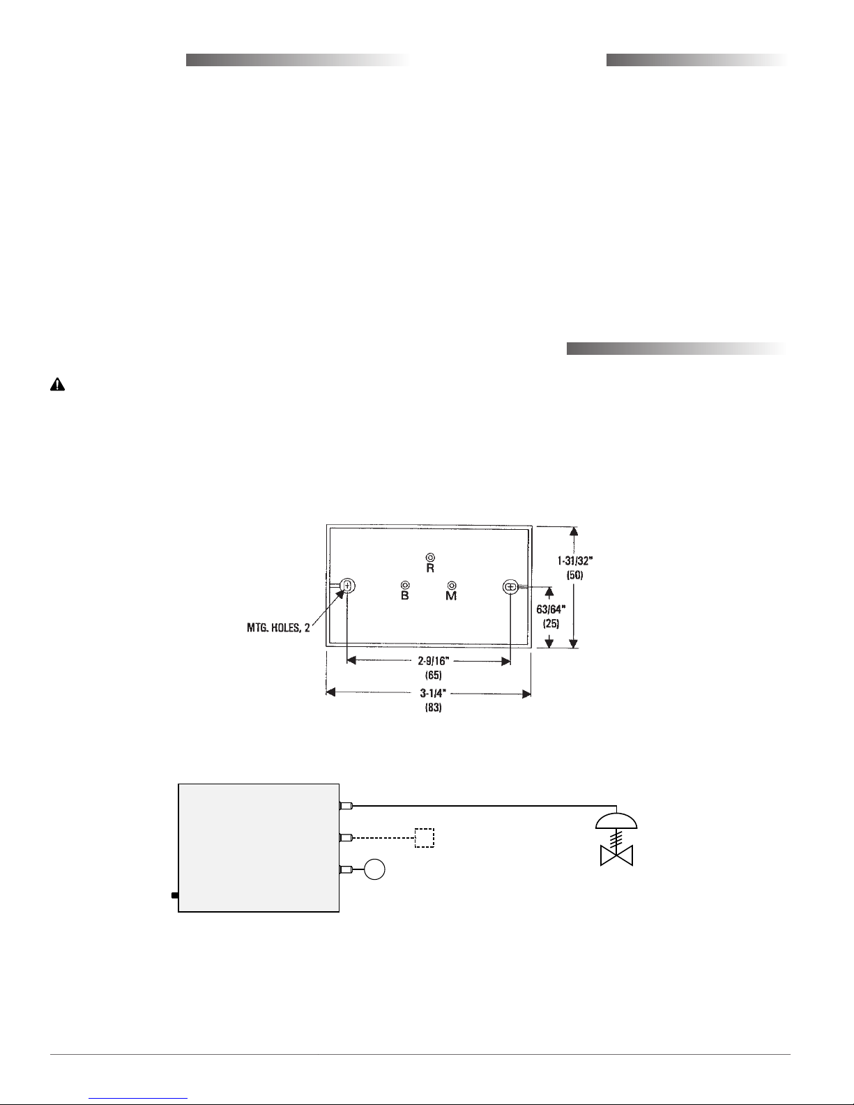
Connections
Remote Indexing
The CTC-1653 and CTC-1654 use 3/32" ID tubing
(HFO-0028) for all connections.
1. Connect Main Air to Port M.
2. Connect Branch Air to Port B.
For a three-pipe application continue by:
3. Clipping o Port R’s tip.
4. Connecting Port R to the appropriate air line.
NOTE: Pressure at Port R will be 16 psi with 16 psi
main air pressure, and 25 psi with 25 psi
main air pressure. When pressure is at 25
psi, depressing the right (or top) indexing
buon will drop the R port pressure to 0
psi. See also the Remote Indexing section.
CAUTION
Pneumatic devices must be supplied with clean, dry
control air. Any other medium (e.g., oil or moisture
contamination) will cause the device to fail.
Remote indexing is via dual main air supply pressure, and local indexing is by push-buon (HPO-
0045) control. Control of one temperature (right
indicator for horizontal, top for vertical) occurs when
the main air supply is 16 psi. The second temperature (le indicator for horizontal, boom for vertical)
is selected when the main pressure is 25 psi. When
25 psi is supplied, control may be changed to the 16
psi indicator by pressing right (or top) buon. If desired, control can be returned to the 25 psi indicator
by pressing the le (or boom) buon. When main
air supply is changed to 16 psi, control automatically
returns to the 16 psi indicator.
Maintenance
No routine maintenance is required. Each component is designed for dependable, long-term reliability, and performance. Careful installation will also
ensure long-term reliability and performance.
Output Signal: B
Secondary Output: R
Main Air: M
Local Indexing Button
CTC-1653/1654 2 Installation Guide
Optional
Secondary Device
(e.g., PE Switch)
M
Main Air
(Remote Indexing—
16 psi/day and 25 psi/night)
Controlled Device
(e.g., Valve)
Page 3

Adjustments and Calibration
Calibration
These thermostats are factory calibrated and normally do not require further calibration. If it is necessary
to change calibration:
1. Remove the cover and gauge-tap rubber caps.
2. Install a gauge on the gauge tap using 3/32" ID
tube.
3. Measure the ambient temperature with an
accurate thermometer.
4. Move the setpoint slider to the measured ambient
temperature.
5. Use a 1/16" hex wrench and turn the calibration
adjustment until the test gauge indicates the
desired pressure. (Clockwise rotation decreases
the output pressure.)
6. Replace the gauge tap rubber cap aer
calibrating.
7. Place the setpoint slider to the desired
temperature and replace the cover.
Throttling Range
Throling range is the temperature required to
change the thermostat output pressure from 3 to 15
psi. These thermostats are factory-set for a 3° F throttling range. The approximate throling range seing
is stamped on each lever in both °F and °C. If this
seing is changed, recheck calibration aerwards.
1. Remove the scale plate.
2. Slide the black “TR” adjuster to appropriate
value/ location.
NOTE: The hole in the “TR” adjuster ts a 1/16"
hex wrench. Gently rotate the adjuster
back and forth while sliding. Do not turn
excessively!
3. Rotate back to a “square” position aer
adjustment.
4. Replace the scale plate (see the Mounting section).
Accessories
Backplate kit (allows thermostat to be mounted to
2x4 handy box, includes 2 #6-32 screws and deco-
rative matching plate):
HMO-5024 Light almond w/ aluminum trim
HMO-5026 White w/ aluminum trim
HMO-5030 Light almond
HMO-5031 White
Thermostat scale plates (includes 2 each HPO-0046
scale plate pins):
HPO-0047-10 °F Horizontal scale plate
HPO-0048-10 °F Vertical scale plate
HPO-0049-11 °C Horizontal scale plate
HPO-0050-11 °C Vertical scale plate
Thermostat covers, with local indexing:
HPO-1521 Light almond ABS plastic
HPO-1522 White ABS plastic
HPO-1523 Brushed aluminum
HPO-1526 Painted light almond metal
NOTE: Other covers without the holes for local
indexing are also available from KMC if
desired. See the CTC-1600 Series ONLY
Accessories section in the Electronic and
Pneumatic Controls Condensed Catalog
(SP-071) for details.
Miscellaneous accessories:
HFO-0027 Setpoint stop strip, 4 stops per strip
HFO-0028 Tubing kit; 3/32” ID
HMO-5023 Mounting strap for mounting on
hollow walls, includes 2 #6-32 x
2" screws and “template” printed
on envelope
HPO-0044 Replacement cover screws
HPO-0045 Indexing push buon
HPO-0046 Replacement scale plate pins
HPO-0051 Replacement cover window for
thermostat (1 furnished with
each cover)
HPO-1320 Label strip, 3 labels per strip (for
day/night, summer/winter or
heating/cooling indication), 1
furnished with each cover
CTC-1653/1654 3 Installation Guide
© 2009 KMC Controls, Inc. 3 516-019-01A
KMC Controls, Inc.
19476 Industrial Drive
New Paris, IN 46553
574.831.5250
www.kmccontrols.com; info@kmccontrols.com
 Loading...