

Page 1
Mounting
1.563
(39.7)
Analog Differential-Pressure VAV Controller/Actuator
CSP-4702
Installation Guide
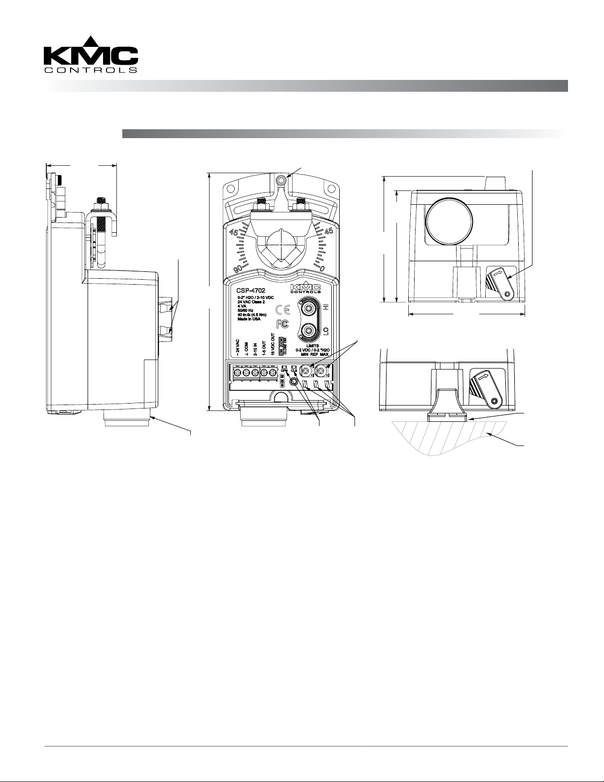
Gear
Adjustable Stop
Disengagement Lever
2.812
(71.4)
2.50
(63.5)
2.60
(66.0)
HMO-4002
Non-Rotation
Bracket
Mounting
Surface
∆
P Ports
Barbed
Connections
for 1/4" FR
Tubing
5.312
(134.9)
Removeable Conduit Fitting
with 1/2" NPS Threaded Hole
Open &
Close
LEDs
Min/Max
Flow
Setting
Pots
Min/Max
Flow Limit
Meter Taps
Illustration 1—Overview (Direct-Coupled Mounting)
NOTE: For VAV applications with the analog
CTE-5202 thermostat, see the CTE-5202
Applications Guide. For static pressure
3. Align the actuator and slide it onto the shaft.
approximately 5° may provide tight
damper shut-o.
controller applications, see the CSP-
4702 Static Pressure (Bypass) Control
Application Guide.
4. Leaving a small gap between the actuator and
mounting surface to prevent any binding, ngertighten the nuts on the V-bolt.
The CSP-4702 mounts directly to 1/4- to 5/8-inch (6 to
16 mm) round shafts or 1/4- to 7/16-inch (6 to 11 mm)
square shafts.
5. Insert the provided (HMO-4002) non-rotation
bracket into the slot at the base of the actuator
and secure the non-rotation bracket with two #8
1. Ensure the damper can move freely through its
or #10 self-tapping screws.
entire range of motion, and x any binding before
installing the actuator. Turn the damper blade to
its fully closed position.
2. Press (to the right) and hold the gear disengage-
ment lever (see Illustration 1), rotate the actuator
to the fully closed position, and release the lever.
NOTE: Depending on the damper-seal design,
backing the actuator o its stop
6. Evenly tighten the V-bolt nuts (30–35 in-lb.).
7. If desired, use a 7/64-inch hex key wrench to
loosen and position the end-stop screw.
NOTE: The two holes at the top of the actuator
are NOT for use in direct-coupled
applications. (They are for remote
mounting, such as with the optional HLO4001 Crank Arm Kit.)
CSP-4702 1 Installation Guide
Page 2
Wiring Connections
Air Pressure Connection
1. Loosen the screw on the conduit ing and lift up
to remove the ing.
2. Using a utility knife or drill, cut the red plug
to accept wiring or replace the plug with an
application-specic ing.
NOTE: The red plug (or similar ing) protects
internal components from debris, helping to
ensure long actuator life.
3. Thread wires through the plugged opening and
connect to the terminal block as shown.
4. Make the air pressure connections (see Air
Pressure Connection on page 2), set MIN/
MAX ow (see Min. and Max. Flow Limits on
page 3), and change the rotation direction (see
Rotation Direction on page 2) as needed.
5. Reinstall the conduit ing and tighten the screw.
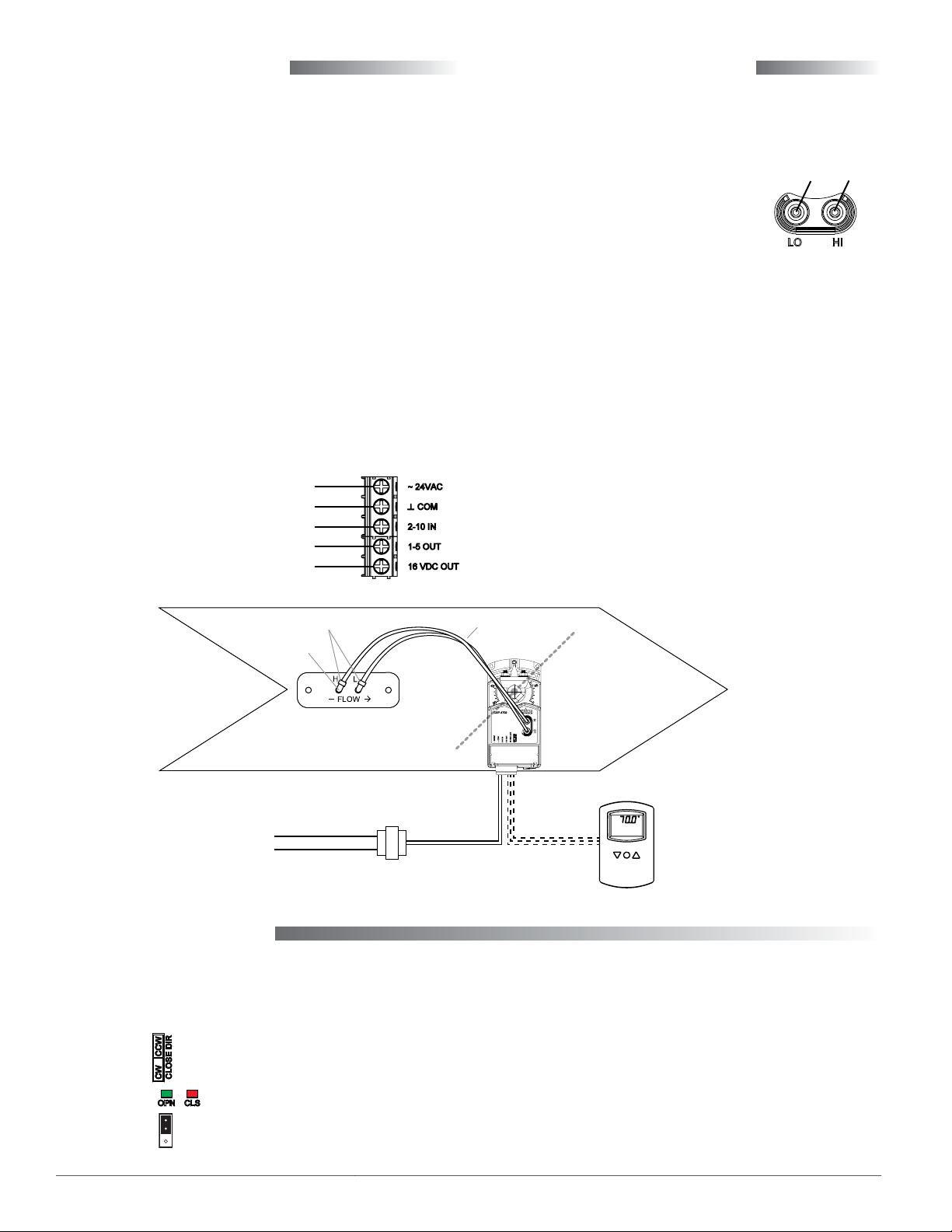
~24 VAC (Class 2 Only) Power
Common (Power, Input, Outputs)
2–10 VDC Thermostat Signal (Input)
1–5 VDC Air Pressure Signal (Output)
16 VDC Power to Thermostat (Output)
Connect the CSP-4702 to a dierential pressure ow
sensor with 1/4-inch OD x 0.040-inch wall FR instrument and control tubing:
1. Connect the “HI” port to the
To
“ L”
To
“H”
(high side) “H” of the sensor.
2. Connect the “LO” port to the
(low side) “L” of the sensor.
NOTE: For use as a static pressure controller, see
the CSP-4702 Static Pressure (Bypass)
Control Application Guide.
NOTE: For VAV applications, the SSS-1000 series
dierential pressure ow sensor must be
mounted with the arrow pointing in the
direction of the air ow. To connect to 1/4inch tubing from the CSP-4702, an SSS-100x
dierential pressure ow sensor requires
a 3/8" to 1/4" barb union adapter and 1"
of 3/8" OD x 0.062 “FR” tubing for both
connections (as shown in the illustration).
An SSS-101x sensor does not require the
3/8" tubing or adapter.
NOTE: All tubing should be free of kinks and
restrictions.
3/8" to 1/4" Union Adapters
3/8" Tubing
SSS-100x Sensor
Illustration 2—Connections
1/4-Inch Tubing
CSP-4702
Damper
24 VAC CTE-5202
(Used in VAV
applications but
not in static
SET
POINT
pressure bypass
applications)
Rotation Direction
The CSP-4702 is factory-set for counterclockwise to
close. To reverse the direction (with the conduit cover
removed), move the jumper to the CW position.
CCW = Jumper on Upper 2 Pins
Illustration 3—Rotation Indicators and Jumper
CSP-4702 2 Installation Guide
NOTE: For about 15 seconds after power is applied,
no rotation occurs and one or both of the
LEDs will ash. The Close LED illuminates
(solid red) when the actuator is closing. The
Open LED illuminates (solid green) when
opening. When the actuator reaches the end
of rotation or the mechanical stop, the LED
may stay illuminated a brief time if the
called for condition remains unsatised.
Page 3

Min. and Max. Flow Limits
NOTE: If desired, the min. and max. limits can be
set within the thermostat or the CSP-4702,
but
do not try to set the limits at BOTH
the controller and the thermostat (or
else the limits will not reect either the
controller’s or the thermostat’s limits).
Limits Set at the CSP-4702
To set the minimum and maximum ow limits at the
CSP-4702 (with thermostat supplying 2–10 VDC):
1. Ensure the thermostat output is 2–10 VDC. For
the CTE-5202 thermostat, see the CTE-5202
Applications Guide.
2. Loosen the screw on the conduit ing and lift up
to remove the ing.
3. Connect a voltmeter to the meter taps. The
middle pin (REF) is the common for the outer
(MIN and MAX) pins.
4. Adjust the MIN potentiometer for the desired
minimum voltage. The factory default is 0 VDC =
0" wc.
NOTE: 1 VDC = 1" wc. If, for example, the desired
minimum is 0.5" wc, set the voltage for 0.5
VDC.
5. Adjust the MA X potentiometer to the desired
maximum voltage. The factory default is 2 VDC =
2" wc.
NOTE: If, for example, the desired maximum is 1.5"
wc, set the voltage for 1.5 VDC.
6. Reinstall the conduit ing and tighten the screw.
Limits Set at the Thermostat
To set the ow limits at the thermostat (with CSP4702 potentiometers set at their defaults):
1. Return the CSP-4702 potentiometers to the factory
defaults if necessary (see above).
2. Set the thermostat output limits according to its
instructions. For the CTE-5202 thermostat, see the
CTE-5202 Applications Guide.
NOTE: Voltage from the thermostat = desired ΔP
x (voltage span = 8 VDC)/(pressure span =
2" wc) + 2 VDC. For example, if a minimum
of 0.1" is desired instead of the default 0",
then 0.1 x 4 + 2 (= 0.4 + 2) = 2.4 VDC for the
minimum limit. If a maximum of 1.9" is
desired instead of the default 2", then 1.9 x
4 + 2 (= 7.6 + 2) = 9.6 VDC for the maximum
limit.
LIMITS
0-2 VDC / 0-2"H2O
MIN REF MAX
Illustration 4—CSP-4702 Limits Adjustment
Operation Test
To test the CSP-4702 operation:
1. Temporarily disconnect the thermostat signal
wire leading to the “2–10 IN” terminal.
2. Jumper the “2–10 IN” terminal to the “16 VDC
OUT” terminal. The green Open LED should
illuminate, and the shaft drive hub should start
rotating the damper open. The damper should
go to full open unless the maximum limit was
set at the CSP-4702, and then the damper will
only go to the maximum seing. If the damper is
rotating closed, change the direction jumper. (See
Rotation Direction on page 2.)
3. Remove any jumper to the “2–10 IN” terminal.
If there is a normal amount of airow in the
duct at the time (creating a dierential pressure
exceeding the minimum limit), the red Close LED
should illuminate, and the shaft drive hub should
be rotating the damper closed. The damper
should go to full closed unless the minimum limit
was set at the CSP-4702, and then the damper will
only go to the minimum seing. If the damper
is rotating open, change the rotation direction
jumper. (See Rotation Direction on page 2.)
4. Reconnect the thermostat signal wire to the “2–10
IN” terminal.
5. Adjust the thermostat’s setpoint all the way up
(simulating a drop in temperature and a need for
less cooling or more heating) and then all the way
down (simulating a rise in temperature and a
need for more cooling or less heating) and check
that the damper position reacts accordingly.
Maintenance
No routine maintenance is required. The motors
are permanently lubricated and all internal geartrain components are oil-impregnated. Careful
installation will also ensure long term reliability and
performance.
CSP-4702 3 Installation Guide
Page 4

Troubleshooting
Static Pressure Control
No Rotation
NOTE: For about 15 seconds after power is applied,
no rotation occurs and one or both of the
LEDs will ash.
• Check that the shaft moves freely. (Press and
hold the gear disengagement lever and manually
rotate the shaft.)
• Check wiring. (See Wiring Issues section below.)
• Check for a tripped circuit breaker to the
transformer, for proper supply voltage from the
transformer (or power supply), and for enough
capacity (VA) for all connected devices. See their
respective data sheets and Tips for Connecting
24-Volt Power Application Note (AN0604D)
available on the KMC Controls web site.
• Check that the direction jumper is in the proper
position. See Rotation Direction on page 2.
• Check the polarity and level of the input signal
from the thermostat.
Wrong Rotation Direction or Stroke Range
• Check the position of the direction jumper. See
Rotation Direction on page 2.
• Check the ow limits (on the controller and the
thermostat). See Min. and Max. Flow Limits on
page 3.
Besides VAV applications, the CSP-4702 can also act
as a static pressure controller in such applications as
AHU or RTU bypass control. It is not then connected
to a thermostat. For information, see the CSP-4702
Static Pressure (Bypass) Control Application
Guide.
More Information
For specications, see
the CSP-4702 Data Sheet
on the KMC web site.
For applications (with
the CTE-5202 thermostat) and other information, see the CTE-5202
Applications Guide.
• Check the adjustable stop position.
No Pressure Output Signal
• Check the wiring. (See Wiring Issues section
below.)
• Check air ow and sensor. Tubing should be free
of kinks and restrictions. Sensor must be oriented
in the correct airow direction.
Wiring Issues
• Check for correct wiring at the each device.
• Use a voltmeter and ohmmeter to check the
terminals for expected values.
• See Tips for Connecting 24-Volt Power Applica-
tion Note (AN0604D).
NOTE: Wiring must be adequate to avoid
excessive voltage drop on long runs! Allow
plenty of “cushion” in measurements. A
meter may be too slow to register transient
dips or peaks during startup.
For information about
using the CSP-4702 as
static pressure controller
in AHU/RTU bypass
applications, see the
CSP-4702 Static Pressure
(Bypass) Control Application Guide.
KMC Controls, Inc.
19476 Industrial Drive
New Paris, IN 46553
574.831.5250
www.kmccontrols.com; info@kmccontrols.com
CSP-4702 4 Installation Guide
© 2014 KMC Controls, Inc. 036-019-04E
 Loading...