

Page 1
Pneumatic VAV Reset Volume Controllers
CSC-3000 Series*
Installation Guide
Mounting
CSC-3000 series controllers are position sensitive and must
be mounted and calibrated in either the horizontal or
vertical plane.
1. As near to the ow sensor pickup as is feasible,
connect the mounting bracket to the mounting surface
with two self-threading screws in the two 3/16" (5 mm)
mounting holes. Be sure to leave enough room to make
connections.
2. Insert the controller, face down, up, right or le. The
controller must be installed and adjusted in the same
plane or readjustment will be necessary.
All adjustments
are CCW to
increase
*(These instructions do not apply to the CSC-3014 or the
CSC-3501/3505; see their separate Installation Guides.)
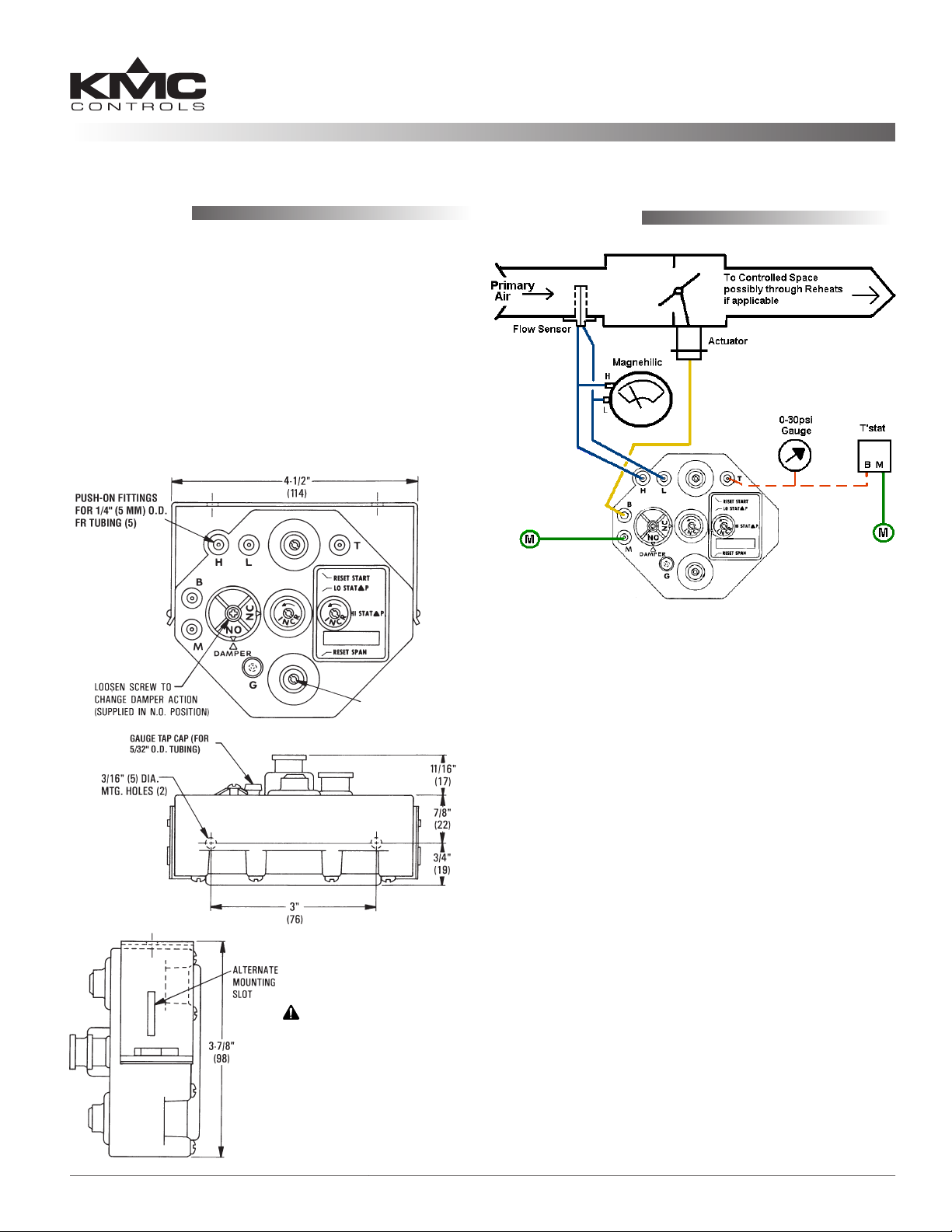
Connections
Magnehelic gauge and 0–30 psi
gauge in illustration added for
checkout and calibration purposes
Typical CSC-3011 Application and Connections
For adjusting start
point and span (upper
and lower knobs) see
the Application Guide
All dimensions are in inches (mm)
CAUTION
Pneumatic devices
must be supplied with
clean, dry control air.
Any other medium
(e.g., oil or moisture
contamination) will
cause the device to fail.
For all models of the CSC-3000 series, use 1/4" (5 mm)
O.D. “FR” tubing on the following push-on ings:
1. Connect the clean, dry, oil-free main air supply to Port
“M” (15 to 30 psi).
2. Connect the damper actuator to Port “B”.
3. Connect the thermostat output to Port “T”.
4. Connect the high pressure tap on the air ow sensor to
Port “H”.
5. Connect the low pressure tap on the air ow sensor to
Port “L”.
6. Check for proper connections. Make sure all tubes
are snug on their ings. If loose, trim the end of the
tubing and reconnect it to ensure there are no leaks.
NOTE: Over time, the tube may stretch or develop
microcracks. Trim the end of tube back to
undamaged material and reconnect. Replace the
tubing if it is brile or discolored.
NOTE: You can easily test for leaks with a squeeze
bulb to ensure there are no leaks at the actuator
diaphragm or ings.
7. Use a ow hood or “tee” a Magnehelic® (or equivalent)
dierential pressure gauge between the controller and
the ∆P pick-up to determine ow rates.
CSC-3000 Series 1 Installation Guide
Page 2
Adjustments and Calibration
NOTE: Do NOT adjust start point and span (upper and
lower knobs) without thoroughly reviewing the
Application Guide. For information about direct
vs. reverse reset, see the Application Guide.
Damper Action
REVERSE Reset Minimum and Maximum
Max. Airflow
Reset Start Point
• 3 psig: CSC-3021/3026
• 8 psig: CSC-3011/3016/3017/3025
• 10 psig: CSC-3023
Reset Span (5 psig)
(Cooling w/ RA Thermstat or
Heating w/ DA Thermostat)
Min. Airflow
The damper action is factory-set at Normally Open (NO).
To change to Normally Closed (NC):
1. Loosen the damper selection screw.
2. Turn the selection dial clockwise until the “NC” arrow
aligns with the “DAMPER” arrow.
NOTE: Accuracy in the alignment of the arrows is
very important. Make this adjustment as exact
as possible.
3. Tighten the selection screw. Be sure the screw is tight
(2 to 4 in-lbs. of torque), but if overtightened, the
plastic will strip out.
Adjusting Minimums and Maximums
When adjusting the minimum and maximum ow
seings, the output responds slowly to changes in the
setpoint. Wait for the ow rate to stabilize aer making
an adjustment (usually 20 to 30 seconds) before making
further adjustments. Also, if the damper position is all
the way closed or open when starting this step, turn the
adjustment one full turn, and then wait 20 to 30 seconds
for a change in the ow reading of the Magnehelic gauge.
If no change occurs aer this time, repeat until the ow
rate changes. (See the Application Guide for more tips.)
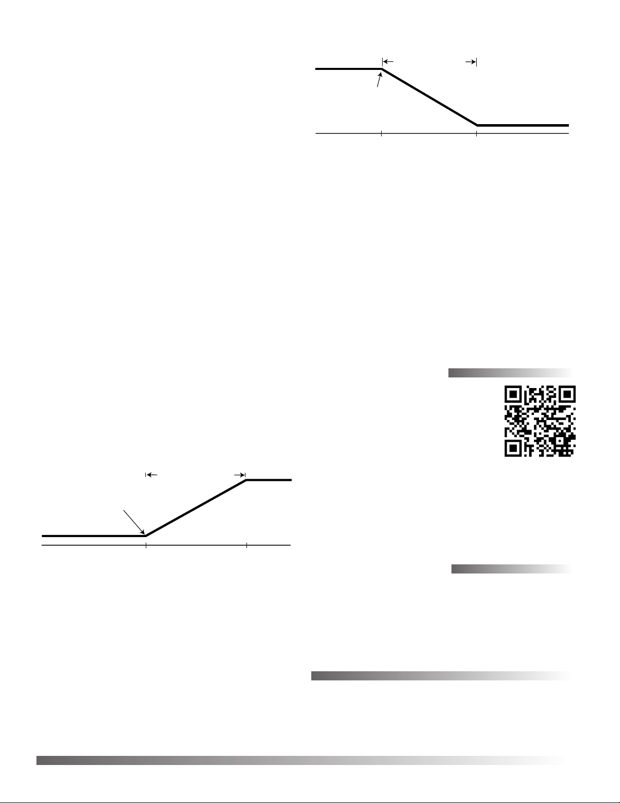
DIRECT Reset Minimum and Maximum
Reset Start Point
• 3 psig: CSC-3021/3026
• 8 psig: CSC-3011/3016/3017/3025
• 10 psig: CSC-3023
Min. Airflow
NOTE: The direct reset illustration above assumes no
relays between the thermostat and “T” port.
For Direct Reset (DA thermostat for cooling or RA
thermostat for heating), perform the following steps:
1. Disconnect the “T” port. Temporarily plug the tubing.
(Do NOT plug the port.)
2. Adjust the LO STAT ∆P (center dial) to the desired
Minimum airow.
3. Reconnect the tubing at “T” port.
4. Adjust thermostat to call for full airow (15 psi or
more at “T” port).
5. Adjust the HI STAT ∆P (dial on right) to the desired
Maximum airow.
6. Repeat Steps 1 through 5 to verify the seings.
Reset Span (5 psig)
Max. Airflow
(Cooling w/ DA Thermstat or
Heating w/ RA Thermostat)
Thermostat Pressure
Thermostat Pressure
NOTE: The reverse reset illustration above assumes no
relays between the thermostat and “T” port.
For Reverse Reset (RA thermostat for cooling or DA
thermostat for heating), perform the following steps:
1. Disconnect the “T” port and leave it open. Temporarily
plug the open tubing.
2. Adjust the LO STAT ∆P (center dial) to the desired
Maximum airow.
3. Reconnect the tubing at port “T”.
4. Adjust the thermostat to call for minimum airow (15
psi or more at “T” port).
5. Adjust the HI STAT ∆P (dial on the right) to the
desired Minimum airow.
6. Repeat Steps 1 through 5 to verify the seings.
More Information
For specications, see the Data Sheet for
these controllers. For additional adjust-
ments, calibration, troubleshooting,
principles of operation, and sample applications, see the Application Guide for
these controllers. For support documents,
see the CSC-3000 series product page (bit.ly/y0G2sI) on
the KMC Controls web site (kmccontrols.com).
This Installation Guide does not apply to the CSC-3014
(designed to work with CTC-2100 Thermostats) or the
CSC-3501/3505 (Linear Volume Reset Controllers). See
their separate Data Sheets and Installation Guides.
Important Notices
The material in this document is for information purposes
only. The contents and the product it describes are subject to
change without notice. KMC Controls, Inc. makes no representations or warranties with respect to this document. In no event
shall KMC Controls, Inc. be liable for any damages, direct or
incidental, arising out of or related to the use of this document.
KMC Controls, Inc.
19476 Industrial Drive
New Paris, IN 46553
574.831.5250
www.kmccontrols.com; info@kmccontrols.com
CSC-3000 Series 2 Installation Guide
© 2012 KMC Controls, Inc. 213-019-01M
 Loading...