

Page 1
Installation Guide
CSC-2000 Series Overview
Reset Volume Controllers
CSC-2000 Series
The CSC-2000s are dierential-pressure (∆P), submaster controllers with adjustable minimum and
maximum airow seings. A master controller,
typically a room thermostat, resets the CSC velocity
setpoint.
CSC-2000s are available as direct acting for normally
open VAV terminal units, and reverse acting for normal closed VAV terminal units. Each unit is equipped
with separate adjustment knobs for minimum and
maximum airow seings. CSC-2001/2002s are
equipped with 0–10 reference dials, while all others
have blind adjustments. Calibrate all models using
standard airow measuring equipment.
The spring range of the actuator does not maer
to the controller. However, sucient main air is
required to provide the actuator with enough force
to operate the damper/linkage.
Any sequencing with other controllers, valves, or
pneumatic-electric relays must be sequenced with
the controller’s reset range, not the actuator’s spring
range.
These controllers are typically used on single-duct
applications but may be found in dual-duct applications. When working on dual-duct applications
it may be necessary to work on one duct at a time
while closing o the other.
The CSC-2000 series controllers are position sensitive. See the Mounting section on the next page for
the proper vertical/horizontal orientation for the different models.
CAUTION
Pneumatic devices must be supplied with clean,
dry control air. Any other medium (e.g., oil or
moisture contamination) will cause the device
to fail.
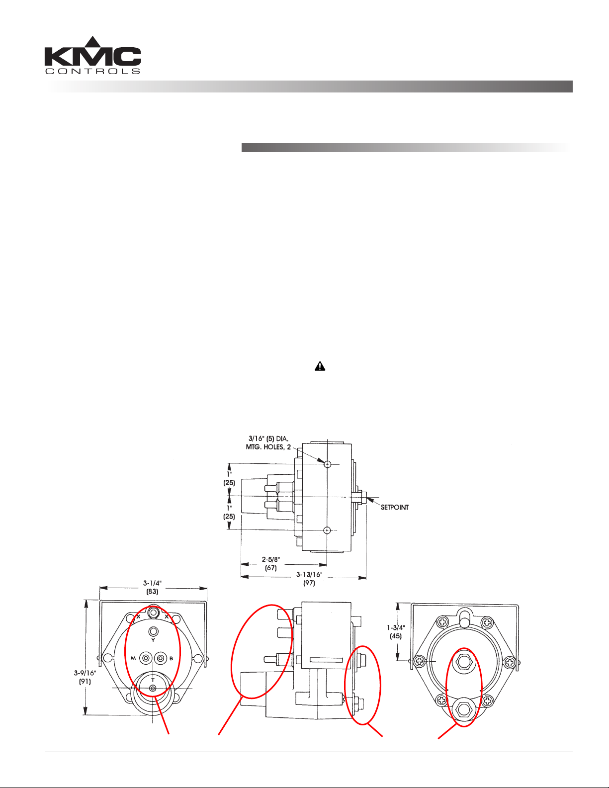
Connections Adjustments
CSC-2000 Series Reset Volume Controllers 1 Installation Guide
Page 2
Specifications
Mounting
Output Sensitivity 0 to 1" range unit,
5 psig/0.02" wg (35 kPa/5 Pa)
0 to 2" range units,
5 psig/0.04"wg (35 kPa/10 Pa)
Main Air Pressure 15 to 30 psig (103 to 207 kPa)
Max. Signal Pressure 6" wg (1493 Pa) applied to
either port (X or Y)
Material Flame retardant plastic (beige
or gray)
Output Capability 0 to supply pressure
Weight 7.5 oz. (213 grams)
Temperature Limits
Operating 40° to 120° F (4° to 49° C)
Shipping –40° to 140° F (–40° to 60° C)
Direct Acting BEIGE units (CSC-2001/2003/2007/
2009/2017) are designed for normally open dampers
with direct-acting thermostats for cooling and reverse-acting thermostats for heating.
As close to the ow sensor pickup as is feasible,
fasten the mounting bracket to the mounting surface
with two self-threading screws in the two 3/16 in.
(5 mm) holes. (Make sure to leave enough room to
make connections.)
The CSC-2000 series are position sensitive:
• The minimum and maximum ow limits must
be set (calibrated) in the same position the
controller will be mounted.
• The CSC-2001/2002 (with 0–10 molded plastic
dials) must be mounted horizontally with dial
adjustment knobs facing up.
• The CSC-2003 through CSC-2018 (no molded
dials) may be mounted horizontally (preferred),
with the adjustment knobs up or down, or
mounted vertically (the diaphragm inside must
be in a horizontal or vertical plane).
NOTE: If replacing a CSC-2001-22 or CSC-2002-22
(designed for vertical mount and now
obsolete), use the CSC-2001 or CSC-2002 as
appropriate and mount dials face up or use
the CSC-2003 or CSC-2004 as appropriate
and mount vertically or horizontally.
Reverse Acting GRAY units (CSC-2002/2004/2008/
2010/2018) are designed for normally closed damp-
ers with reverse-acting thermostats for cooling and
direct-acting thermostats for heating.
For additional specications of particular models,
see the CSC-2000 Data Sheet.
Horizontal Mount, Knobs Up Only
With 0–10 Molded Plastic Dial
(CSC-2001/2002)
Without
Molded Dial
(CSC-2003
through CSC-
2018)
Horizontal Mount
(Preferred, Knobs Up or Down)
CSC-2000 Series Reset Volume Controllers 2 Installation Guide
Or Vertical Mount
Page 3

Connections
Adjustments and Calibration
All Units
For all models of the CSC-2000 Series use 1/4 in. (6
mm) O.D. “FR” tubing for the following connections:
1. Connect the main air supply to port “M”.
2. Connect the actuator to port “B”.
3. Connect the thermostat to port “T”.
Beige Units
Use 3/8 in. O.D. “FR” tubing with a maximum
length of 24 in. to connect:
1. High pressure to port “X”.
2. Low pressure to port “Y”.
Gray Units
Use 3/8 in. O.D. “FR” tubing with a maximum
length of 24 in. to connect:
1. Low pressure to port “X”.
2. High pressure to port “Y”.
CAUTION
Pneumatic devices must be supplied with clean,
dry control air. Any other medium (e.g., oil or
moisture contamination) will cause the device
to fail.
Troubleshooting
The CSC-2000 series are position sensitive. Be sure
to mount the controller with the correct orientation.
See the Mounting section.
NOTE: If the controller is calibrated in a position
other than the nal mounting position, the
calibration (minimum and maximum ow
limits) will be o.
To minimize issues related to pressure, always use
3/8 in. tubing for the “X” and “Y” ports and keep
the tubing lengths as short as possible. If the sensor has 1/4 in. ings, use 3/8 in. tubing and adapters at the sensor.
Some older style ow sensors may have restrictive
openings for the low pressure pickup. Replacement
of the ow sensor pickup may be necessary.
For additional troubleshooting information, see the
CSC-2000 Applications Guide.
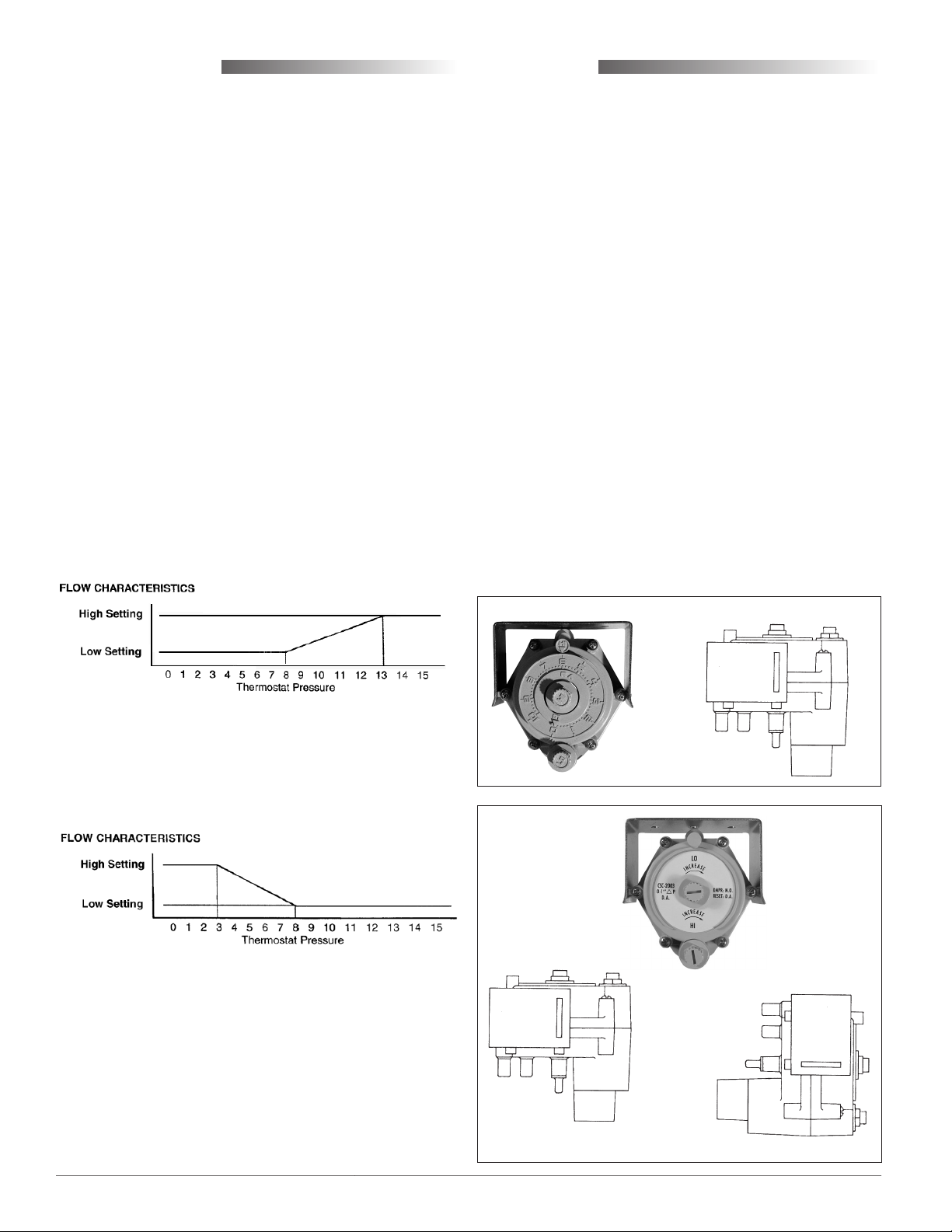
GRAY Controllers (Reverse Acting)
1. Check that there is 0 psi at the “T” Port.
®
2. Use a ow hood or “tee” a Magnehelic
equivalent) dierential pressure gauge between
the controller and the ∆P pick-up.
3. The “HI” ow seing limit (center knob) must
be set rst. Temporarily adjust the thermostat
for a branch pressure lower than the 3 psig reset
start point (maximum cooling); typically 1 psig or
less is best. Removing the thermostat branch line
would be another acceptable method. Adjust the
“HI” knob (center knob) counterclockwise to increase or clockwise to decrease ∆P limit. Normally
one-half turn will cause a 0.1 ∆P change. Allow
for reaction time. Depending on actuator size and
position, timing will vary. To position an actuator/damper from closed to open may take several
minutes.
4. The “LO” ow seing limit must be set aer the
“HI”. Temporarily adjust the thermostat for a
branch pressure higher than the 8 psig reset stop
point (minimum cooling); typically 12 psig or
greater is best. Removing the thermostat branch
line and teeing-in to the main air line would be
another acceptable method. Adjust the “LO” knob
(outside knob) counterclockwise to increase or
clockwise to decrease ∆P limit. Normally one-half
turn will cause a 0.1 ∆P change. Allow for reaction
time.
5. Recheck the “HI” and the “LO” seings at least
twice, verify seings, and ne tune each time if
necessary. This procedure will remove internal
component tensions and conrm seings.
6. Reconnect the thermostat branch line if necessary,
and adjust the thermostat to the desired room
temperature setpoint.
NOTE
NOTE
NOTE: For principles of operation and sample
: The “LO” adjustment limits the travel of
the reset mechanism. Therefore, the reset
span will be less than 5 psig, the upper limit
being less than 8 psig.
: Always make adjustments in the same
plane/orientation as the one in which the
unit will operate.
applications, see the CSC-2000 Applications
Guide.
(or
CSC-2000 Series Reset Volume Controllers 3 Installation Guide
Page 4

BEIGE Controllers (Direct Acting)
1. Check that there is 0 psi at the “T” Port.
2. Use a ow hood or “tee” a Magnehelic® (or equivalent) dierential pressure gauge between the
controller and the ∆P pick-up.
3. The “LO” ow seing limit (center knob) must
be set rst. Temporarily adjust the thermostat
for a branch pressure lower than the 8 psig reset
start point (minimum cooling); typically 6 psig or
less is best. Removing the thermostat branch line
would be another acceptable method. Adjust the
“LO” knob (center knob) clockwise to increase or
counterclockwise to decrease ∆P limit. Normally
one-half turn will cause a 0.1 ∆P change. Allow
for reaction time. Depending on actuator size and
position, timing will vary. To position an actuator/damper from closed to open may take several
minutes.
NOTE: If the “LO” ow seing limit must be set at
“0” (zero minimum), do not turn the “LO”
knob fully counterclockwise. The knob will
adjust three to four full turns aer a zero
minimum is reached. Turning the “LO”
knob fully counterclockwise will result in
a negative reset condition. This means that
when the controller is beginning to reset
at 8 psig from the thermostat, it must rst
overcome the negative adjustment and will
not begin to reset until a higher thermostat
reset pressure is reached. This negative
reset will also reduce the eective range
of the controller by reducing the high end
and narrowing the reset span. If a zero
minimum is required, adjust the “LO” knob
until the controller just begins to crack the
damper open, then back-o one-fourth turn
and verify zero airow.
4. The “HI” ow seing limit (outer knob) must be
set aer the “LO”. Temporarily adjust the thermostat for a branch pressure higher than the 13
psig reset stop point (maximum cooling); typically
17 psig or greater is best. Removing the thermostat branch line and teeing-in to the main air line
would be another acceptable method. Adjust the
“HI” knob (outer knob) clockwise to increase or
counterclockwise to decrease ∆P limit. Nominally
one-half turn will cause a 0.1 ∆P change. Allow for
reaction time.
5. Recheck the “LO” and the “HI” seings at least
twice, verify seings, and ne tune each time if
necessary. This procedure will remove internal
component tensions and conrm seings.
6. Reconnect the thermostat branch line if necessary,
and adjust the thermostat to the desired room temperature setpoint.
NOTE
NOTE
: The “HI” adjustment limits the travel of
the reset mechanism. Therefore, the reset
span will be less than 5 psig, the upper limit
being less than 13 psig.
: Always make adjustments in the same
plane/orientation as the one in which the
unit will operate.
Maintenance
No routine maintenance is required. Each component is designed and manufactured for reliability
and performance. Careful installation and use will
ensure long-term dependability.
CAUTION
Pneumatic devices must be supplied with clean,
dry control air. Any other medium (e.g., oil
or moisture contamination) will result in the
device’s eventual failure.
More Information
For additional specications of particular models,
see the CSC-2000 Data Sheet (hp://bit.ly/PWVwol).
For principles of operation, troubleshooting, and
sample applications, see the CSC-2000 Applications
Guide (hp://bit.ly/RAWIzn).
(Scan QR code
to download
Applications
Guide.)
KMC Controls, Inc.
19476 Industrial Drive
New Paris, IN 46553
574.831.5250
www.kmccontrols.com; info@kmccontrols.com
CSC-2000 Series Reset Volume Controllers 4 Installation Guide© 2012 KMC Controls, Inc. 205-019-01R
 Loading...