

Page 1
BAC-5051 BACnet Router
Installation Guide
Complete the following steps to install a
Conquest™ BAC-5051 BACnet Router.
Refer to the Conquest BAC-5051E BACnet Router
data sheet for router specic information on the
web at kmccontrols.com.
INSTALL CONTROLLER
NOTE: Complete steps 1–2 to install the
router with screws.
Complete steps 3–7 to install the
router on a 35 mm DIN rail.
NOTE: Install the router in a metal UL
approved energy management
equipment panel.
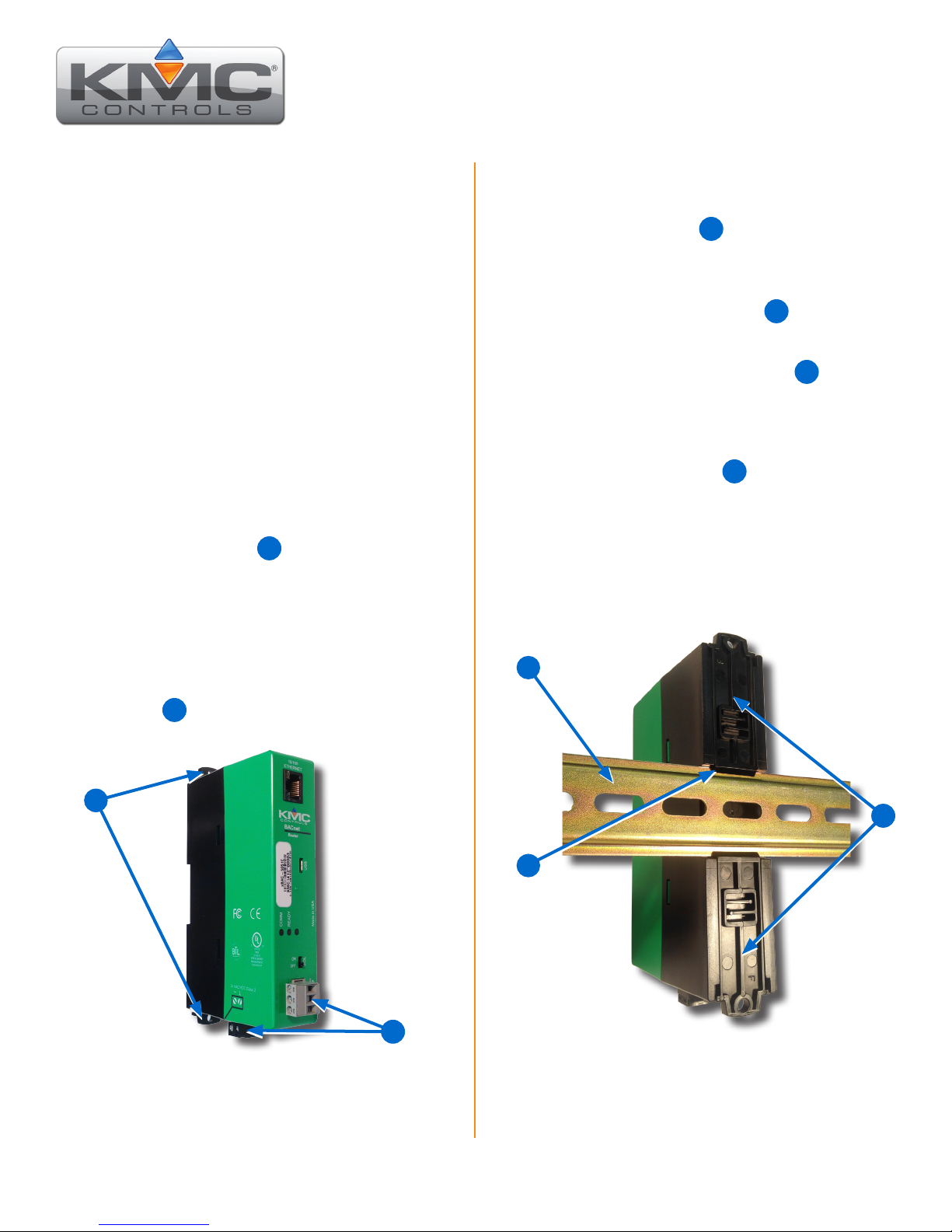
1. Position the router so the removable color
coded terminal blocks 1 are easy to access
for wiring.
NOTE: The black terminals are for power. The
gray terminals are for communication.
NOTE: Complete steps 3–7 to install the
router on a 35 mm DIN rail.
3. Position the DIN rail 3 so that when the
router is installed the color coded terminal
blocks are easy to access for wiring.
4. Pull out one of the DIN Latch 4 until it clicks
once.
5. Position the router so the top tab 5 of the
DIN release rests on the DIN rail.
6. Lower the router against the DIN rail.
7. Push in both DIN Latch 4 to engage the DIN
rail.
NOTE: To remove the router, pull the DIN
Latch until it clicks once and lift the
router off the DIN rail.
2. Screw a #6 sheet metal screw through the
mounting tab of the DIN Latch on each end of
the router 2.
2
1
NOTE: Pull out each DIN Latch mounting tab
one click to be 6 inches on center for
mounting.
3
4
5
KMC Controls, 19476 Industrial Drive, New Paris, IN 46553 / 877-444-5622 / Fax: 574-831-5252 / www.kmccontrols.com
Page 2
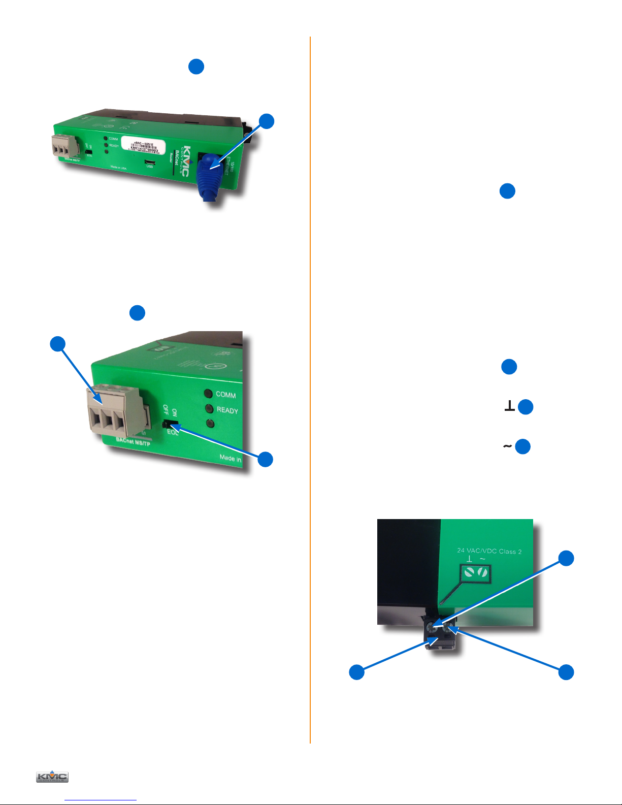
CONNECT ETHERNET NETWORK
8. Connect an Ethernet cable 6 to the 10/100
ETHERNET port.
6
NOTE: For principles and good practices
when connecting an MS/TP network,
see Planning BACnet Networks
(Application Note AN0404A).
SELECT END OF LINE (EOL)
NOTE: The EOL switch is shipped from KMC
in the OFF position.
14. If the router is at either end of a BACnet MS/TP
network, turn the EOL switch 8 to ON.
NOTE: The Ethernet cable should be a CAT 5
or better and a maximum of 328 feet
(100 meters) between devices.
CONNECT BACNET MS/TP NETWORK
9. Wire the network to the gray BACnet MS/TP
terminal block 7.
7
8
NOTE: 18 gauge AWG shielded twisted pair
cable with maximum capacitance of 51
picofarads per foot (0.3 meters) for all
network wiring (Belden cable #82760 or
equivalent).
CONNECT POWER
NOTE: Follow all local regulations and wiring
codes.
NOTE: Use either shielded connecting cables
or enclose all cables in conduit to
maintain RF emissions specications.
NOTE: Connect a 24 VAC, Class-2 transformer
capable of supplying 8 VA to the black
power terminal block 9 of the router.
15. Connect the neutral side of the transformer to
the router's common terminal ⊥ 10.
16. Connect the AC phase side of the transformer
to the router's phase terminal ∼ 11.
10
10. Connect the –A terminals in parallel with all
other –A terminals on the network.
11. Connect the +B terminals in parallel with all
other +B terminals on the network.
12. Connect the shields of the cable together at
each device using a wire nut or the S terminal
on the controllers.
13. Connect the cable shield to a good earth
ground at one end only.
BAC-5051 BACnet Router Installation Guide 2 922-019-01B
9
11
Page 3

POWER & COMMUNICATION
AMBER ETHERNET LED
15
The status LEDs indicate power connection and
network communication.
NOTE: If neither the green READY LED nor
the amber COMM LED is ON, check
the transformer fuse, power, and
connections to the router.
GREEN READY LED
The green READY LED flashes once per
12
second, indicating running.
13
12
AMBER BACnet MS/TP COMM LED
The amber COMM LED flashes at a one-half-
13
second rate when looking for other devices to
pass the token.
The amber COMM LED flickers as it receives
and passes the token over the BACnet MS/TP
network.
The amber Ethernet LED flashes when the
router is communicating with the network.
The amber Ethernet LED is OFF when the
controller is communicating with the network
at 10 Mbps.
1514
ROUTER SET UP
Set up and conguration of the router is done
through a web browser (Internet Explorer version
9 or later or an HTML5 supported web browser)
using the routers IP address (192.168.111.252).
Refer to the Router Application Guide for more
conguration information.
REPLACEMENT PARTS ................ PART NUMBER
Replacement Pack of Conquest controller
terminal blocks and DIN clips .................HPO-9901
ETHERNET LEDs
The Ethernet status LEDs indicate network
connection and communication speed.
NOTE: If neither the green Ethernet LED
nor the amber Ethernet LED is ON,
check the power and network cable
connections.
GREEN ETHERNET LED
The green Ethernet LED stays lit when the
14
router is connected to the network.
The green Ethernet LED is OFF when the router
is not powered or not communicating with the
network.
IMPORTANT NOTICES
The material in this document is for information
purposes only.
The contents and the product it describes are
subject to change without notice.
KMC Controls, Inc. makes no representations or
warranties with respect to this document.
In no event shall KMC Controls, Inc. be liable for
any damages, direct, or incidental, arising out of or
related to the use of this document.
The KMC logo is a registered trademark of KMC
Controls, Inc. All rights reserved.
TEL: 574.831.5250
FAX: 574.831.5252
e-mail: info@kmccontrols.com
© 2015 KMC Controls, Inc. Specifications and design subject to change without notice 922-019-01B
 Loading...