

Page 1
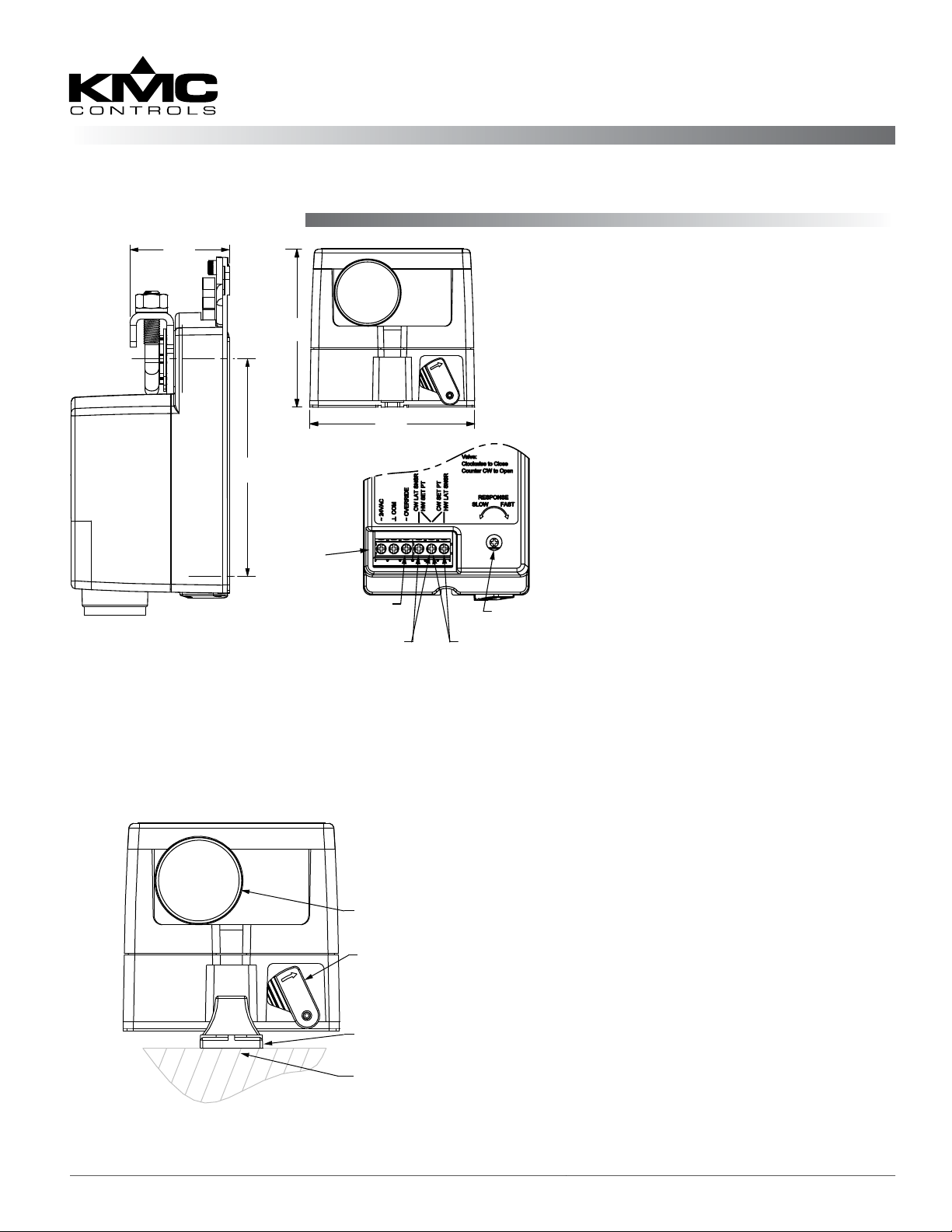
CEP-4703 Mounting
Analog Electronic DAT Controller-Actuator
CEP-4703/4703V
Installation Guide
1.568 [40]
2.5
[63.5]
3.437
[87.3]
CEP-4703
Terminals
(under cover)
Override input (remembers
position and closes valve on
no call
2.6
[66]
for heat or cool)
Cold water LAT sensor or
hot water setpoint resistor
Sensitivity
adjustment
Cold water setpoint
resistor or hot water
LAT sensor
NOTE: Thismountingsectionisspecic
to the CEP-4703. For mounting a
CEP-4703V, see CEP-4703V Valve
Mounting on page 2.
1. Ensure the damper or valve shaft can
move freely through its entire range
of motion, and x any binding before
installing the actuator. Turn the damper
blade to its fully closed position.
2. Press (to the right) and hold the gear
disengagement lever, rotate the actuator
to the fully closed position, and release
the lever.
NOTE: Depending on the damper-seal
design, backing the actuator o
its stop approximately 5° may
provide tight damper shut-o.
3. Align the actuator and slide it onto the
shaft.
4. Leaving a gap between the actuator
and mounting surface to prevent any
binding, nger-tighten the nuts on the
V-bolt.
5. Insert the non-rotation bracket (HMO4002 supplied or HMO-4001 “T” bracket
available separately) into the slot at the
base of the actuator (as shown in the
illustration).
6. Secure the non-rotation bracket with
two (2) #8 or #10 self-tapping screws.
Removeable conduit fitting
with 1/2" NPS threaded hole
7. Evenly tighten the V-bolt nuts 30 to 35
in-lb.
Gear disengagement lever
8. If desired, use a 7/64-inch hex key
wrench to loosen and position the endstop screw.
Non-rotation bracket
(HMO-4002)
Mounting surface
NOTE: The two holes at the top of the
actuator are NOT for use in
direct-coupled applications.
They are for remote mounting,
such as with the optional HLO4001 Crank Arm Kit (see the Data
Sheet).
CEP-4703/4703V 1 Installation Guide
Page 2
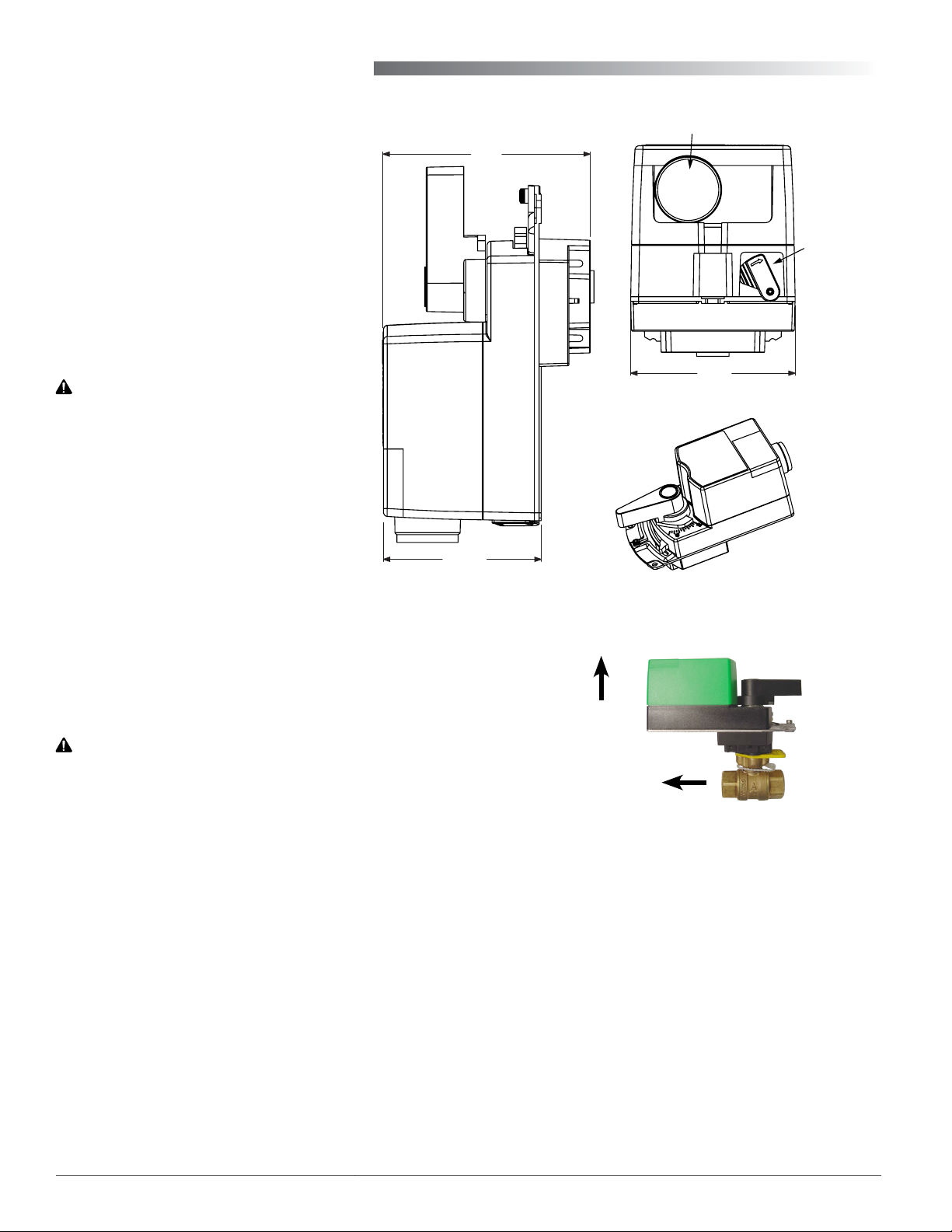
CEP-4703V Valve Mounting
3.437
[87.3]
1.568 [40]
2.6
[66]
[63.5]
2.5
CEP-4703
Override input (remembers
position and closes valve on
no call
for heat or cool)
Cold water LAT sensor or
hot water setpoint resistor
Cold water setpoint
resistor or hot water
LAT sensor
Sensitivity
adjustment
Terminals
(under cover)
NOTE: To assemble a quick-mount
“V” actuator on a valve
body, see the HPO-5074
Installation Guide on the
KMC web site.
1. Clean the lines upstream from the
valve. Remove any debris larger
than 0.06" (0.015 mm).
2. Align the valve’s ow indicator
with the system ow.
3. Mount the valve so the actuator is
positioned over the valve body.
CAUTION
To prevent condensation from dripping
onto the actuator housing, mount the
valve with the actuator in the upright
position or, at most, at a 45° angle.
4. Seal valves with approved pipe
sealant.
5. Using two wrenches, secure the
valve to the pipe. Torque should
not exceed 75 ft-lb. (102 N
•m).
2.5
[63.3]
3.28
[83.2]
CEP-4703V
Removable conduit fitting
with 1/2" NPS threaded hole
2.6
[66]
Gear
disengagement
lever
6. Eliminate air from the system to
keep the valves full of uid during operation.
NOTE: If the system experiences large amounts of
debris, steps should be taken to keep the
system clean.
CAUTION
Using mineral oil lubricants or other incompatible
substances in system fluids may damage EPDM
rubber seals in valves. Before using any lubricant or
additive in a water or ethylene glycol base, consult
the substance manufacturer for compatibility with
EPDM (Ethylene Propylene Diene Monomer).
CEP-4703V Actuator
UP
SYSTEM FLOW
VFB-43 Series Valve Body
ACTION:
Full CW = Valve Closed (System Off)
Full CCW = Valve Open (System On)
CEP-4703/4703V 2 Installation Guide
Page 3

Wiring Connections
1. Loosen the screw on the conduit ing and lift up
to remove the ing.
2. Using a utility knife or drill, cut the red plug
to accept wiring or replace the plug with an
application-specic ing.
NOTE: The red plug (or similar ing) protects
internal components from debris, helping to
ensure long actuator life.
3. Thread wires through the plugged opening and
connect to the terminal block as shown.
4. Reinstall the conduit ing and tighten the screw.
Setpoint Resistor*
°F Ohms °F Ohms
Chilled Water Hot Water
54 16.9K 94 6.98K
56 16.2K 96 6.65K
58 15.4K 98 6.34K
60 14.7K 100 6.04K
62 14.0K 102 5.90K
*1/4 Watt, 1%
Configured for Cooling
24 VAC
Contact
STE-1401
Setpoint Resistor
Configured for Heating
24 VAC
Contact
Setpoint Resistor
STE-1401
Contact Closed = System On; Open = System Off
CW to Close; CCW to Open
Operation
After the mechanical and electrical installations have
been completed, cycle the actuator to verify the direction of rotation for normal operation.
When the CEP-4703/4703V is connected to power:
1. The actuator drives to the fully closed position
(for two minutes). If the Override signal is present (contact closed across two terminals), indicating system On, the actuator waits one more minute and then starts controlling. If the Override
Control Sequence
100
100
% On Time
% On Time
0
0
CLOSE 1F SP 1F OPEN
signal is absent (contact open), indicating system
O, the actuator waits in the closed position.
2. Whenever the system goes O, the actuator
stores its current position and then drives to the
fully closed position.
3. Whenever the system goes On, the actuator re-
turns to its previous (stored) position, waits one
minute, and resumes controlling.
When controlling, the CEP-4703/4703V control sequence is as shown in the diagram.
% On-Time Slope Adjustable Via Sensitivity Adjustment
Maximum = 30% per °F (faster response but less stable)
Minimum = 3% per °F (slower response but more stable)
% On-Time Period = 1 Minute
CEP-4703/4703V 3 Installation Guide
Page 4

Troubleshooting
No Rotation or Wrong Stroke Range
More Information
NOTE: Pausing for up to two minutes is part of
normal operation. See Operation on page
3.
• Check that the shaft moves freely. (Press and
hold the gear disengagement lever and manually
rotate the shaft.)
• Check wiring. (See Wiring Issues section below.)
• Check for a tripped circuit breaker to the
transformer, for proper supply voltage from the
transformer (or power supply), and for enough
capacity (VA) for all connected devices. See their
respective data sheets and Tips for Connecting
24-Volt Power Application Note (AN0604D)
available on the KMC Controls web site.
• Check the adjustable stop position.
Wiring Issues
• Check for correct wiring at the each device.
• Use a voltmeter and ohmmeter to check the
terminals for expected values.
• See Tips for Connecting 24-Volt Power Applica-
tion Note (AN0604D).
For specicationsand
other information, see
the CEP-4703/4703V
Data Sheet on the KMC
web site.
For information on
assembling a quickmount CEP-4703V
actuator on a valve
body, see the HPO-5074
Installation Guide.
NOTE: Wiring must be adequate to avoid
excessive voltage drop on long runs! Allow
plenty of “cushion” in measurements. A
meter may be too slow to register transient
dips or peaks during startup.
Maintenance
No routine maintenance is required. Careful
installation will also ensure long term reliability and
performance.
Accessories
HCO-1151 Weather shield kit
HLO-4001 Crank arm kit
HMO-4001 Non-rotation “T” bracket
HMO-4002 Replacement non-rotation
bracket
STE-1401 Duct temperature sensor (Type
III, 10K)
Important Notices
The material in this document is for information
purposes only. The contents and the product it
describes are subject to change without notice. KMC
makes no representations or warranties with respect
to this document. In no event shall KMC be liable for
any damages, direct or incidental, arising out of or
related to the use of this document.
KMC Controls, Inc.
19476 Industrial Drive
New Paris, IN 46553
574.831.5250
www.kmccontrols.com
info@kmccontrols.com
CEP-4703/4703V 4 Installation Guide
© 2014 KMC Controls, Inc. 036-019-05A
 Loading...