

Page 1
Pneumatic-Electric Relays, Single and Multi-Stage
Installation Guide
CCE-3000 Series
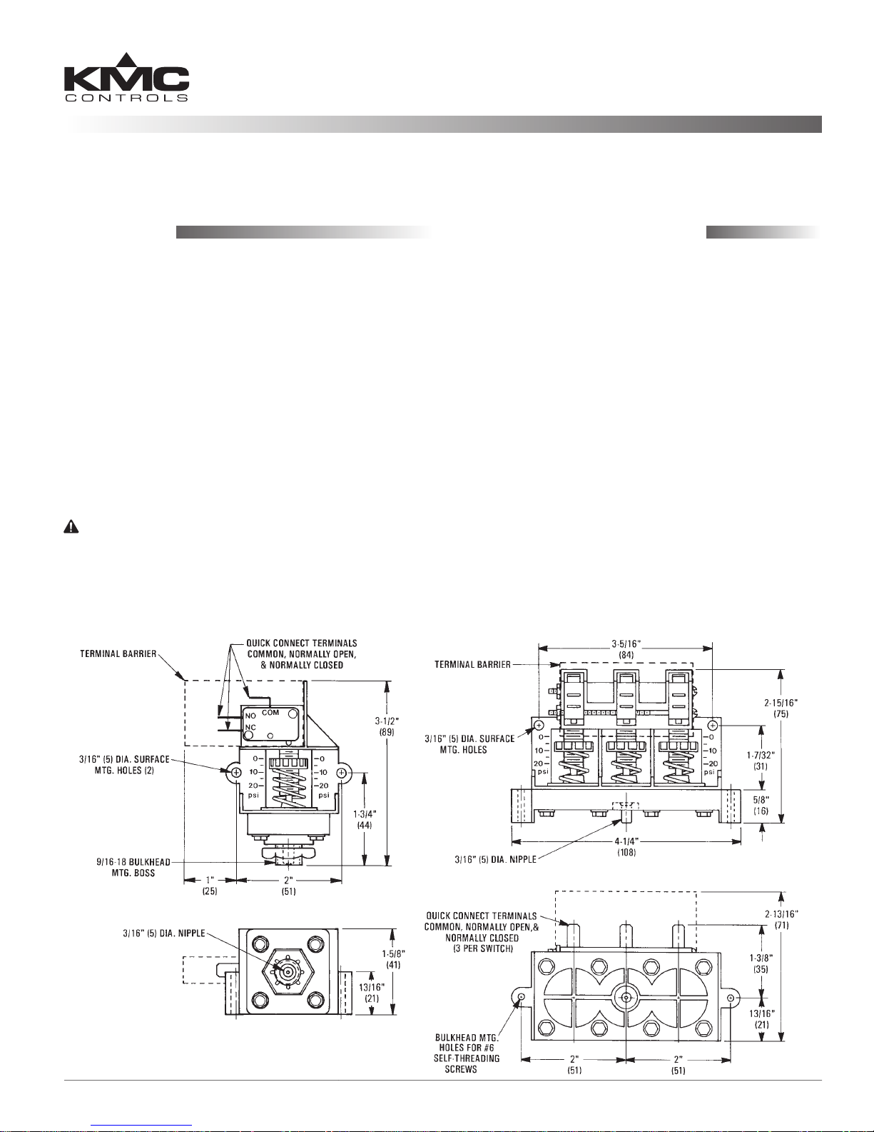
Mounting
The CCE-3000 Series relays are not position sensitive
and may be mounted in any orientation.
Model CCE-3001
1. Surface mount using the two 3/16" diameter
holes.
2. Bulkhead mount using the 9/16-18 boss and nut.
Model CCE-3002/3003
1. Surface mount using the two 3/16" diameter
holes.
2. Bulkhead mount using two #6 self-threading
screws.
CAUTION
Pneumatic devices must be supplied with clean, dry
control air. Any other medium (e.g., oil or moisture
contamination) will cause the device to fail.
CCE-3001 CCE-3003
Connections and Wiring
Electrical
Connections are made to 1/4" quick connect terminals. Do not exceed the electrical ratings of the
switches (see Specications on page 2).
1. Connect to the Common “C” and Normally Open
“NO” terminals if a fall in signal should break the
circuit.
2. Connect to the Common “C” and Normally
Closed “NC” terminal if a fall in signal should
make a circuit.
Air Supply
1. Using 1/4" (6 mm) OD polyethylene tubing,
connect the signal to the 3/16" (5 mm) inlet in the
boom of the unit.
2. Limit the signal to 30 psig (207 kPa) max.
CCE-3000 Series 1 Installation Guide
Page 2
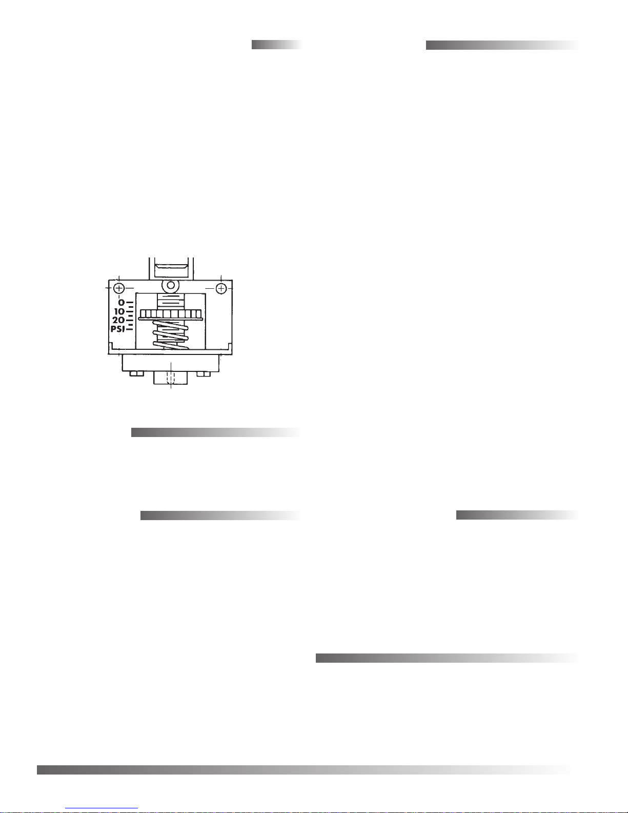
Adjustments and Calibration
Specifications
1. Choose a setpoint between 2 and 20 psi (14 and
138 kPa).
NOTE:
2. Turn the setpoint adjustment wheel until the
3. Repeat for each switch.
NOTE: A gauge may be installed before completing
The dierential on these models is 1 psi
minimum and 2 psi maximum (7 and 14
kPa).
boom of the wheel lines up with the signal
pressure listed beside the spring.
Step 2 to calibrate the relay to a particular
signal pressure.
Setpoint Range 2 to 20 psi (14 to 138 kPa)
Dierential Fixed dierential, 1 to 2 psi
nominal (7 to 14 kPa)
Pressure Max.
Connections
Air 3/16" (5 mm) nipples for 1/4" (6
Electrical 1/4" quick-connect terminals
Switching Action SPDT each stage
Electrical Ratings 25 amps each switch (non-
Weight
CCE-3001 2 oz. (57 grams)
CCE-3002 4.5 oz. (128 grams)
CCE-3003 5 oz. (142 grams)
Material
Housing Black polycarbonate
Diaphragm Silicone
30 psi (207 kPa)
mm) O.D. polyethylene
tubing
inductive) @ 120/240/277 VAC,
1 HP @ 125 VAC, 2 HP @ 250
VAC, 750 VA pilot duty
Accessories
ICI-1005 Pressure gauge
Maintenance
No routine maintenance is required. Careful installation will help ensure dependable, long-term reliability and performance.
Temperature Limits
Operating 40 to 150° F (4 to 60° C)
Shipping –40 to 150° F (–40 to 60° C)
Approvals
UL recognized
Patent Number 4,855,545 (CEE-3002/3003)
Important Notices
The material in this document is for information
purposes only. The contents and the product it
describes are subject to change without notice.
KMC Controls, Inc. makes no representations or
warranties with respect to this document. In no event
shall KMC Controls, Inc. be liable for any damages,
direct or incidental, arising out of or related to the
use of this document.
KMC Controls, Inc.
19476 Industrial Drive
New Paris, IN 46553
574.831.5250
www.kmccontrols.com
info@kmccontrols.com
CCE-3000 Series 2 Installation Guide
© 2012 KMC Controls, Inc. 155-019-01E
 Loading...