

Page 1
Dual Input Receiver Controllers
Installation Guide
ConnectionsMounting
CCC-1001/1002
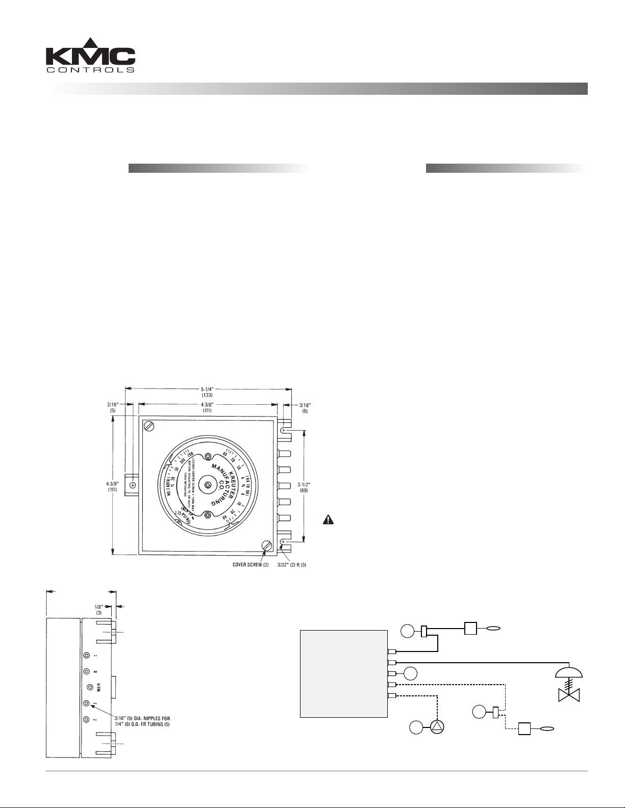
The CCC-1001 and CCC-1002 are not position sensitive, but they must be calibrated and mounted in the
same orientation.
1. Locate the three mounting ears (anges) on the
unit.
2. Place the controller on the mounting surface and
mark the locations of the two top ears.
3. Partially install two mounting screws (#8 or #10)
on the marks. These should be 3-1/2" (89 mm)
apart.
4. Slide the top ears under the screws.
5. Install the third mounting screw in the boom ear
and tighten all three screws.
The units are supplied as Direct Acting (DA). If
Reverse Acting (RA) is required:
1. Locate the tubing connections on the back of the
controller.
2. Cut the branch tubing at the DA connection
(lower right corner).
3. Remove tubing from the two-prong guides.
4. Connect branch tubing to the RA connection
(upper right corner) using brass ings
(provided).
5. Secure extra tubing in the two-prong guides.
A CCC-1001/1002 controller has ve 3/16" (5 mm)
ports to accept 1/4" (6 mm) O.D. polyethylene tubing.
Connect the controller to other units as follows:
1. Main control air to Port M. This should be 20 psig
(137 kPa), 30 psig (207 kPa) max.
2. Primary input, 3–15 psig, to Port 1.
3. Remote setpoint adjustment, 3–15 psig with a +/–
10% oset, to Port 2.
4. Secondary input to Port 3.
CAUTION
Pneumatic devices must be supplied with clean, dry
control air. Any other medium (e.g., oil or moisture
CCC-1001 =
2-3/16" (56 mm);
CCC-1002 =
2-5/16" (59 mm)
CCC-1001/1002 (Dual Input Receiver Controllers) 1 Installation Guide
CCC-1001 Shown
Secondary Input: 3
Remote Setpoint: 2
contamination) will cause the device to fail.
M
Primary Input: 1
Output Signal: B
Main Air: MAIN
Optional Remote
Restrictor
M
Regulator
M
Setpoint Adjust
(sensed medium, e.g., hot water)
Restrictor
M
Optional Secondary Transmitter
(sensed medium, e.g., outside air)
Primary Transmitter
Controlled
Device
Page 2
Adjustments and Calibration
CCC-1001 Controller
NOTE: Throling range is the percent change of
the primary input (Port 1) that causes a
100% change in the branch output (Port B).
Authority is the change in the secondary
input (Port 3) in relation to the change in
the primary input that will cause the same
change in the output and is expressed as a
percentage (see the Authority Calibration
section).
1. Remove cover before making any adjustments.
2. Set the desired throling range:
A. Loosen large center screw (1 turn
maximum).
B. Remove main control air from Port M.
C. Move the setpoint indicator to the desired
% throling range (4 to 40%) on the DA
or RA scale. See the Throling Range
Adjustment section on page 3.
D. Connect main air to “M.”
3. Set the desired authority:
A. Calculate the required authority. See the
Authority Calibration section.
B. Set the authority indicator to the desired
value.
C. Tighten center screw.
4. Adjust the setpoint output by turning the setpoint
screw (located at the lower right of the unit). See
the Setpoint Calibration section on page 3.
5. Reinstall the cover.
CCC-1002 Controller
NOTE: Follow the steps 1 through 4 for adjusting
the CCC-1001, and then continue with steps
5 through 8.
Throttling Range Adjustment
Throling range % can be calculated by the following formula:
Port 1 Units Desired to Make
100% Change in Port B (Output)
Port 1 Primary Input Span
(Same Units as Above)
x
Span of Controlled
12
x 100
Device (psi)
Example: Port 1 is connected to a temperature
transmier with a range of 40 to 240° F
(200° F span). Branch output is controlling
a 3 to 8 psi (5 psi span) device. Desired
throling range is 20° F. Then throling
range % = (20° F)/(200° F) x (12 psi)/(5 psi) x
100 = 24%.
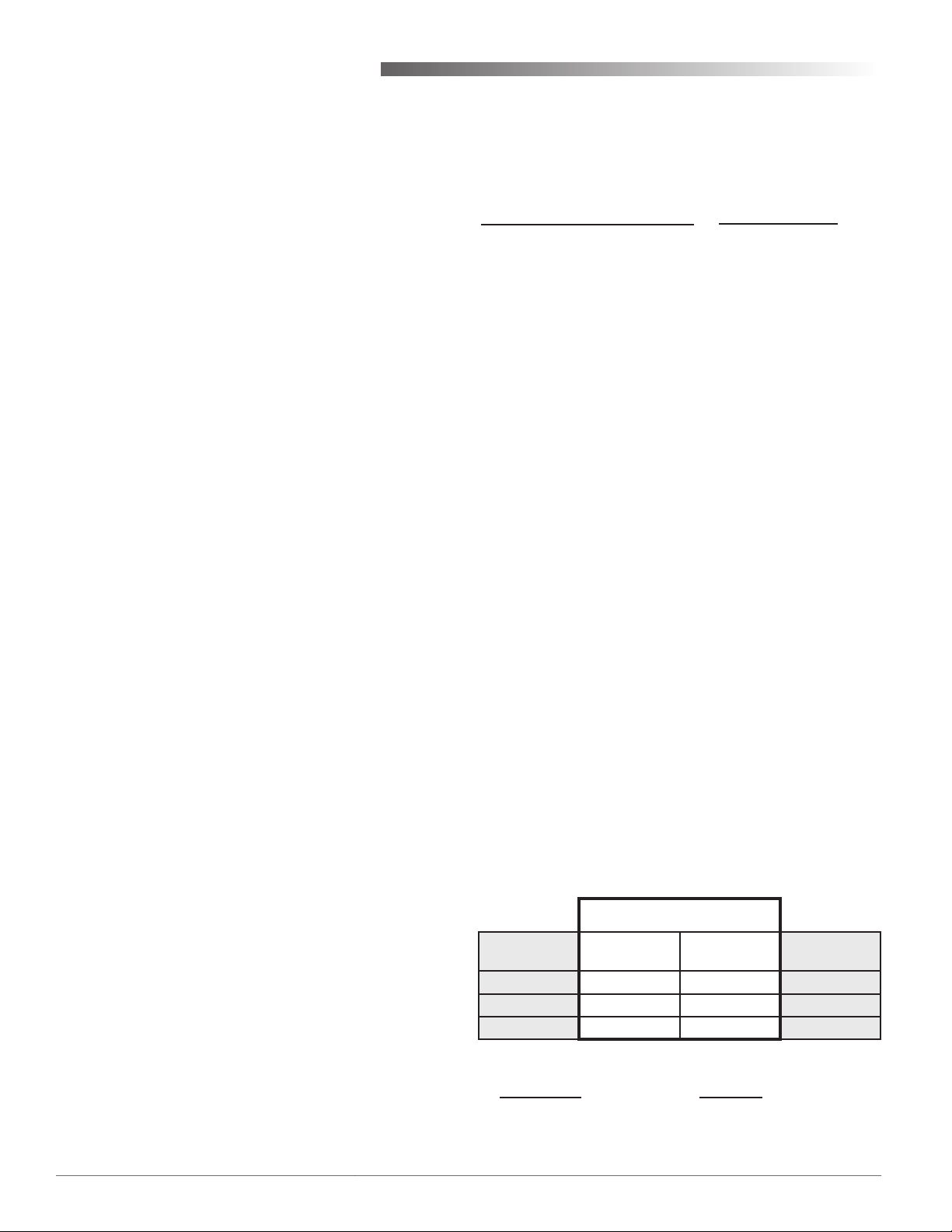
Authority Calibration
This adjustment determines the eect of a secondary
transmier (Port 3) on the setpoint of the receivercontroller.
Example: Reset the HWS (Hot Water Supply)
temperature setpoint based on OAT
(Outside Air Temperature). The HWS
transmier has a range of 40 to 240° F for 3
to 15 psi (0.06 psi/° F), and it is connected
to the Port 1 primary input. The OAT
transmier has a range of –40 to 160° F for 3
to 15 psi (0.06 psi/° F), and it is connected to
the Port 3 secondary input.
NOTE: This example does not compensate for TR
(throling range) across the reset schedule
but assumes a constant branch pressure.
The reset schedule shows the temperatures and pressures at the extreme ends of the operating schedule.
5. Turn the face dial until the desired input signal
(Port 1) pressure value lines up with the clear
arrow indicator.
6. Carefully slide the cover straight down, so that
the cover gear teeth and the setpoint adjustment
sha mesh.
7. Tighten the cover.
8. Apply the adhesive dial face if required.
CCC-1001/1002 (Dual Input Receiver Controllers) 2 Installation Guide
OAT Port #3
Pressure
5.4 psi 0° F 180° F 11.4 psi
7.5 psi 35° F 140° F 9.0 psi
9.6 psi 70° F 100° F 6.6 psi
Authority % =
D P @ Port 1
D P @ Port 3
(D P = Change in Pressure)
Reset Schedule
Outside Air
Temperature
x 100%
Hot Water
Temperature
11.4 – 6.6
=
9.6 – 5.4
HWS Port #1
Pressure
x 100%
(In the Example Above)
= 114%
Page 3

Setpoint Calibration
Initial setpoint calibration is done aer the spring
tube on the back of the controller has been properly
connected and secured and the throling range and
authority adjustments have been set and locked.
1. Make the following connections:
A. Main air supply (20 psi) to MAIN.
B. Branch (output) gauge to Port B.
C. For SINGLE input operation, connect
pressure to Port 1 equal to the desired
setpoint, OR for DUAL input operation,
connect pressures to Ports 1 and 3 that
correspond to the reset schedule at
approximately midrange.
D. If the remote setpoint adjustment is to
be used, connect pressure to Port 2 that
corresponds to zero oset.
E. Unused inputs are le unconnected.
2. Turn the setpoint adjustment screw to obtain an
output equal to the midrange pressure of the
controlled device.
A. If in the DA mode and branch pressure
is high, turn the setpoint screw CW; if
branch pressure is low, turn the setpoint
screw CCW.
B. If in the RA mode and branch pressure
is high, turn the setpoint screw CCW; if
branch pressure is low, turn the setpoint
screw CW.
Aer the system is live, minor adjustments to the
setpoint calibration can easily be done if the setpoint
oset is known. Each complete clockwise rotation, of
the screw, is equivalent to a 1.75 psi increase in Port
1 pressure. To increase the setpoint, turn the adjustment screw CW; to decrease the setpoint, turn the
adjusment screw CCW. The number of turns equals:
Setpoint Offset (° F)
Port 1 Primary Input Span
(° F)
Port 1 Primary Input Span (psi)
x
1.75
Remote Setpoint Adjustment
An input pressure change of 3 to 15 psi to Port 2 will
change the setpoint 20% of the span of the primary
transmier. The eect of the change is direct in
nature. An increase in Port 2 pressure from 9 to 15
psi increases the setpoint 10% and a decrease in Port
2 pressure from 9 to 3 psi decreases the setpoint 10%.
Example: If the Port 1 transmier has a range of 40
to 240° F (200° F span), then the remote
setpoint adjustment pressure on Port 2 can
change the setpoint +/– 20° F or a total of
40° F or 20% of the Port 1 primary input
span.
Accessories
External restrictor HFO-0022 (Restrictor T, 28.8 scim)
might be required if replacing a receiver/controller
using internal restrictors. All transmiers used with
the CCC-1001/1002 require an external restrictor.
For other pneumatic accessories, such as connectors,
tubing, ings, lters, and gauges, see the Compressed Air Accessories section in the Electronic and
Pneumatic Controls Condensed Catalog (SP-071).
Maintenance
No routine maintenance is required. Each component is designed and manufactured for reliability
and performance. Careful installation will ensure
long term dependability.
Example: Port 1 is connected to a temperature
transmier with a range of 40 to 240° F
(200° F span) and an output of 3 to 15 psi
(12 psi span). The desired control point is
7° F higher than the actual control point.
Then, the number of turns = (7°)/(200°)
x (12 psi)/1.75 = 0.24. Thus, the set point
adjustment screw should be turned 1/4 of a
turn CW.
CCC-1001/1002 (Dual Input Receiver Controllers) 3 Installation Guide
Page 4

Competitor Cross-Reference
The CCC-1002 can replace many competitor single/
dual-input receiver/controllers such as:
• Barber-Colman (Schneider Electric) RKS1001/2001/3002/4002
• Honeywell RP908A/RP908B/RP920A/RP920B
• Johnson T-9000 and T-5801/5802
• Robertshaw (Schneider Electric) P341 and 2341
• Siemens 185 and 195 series
A cross-reference of corresponding piping for some
of these controllers is shown in the chart below.
NOTE: External restrictor HFO-0022 might be
required if replacing a receiver/controller
using internal restrictors.
Primary Input: 1
Output Signal: B
Main Air: MAIN
Secondary Input: 3
Remote Setpoint: 2
Optional Remote
M
Restrictor
M
Regulator
M
Setpoint Adjust
Primary Transmitter
(sensed medium, e.g., hot water)
Controlled
Device
Restrictor
M
Optional Secondary Transmitter
(sensed medium, e.g., outside air)
KMC
Ports
CCC-1002 RKS RP908 RP920 T-5800 P341 P541 195
Main Air MAIN M M 1 S M M S
Output Signal B B-c B 2 O B B C
Primary Input 1 1 1 3 CV 1 S 1 or 2
Secondary Input 3 2 2 5 M 3 R 1 or 2
Remote Setpoint 2 RSPA CPA 9 SP 2 C 3
Barber-
Colman
Honeywell Johnson Robertshaw Siemens
KMC Controls, Inc.
19476 Industrial Drive
New Paris, IN 46553
574.831.5250
www.kmccontrols.com; info@kmccontrols.com
CCC-1001/1002 (Dual Input Receiver Controllers) 4 Installation Guide
© 2009 KMC Controls, Inc. 218-019-01E
 Loading...