

KMC Controls BAC-9300 Series, BAC-9301 HPU, BAC-9301 FCU 2-Pipe, BAC-9311 HPU, BAC-9301 RTU Installation Manual
...Page 1
BAC-9300 Series Controller
Installation Guide
CONTENTS
Introduction .............................................. 1
Mount Controller ........................................ 1
Connect Sensors and Equipment .................. 2
Connect (Opt.) Pressure Flow Sensor ............ 3
Connect (Opt.) Ethernet Network .................. 3
Connect (Optional) MS/TP Network............... 4
Connect Power .......................................... 4
Power and Communication Status ................. 4
MS/TP Network Isolation Bulbs .................... 5
Congure/Program the Controller ................. 6
Sample (BAC-9311) Wiring .......................... 7
Input/Output Objects/Connections ................ 8
Replacement Parts ....................................10
Important Notices .....................................10
INTRODUCTION
Complete the following steps to install a KMC
Conquest™ BAC-9300 Series Unitary Controller.
For controller specications, see the data sheet at
kmccontrols.com. For additional information, see
the KMC Conquest Controller Application Guide.
NOTE: The black terminals are for power. The
green terminals are for inputs and
outputs. The gray terminals are for
communication.
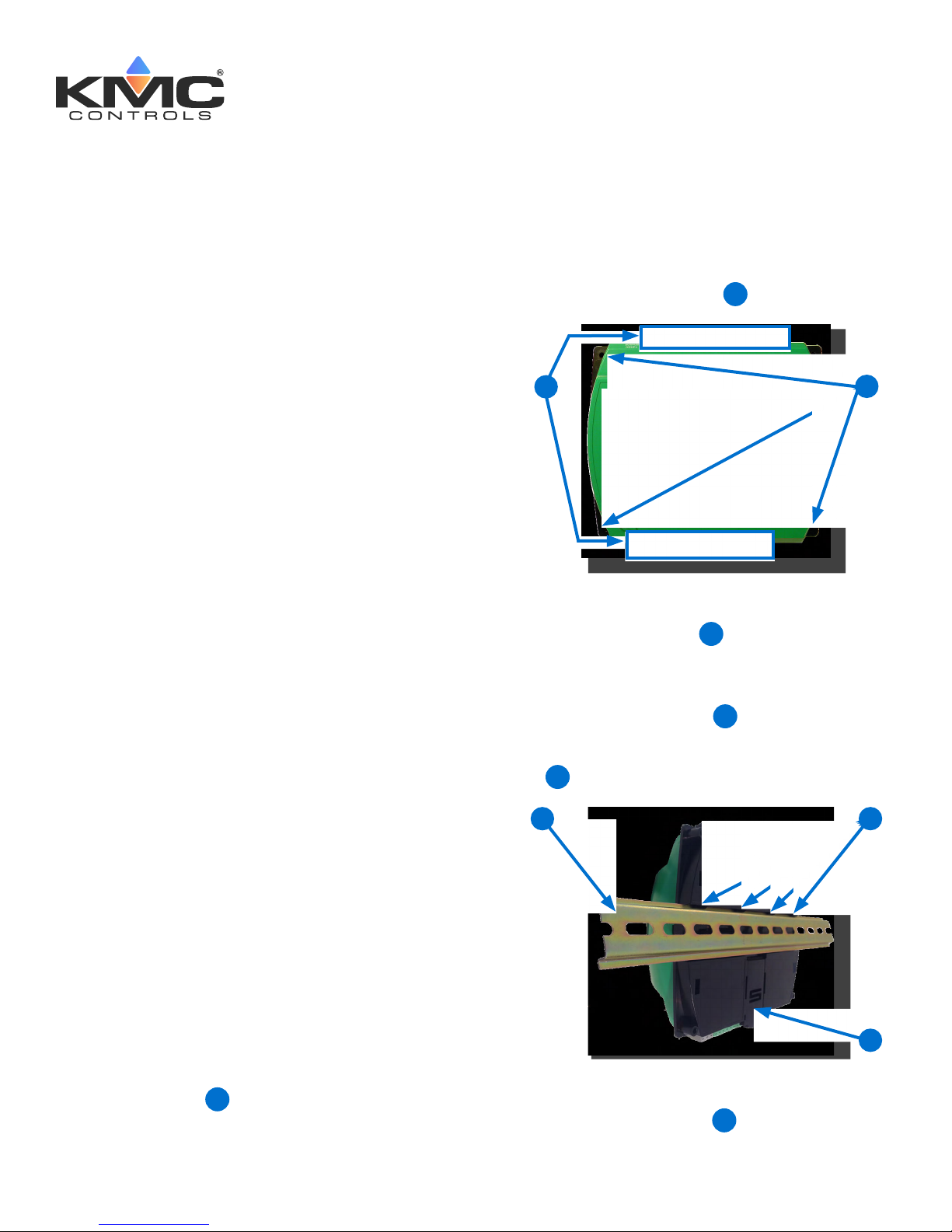
2. Screw a #6 sheet metal screw through each
corner of the controller
1
On a DIN Rail
1. Position the DIN rail
controller is installed the color-coded terminal
blocks are easy to access for wiring.
.
2
so that when the
3
2
MOUNT CONTROLLER
NOTE: Mount the controller inside a metal
enclosure for RF shielding and physical
protection.
NOTE: To mount the controller with screws on
a flat surface, complete the steps in On
a Flat Surface on page 1. Or to mount
the controller on a 35 mm DIN rail
(such as integrated in an HCO-1103
enclosure), complete the steps in On a
DIN Rail on page 1.
On a Flat Surface
1. Position the controller so the color-coded
terminal blocks
wiring.
are easy to access for
1
2. Pull out the DIN Latch
3. Position the controller so that the top four tabs
of the back channel rest on the DIN rail.
5
3
4. Lower the controller against the DIN rail.
5. Push in the DIN Latch
rail.
until it clicks once.
4
to engage the DIN
6
5
4
KMC Controls, 19476 Industrial Drive, New Paris, IN 46553 / 877.444.5622 / Fax: 574.831.5252 / www.kmccontrols.com
Page 2
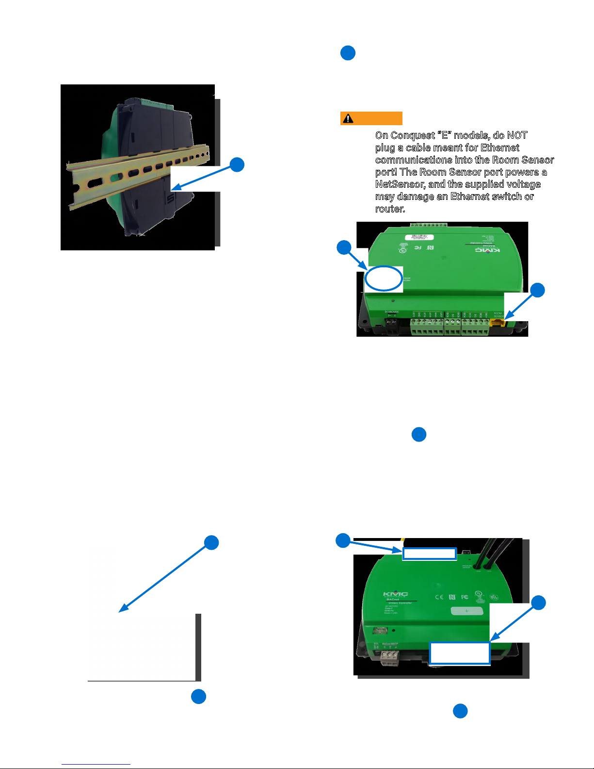
NOTE: To remove the controller, pull the DIN
Latch until it clicks once and lift the
controller off the DIN rail.
CONNECT SENSORS AND EQUIPMENT
NOTE: See Sample (BAC-9311) Wiring on
page 7 and Input/Output Objects/
Connections on page 8 for more
information. See also the YouTube
video KMC Conquest Wiring: BAC-
9300 Series Unitary Controllers.
NOTE: A digital STE-9000 Series NetSensor
can be used for conguring the
controller (see Congure/Program
the Controller on page 6). After the
controller has been congured, an
STE-6010, STE-6014, or STE-6017
analog sensor can be connected to the
controller in place of the NetSensor.
See the relevant installation guide for
additional details.
sensor into the (yellow) ROOM SENSOR port
of the controller.
8
NOTE: The Ethernet patch cable should be a
maximum of 150 feet (45 meters).
CAUTION
On Conquest “E” models, do NOT
plug a cable meant for Ethernet
6
communications into the Room Sensor
port! The Room Sensor port powers a
NetSensor, and the supplied voltage
may damage an Ethernet switch or
router.
9
8
NOTE: Auxiliary VAV equipment such as fans,
heaters, reheat valves, and discharge
air temperature sensors can be
connected to the controller.
2. Wire additional sensors to the green (input)
10
terminal block
NOTE: Wire sizes 12–24 AWG can be clamped
in each terminal.
NOTE: No more than two 16 AWG wires can
be joined at a common point.
.
1. Plug an Ethernet patch cable 7 connected to
an STE-9000 Series or STE-6010/6014/6017
BAC-9300 Series Controller Installation Guide 2 925-019-02G
7
11
10
3. Wire additional equipment to the green
11
(output) terminal block
.
Page 3
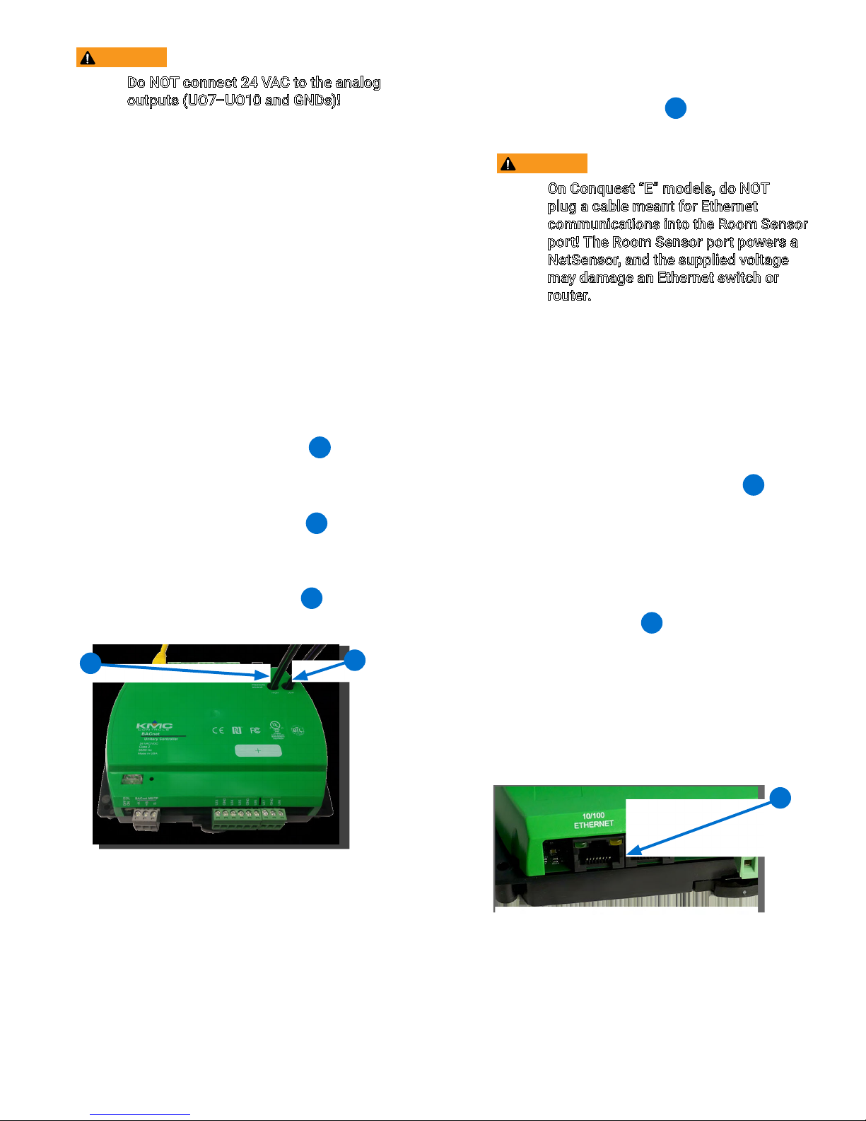
CAUTION
Do NOT connect 24 VAC to the analog
outputs (UO7–UO10 and GNDs)!
NOTE: Use 24 VAC (only) with triac outputs
(BO1–BO6 with SCs).
CONNECT (OPT.) PRESSURE FLOW SENSOR
NOTE: Complete the steps in this section to
connect an air flow sensor to the BAC9311/9311C/9311CE controller.
NOTE: BAC-9301/9301C/9301CE controllers
do not have PRESSURE SENSOR ports.
NOTE: Use 1/4 inch (6.35 mm) FR tubing.
Tubing should not be longer than 6 feet
(20 meters).
1. Remove the black shipping plugs
PRESSURE SENSOR ports.
2. Connect the high pressure tube from the
pressure flow sensor to the HIGH
the controller.
3. Connect the low pressure tube from the
pressure flow sensor to the LOW
the controller.
12
from the
9
12
port on
13
port on
13
CONNECT (OPT.) ETHERNET NETWORK
1. For BAC-93x1CE models (only), connect
14
an Ethernet patch cable
to the 10/100
ETHERNET port (“E” models only).
CAUTION
On Conquest “E” models, do NOT
plug a cable meant for Ethernet
communications into the Room Sensor
port! The Room Sensor port powers a
NetSensor, and the supplied voltage
may damage an Ethernet switch or
router.
NOTE: The Ethernet patch cable should be
T568B Category 5 or better and a
maximum of 328 feet (100 meters)
between devices.
NOTE: Before May 2016, BAC-xxxxCE models
had a single Ethernet port. They now
have dual Ethernet ports, enabling
daisy-chaining of controllers
the Daisy-Chaining Conquest Ethernet
Controllers Technical Bulletin on
the KMC Partner web site for more
information.
NOTE: On newer models, the Room Sensor
8
port is yellow
instead of black to
help differentiate it from the black
Ethernet ports.
14
. See
BAC-9300 Series Controller Installation Guide 3 925-019-02G
NOTE: For more information, see Sample
(BAC-9311) Wiring on page 7 and the
YouTube video KMC Conquest Wiring:
BAC-9300 Series Unitary Controllers.
14
Page 4

CONNECT (OPTIONAL) MS/TP NETWORK
CONNECT POWER
1. For BAC-93x1/93x1C models (only), connect
the BACnet network to the gray BACnet MS/
15
TP terminal block
15
.
NOTE: Use 18 gauge AWG shielded twisted
pair cable with maximum capacitance
of 51 picofarads per foot (0.3 meters)
for all network wiring (Belden cable
#82760 or equivalent).
A. Connect the –A terminals in parallel with
all other –A terminals on the network.
B. Connect the +B terminals in parallel with all
other +B terminals on the network.
NOTE: Follow all local regulations and wiring
codes.
1. Connect a 24 VAC, Class-2 transformer to the
black power terminal block of the controller.
A. Connect the neutral side of the transformer
17
to the controllers common terminal
⊥
B. Connect the AC phase side of the
transformer to the controllers phase
18
∼
terminal
17
.
18
.
C. Connect the shields of the cable together
at each device using a wire nut or the S
terminal in KMC BACnet controllers.
2. Connect the cable shield to a good earth
ground at one end only.
NOTE: For principles and good practices
when connecting an MS/TP network,
see Planning BACnet Networks
(Application Note AN0404A).
NOTE: The EOL switch is shipped from the
factory in the OFF position.
3. If the controller is at either end of a BACnet
MS/TP network (only one wire under the
16
terminals), turn the EOL switch
to ON.
NOTE: For more information, see Sample
(BAC-9311) Wiring on page 7 and the
YouTube video KMC Conquest Wiring:
BAC-9300 Series Unitary Controllers.
16
NOTE: Connect only one controller to each
transformer with 12—24 AWG copper
wire.
NOTE: Use either shielded connecting cables
or enclose all cables in conduit to
maintain RF emissions specications.
NOTE: For more information, see Sample
(BAC-9311) Wiring on page 7 and the
YouTube video KMC Conquest Wiring:
BAC-9300 Series Unitary Controllers.
POWER AND COMMUNICATION STATUS
The status LEDs indicate power connection and
network communication. The descriptions below
describe their activity during normal operation (at
least 5 to 20 seconds after power-up/initialization
or restart).
NOTE: If both the green READY LED and the
amber COMM LED remain OFF, check
the power and cable connections to the
controller.
BAC-9300 Series Controller Installation Guide 4 925-019-02G
Page 5

Green READY LED
19
After controller power-up or restart is complete,
the READY LED flashes steadily about once per
second, indicating normal operation.
19
21
22
Amber (BACnet MS/TP) COMM LED
During normal operation, the COMM LED
20
flickers as the controller receives and passes
the token over the BACnet MS/TP network.
When the network is not connected or
communicating properly, the COMM LED
flashes more slowly (about once a second).
20
Amber ETHERNET LED
The amber Ethernet LED flashes when the
22
controller is communicating with a 100BaseT
Ethernet network.
The amber Ethernet LED remains OFF when
the (powered) controller is communicating
with the network at only 10 Mbps (instead of
100 Mbps).
NOTE: If both the green and amber Ethernet
LEDs remain OFF, check the power and
network cable connections.
MS/TP NETWORK ISOLATION BULBS
The two network isolation bulbs 23 serve three
functions:
Removing the (HPO-0055) bulb assembly
opens the MS/TP circuit and isolates the
controller from the network.
Green ETHERNET LED
21
NOTE: The Ethernet status LEDs
indicate network connection and
communication speed.
The green Ethernet LED stays ON when the
controller is communicating with the network.
The green Ethernet LED is OFF when the
(powered) controller is not communicating
with the network.
If one or both bulbs are ON, the network is
improperly phased. This means the ground
potential of the controller is not the same
as other controllers on the network. If
this happens, x the wiring. See Connect
(Optional) MS/TP Network on page 4.
If the voltage or current on the network
exceeds safe levels, the bulbs blow, opening
the circuit. If this happens, x the problem and
replace the bulb assembly.
23
BAC-9300 Series Controller Installation Guide 5 925-019-02G
Page 6

CONFIGURE/PROGRAM THE CONTROLLER
See the table for the most relevant KMC Controls
tool for conguring, programming, and/or creating
graphics for the controller. See the documents or
Help systems for the respective KMC tool for more
information.
See the table (on the next page) for the most
relevant KMC Controls tools for conguring,
programming, and/or creating graphics for the
controller. See the tools’ documents or Help
systems for more information.
NOTE: After the controller has been
congured, an STE-6010/6014/6017
series analog sensor can be connected
to the controller in place of an STE9000 series digital NetSensor.
SETUP PROCESS
Cong-
uration
Programming
(Control Basic)
Web Page
Graphics*
**** ****
KMC
CONTROLS
TOOL
Conquest
NetSensor
Internal con-
guration web
pages in Conquest Ethernet
“E” models**
KMC Connect
Lite™ (NFC)
app***
KMC Connect™ software
TotalControl™
software
NOTE: A BAC-9301CE can be congured by
connecting an HTML5-compatible
web browser to the controller’s default
IP address (192.168.1.251). See
the Conquest Ethernet Controller
Conguration Web Pages Application
Guide for more information about the
built-in conguration web pages.
NOTE: To congure a VAV controller, enter
the correct K factor for the VAV
box. Typically, this is supplied by
the manufacturer of the VAV unit. If
this information is unavailable, use
an approximate K factor from the
chart in the Appendix: K Factors for
VAV section in the KMC Conquest
Controller Application Guide.
For instructions on VAV balancing:
With an STE-9000 series NetSensor, see
the VAV Airflow Balancing with an STE-9xx1
section of the KMC Conquest Controller
Application Guide.
KMC Con-
*Custom graphical user-interface web pages can be
hosted on a remote web server, but not in the
controller.
**Conquest Ethernet-enabled “E” models with the
latest rmware can be congured with an HTML5
compatible web browser from pages served from
within the controller. For information, see the Con
quest Ethernet Controller Conguration Web
Pages Application Guide.
***Near Field Communication via enabled smart
phone or tablet running the KMC Connect Lite app.
****Full conguration and programming of KMC
Conquest controllers is supported starting with
TotalControl ver. 4.0.
verge™ module
for Niagara
WorkBench
KMC Converge GFX
module for
Niagara WorkBench
With a BAC-5051E Router, see its application
and installation guide.
With KMC Connect or TotalControl, see the
Help system for the software.
BAC-9300 Series Controller Installation Guide 6 925-019-02G
Page 7

SAMPLE (BAC-9311) WIRING
(Single Duct VAV, Series Fan Powered with Modulating Reheat and Vent Control)
NOTE: Connect the STE-9xxx (or
STE-6010/6014/6017 with
no ventilation control) sensor
to the Room Sensor port
using a max. of 150 feet
of Ethernet patch cable.
NOTE: See the KMC Conquest Controller
Application Guide for information
about switched commons (SC),
using VDC power, and other issues.
NOTE: Use 24 VAC (only) on triac
outputs (BO1–BO6 with SCs)!
CAUTION: Do NOT connect 24 VAC
to the analog outputs
(UO7–UO10 and GNDs)!
CONNECTIONS (SAMPLE)
INPUTS
UI3 = DAT SENSOR
UI8 = PRI POSITION
ROOM SENSOR
OUTPUTS (Binary/Triac)
BO1 = FAN ENABLE
BO5 = PRI DAMPER CW
BO6 = PRI DAMPER CCW
OUTPUTS (Universal/Analog)
UO7 = MOD REHEAT
UO8 = FAN SPEED
NETWORK
MS/TP OR ETHERNET
POWER
STE-9521
STE-6010-10
BAC-9311 Controller
SENSOR
ROOM
Fan
Start
~
BO1
COM
BO2
MEP-4001/
CW P1
SC
BO5
BO3
BO4
Damper
Primary
Actuator
SC
BO6
MEP-4013
P2CCW COM
UO7
UO8
GND
UO9
GND
PRESSURE
SENSOR
Mod
Reheat
+
UO10
–
–
–
~
24 VAC/VDC
HIGH LOW
H
to flow sensor
Fan
Voltage
Speed
+
–
–
24 VAC
L
1/4" (6.35) FR tubing
Line
HN
~
PhaseNeutral
NOTE: For MS/TP models, turn the End Of
Line switch ON at both physical ends
of the MS/TP network. Connect the
cable shield to earth ground at only
one point.
NOTE: For Ethernet models, connect the
controller to the network with a
standard Ethernet patch cord.
NOTE: For more wiring examples, see the
wiring diagrams that are part of the
application library in KMC Connect,
Converge, or TotalControl. Early
models shown in the drawings had
different terminal locations. Follow
the terminal labels (not location).
BAC-9300 Series Controller Installation Guide 7 925-019-02G
RED
BLK
From
Previous
Controller
SHLD
EOL
ON
OFF
SHLD
RED
BLK
To
Next
Controller
MS/TP
-A
10/100
ETHERNET
S
+B
UI3
GND
UI4
UI5
GND
UI6
UI7
GND
UI8
(From Optional MEP-4x13 10K
Ohm Feedback Potentiometer)
NOTE: Analog inputs accept 1K or 10K
sensors, 0–12 VDC, or 4–20 mA.
(Optional)
STE-1405
To
Ethernet
DISCHARGE AIR TEMP
10KΩ, TYPE 3 Thermistor
Page 8

INPUT/OUTPUT OBJECTS/CONNECTIONS
BAC-9301 FCU (2-PIPE) BAC-9301 FCU (4-PIPE)
Inputs Inputs
AI1 Space Sensor (on Room Sensor port) AI1 Space Sensor (on Room Sensor port)
AI2 Space Setpoint Offset (on port) AI2 Space Setpoint Offset (on port)
AI3/UI3 Discharge Air Temperature AI3/UI3 Discharge Air Temperature
AI4/UI4 Outdoor Air Temp AI4/UI4 Outdoor Air Temp
AI5/UI5 Space Humidity AI5/UI5 Space Humidity
AI6/UI6 Supply Water Temperature AI7/UI7 Analog Input #7
AI8/UI8 Analog Input #8 AI8/UI8 Analog Input #8
BI7/UI7 Fan BI6/UI6 Fan
Outputs Outputs
AO7/UO7 Analog Heat/Cool Valve (Proportional)* AO7/UO7 Analog Cooling Valve (Proportional)*
AO8/UO8 Auxiliary Heat (Proportional)** AO8/UO8 Analog Heating Valve (Proportional)**
AO9/UO9 Analog Output #9 AO9/UO9 Analog Output #9
AO10/UO10 Fan Speed Control AO10/UO10 Fan Speed Control
BO1 Fan Low Speed BO1 Fan Low Speed
BO2 Fan Medium Speed BO2 Fan Medium Speed
BO3 Fan High Speed BO3 Fan High Speed
BO4 Binary Heat/Cool Valve (On/Off)* BO4 Binary Cooling Valve (On/Off)*
BO5 Auxiliary Heat (On/Off)** BO5 Binary Heating Valve (On/Off)**
BO6 Binary Output #6 BO6 Binary Output #6
*AO7 and BO4 are controlled simultaneously.
**AO8 and BO5 are controlled simultaneously.
*AO7 and BO4 are controlled simultaneously.
**AO8 and BO5 are controlled simultaneously.
BAC-9301 HPU BAC-9311 HPU
Inputs Inputs
AI1 Space Sensor (on Room Sensor port) AI1 Space Sensor (on Room Sensor port)
AI2 Space Setpoint Offset (on port) AI2 Space Setpoint Offset (on port)
AI3/UI3 Discharge Air Temperature AI3/UI3 Discharge Air Temperature
AI4/UI4 Outdoor Air Temp AI4/UI4 Outdoor Air Temp
AI5/UI5 Space Humidity AI5/UI5 Space Humidity
AI7/UI7 Analog Input #7 AI7/UI7 Analog Input #7
AI8/UI8 Analog Input #8 AI8/UI8 Analog Input #8
BI6/UI6 Fan AI9 Duct Pressure (internal sensor)
BI6/UI6 Fan
Outputs Outputs
AO7/UO7 Analog Output #7 AO7/UO7 Analog Output #7
AO8/UO8 Analog Output #8 AO8/UO8 Analog Output #8
AO9/UO9 Economizer Output AO9/UO9 Economizer Output
AO10/UO10 Analog Output #10 AO10/UO10 Analog Output #10
BO1 Fan Start - Stop BO1 Fan Start - Stop
BO2 Stage 1 Compressor BO2 Stage 1 Compressor
BO3 Stage 2 Compressor BO3 Stage 2 Compressor
BO4 Reversing Valve BO4 Reversing Valve
BO5 Auxiliary Heat BO5 Auxiliary Heat
BO6 Binary Output #6 BO6 Binary Output #6
BAC-9300 Series Controller Installation Guide 8 925-019-02G
Page 9

BAC-9301 RTU BAC-9311 RTU
Inputs Inputs
AI1 Space Sensor (on Room Sensor port) AI1 Space Sensor (on Room Sensor port)
AI2 Space Setpoint Offset (on port) AI2 Space Setpoint Offset (on port)
AI3/UI3 Discharge Air Temperature AI3/UI3 Discharge Air Temperature
AI4/UI4 Outdoor Air Temp AI4/UI4 Outdoor Air Temp
AI5/UI5 Space Humidity AI5/UI5 Space Humidity
AI7/UI7 Analog Input #7 AI7/UI7 Economizer Feedback
AI8/UI8 Analog Input #8 AI8/UI8 Analog Input #8
BI6/UI6 Fan AI9 Duct Pressure (internal sensor)
BI6/UI6 Fan
Outputs Outputs
AO7/UO7 Analog Cooling Output AO7/UO7 Analog Cooling Output
AO8/UO8 Analog Heating Output AO8/UO8 Analog Heating Output
AO9/UO9 Economizer Output AO9/UO9 Economizer Output
AO10/UO10 Analog Output #10 AO10/UO10 Analog Output #10
BO1 Fan Start - Stop BO1 Fan Start - Stop
BO2 Cool Stage 1 BO2 Cool Stage 1
BO3 Cool Stage 2 BO3 Cool Stage 2
BO4 Binary Output #4 BO4 Binary Output #4
BO5 Heating Stage 1 BO5 Heating Stage 1
BO6 Heating Stage 2 BO6 Heating Stage 2
BAC-9311 VAV
Inputs
AI1 Space Sensor (on Room Sensor port)
AI2 Space Setpoint Offset (on port)
AI3/UI3 Discharge Air Temperature
AI4/UI4 Analog Input #4
AI5/UI5 Analog Input #5
AI6/UI6 Analog Input #6
AI7/UI7 Analog Input #7
AI8/UI8 Primary Damper Position
AI9 Primary Duct Pressure (internal sensor)
Outputs
AO7/UO7 Analog Heat
AO8/UO8 Fan Speed
AO9/UO9 Analog Output #9
AO10/UO10 Analog Output #10
BO1 Fan
BO2 Heating Stage 1
BO3 Heating Stage 2
BO4 Heating Stage3
BO5 Primary Damper CW
BO6 Primary Damper CCW
NOTE: See Sample (BAC-9311) Wiring on
page 7 for more information.
NOTE: Universal Input (UIx) terminal = Analog
Input (AIx) object or Binary Input (BIx).
Universal Output (UOx) terminal =
Analog Output (AOx) object.
NOTE: Universal (analog) inputs and outputs
can be congured to emulate binary
(on/off or voltage/no-voltage) objects.
They are used with GND terminals.
NOTE: Binary Output (BOx) terminals are
triacs and are used with SC terminals
instead of GND terminals.
BAC-9300 Series Controller Installation Guide 9 925-019-02G
Page 10

REPLACEMENT PARTS
IMPORTANT NOTICES
HPO-0055 Replacement Network
Bulb Module for Conquest
Controllers, Pack of 5
HPO-9901 Conquest Hardware
Replacement Parts Kit
NOTE: HPO-9901 includes the following:
Terminal Blocks DIN Clips
(1) Black 2 Position (2) Small
(2) Grey 3 Position (1) Large
(2) Green 3 Position
(4) Green 4 Position
(2) Green 5 Position
(2) Green 6 Position
NOTE: See the Conquest Selection Guide for
more information about replacement
parts and accessories.
The material in this document is for information
purposes only. The contents and the product it
describes are subject to change without notice.
KMC Controls, Inc. makes no representations or
warranties with respect to this document. In no
event shall KMC Controls, Inc. be liable for any
damages, direct, or incidental, arising out of or
related to the use of this document.
The KMC logo is a registered trademark of KMC
Controls, Inc. All rights reserved.
TEL: 574.831.5250
FAX: 574.831.5252
EMAIL: info@kmccontrols.com
© 2019 KMC Controls, Inc. Specifications and design subject to change without notice 925-019-02G
BAC-9300 Series Controller Installation Guide 10 925-019-02G
 Loading...