

Page 1
BAC-9000 Series VAV Controller
Installation Guide
CONTENTS
Introduction .............................................. 1
Set Drive Hub (45/60°) Rotation Limit ............ 1
Mount Controller ........................................ 2
Connect Sensors and Equipment .................. 3
Connect (Optional) Pressure Sensor.............. 4
Connect (Opt.) Ethernet Network .................. 4
Connect (Optional) MS/TP Network............... 5
Connect Power .......................................... 5
Power and Communication Status ................. 6
MS/TP Network Isolation Bulbs .................... 6
Watch Dog Jumper ..................................... 7
Congure/Program the Controller ................. 7
Sample (BAC-9001) Wiring .......................... 8
Replacement Parts ..................................... 9
Important Notices ...................................... 9
INTRODUCTION
2
NOTE: The V-clamp nuts 3 should be on top.
3
1
Complete the following steps to install a KMC
Conquest™ BAC-9000 Series VAV Controller-
Actuator. For controller specications, see the
data sheet at kmccontrols.com. For additional
information, see the KMC Conquest Controller
Application Guide.
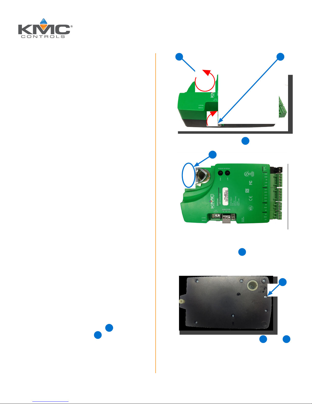
SET DRIVE HUB (45/60°) ROTATION LIMIT
NOTE: Complete the steps in this section if
the VAV damper rotation limit is either
60 or 45 degrees.
NOTE: If the VAV damper rotates 90 degrees,
skip this section and go to Mount
Controller on page 2 instead.
1. Push and hold the gear release
the drive hub and V-clamp
2
and rotate
1
to the left.
2. Turn the controller over.
3. Remove the stop screw
location and clean any debris from the
threads.
4. Insert the stop screw into the 60 5 or 45 6
stop hole position.
from the storage
4
4
KMC Controls, 19476 Industrial Drive, New Paris, IN 46553 / 877.444.5622 / Fax: 574.831.5252 / www.kmccontrols.com
Page 2
5
NOTE: The drive hub and V-clamp will be
rotated in the same direction in Step 8.
2. Push and hold the gear disengagement
lever
on the side of the controller.
8
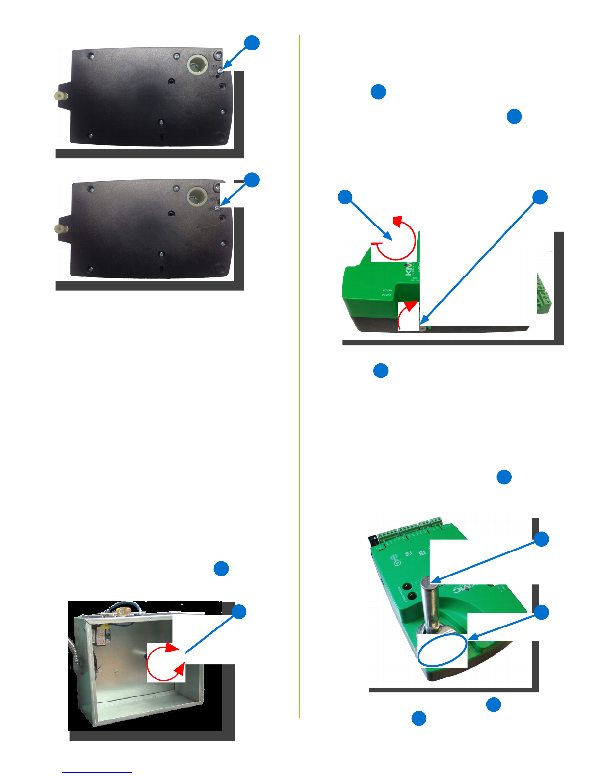
5. Tighten the screw until the screw head
touches the plastic in the bottom of the recess.
NOTE: Overtightening the screw can cause
compression in the case which may
interfere with the controller operation.
3. Rotate the drive hub and V-clamp
in the
9
same direction that opened the damper.
NOTE: Continue to rotate the drive hub and
V-clamp until they reach a stop.
6
9
8
4. Position the controller over the damper
10
shaft
blocks are easy to access for wiring
so that the color-coded terminal
.
MOUNT CONTROLLER
NOTE: Install the controller in a metal
enclosure for RF shielding and physical
protection.
NOTE: The controller can be installed on a
3/8–5/8 inch (9.5–16 mm) round or
3/8–7/16 inch (99.5–11 mm) square
damper shaft with a minimum length
of 2 inches (51 mm).
1. Manually rotate the damper shaft
VAV box to fully open the damper.
on the
7
NOTE: The black terminals are for power.
The green terminals are for inputs and
outputs. The gray terminals (if present)
are for MS/TP communication.
11
5. Finger-tighten the V-clamp nuts
to position
the damper shaft in the drive hub.
10
7
11
BAC-9000 Series Controller Installation Guide 2 921-019-01F
6. Center the mounting bushing 12 in the
13
mounting tab
.
Page 3
12
13
7. Attach the controller to the VAV box with a
#8 sheet metal screw through the mounting
12
bushing
8. Evenly tighten the V-clamp nuts
.
11
on the
drive hub to 30–35 in-lb.
14
NOTE: The Ethernet patch cable should be a
maximum of 150 feet (45 meters).
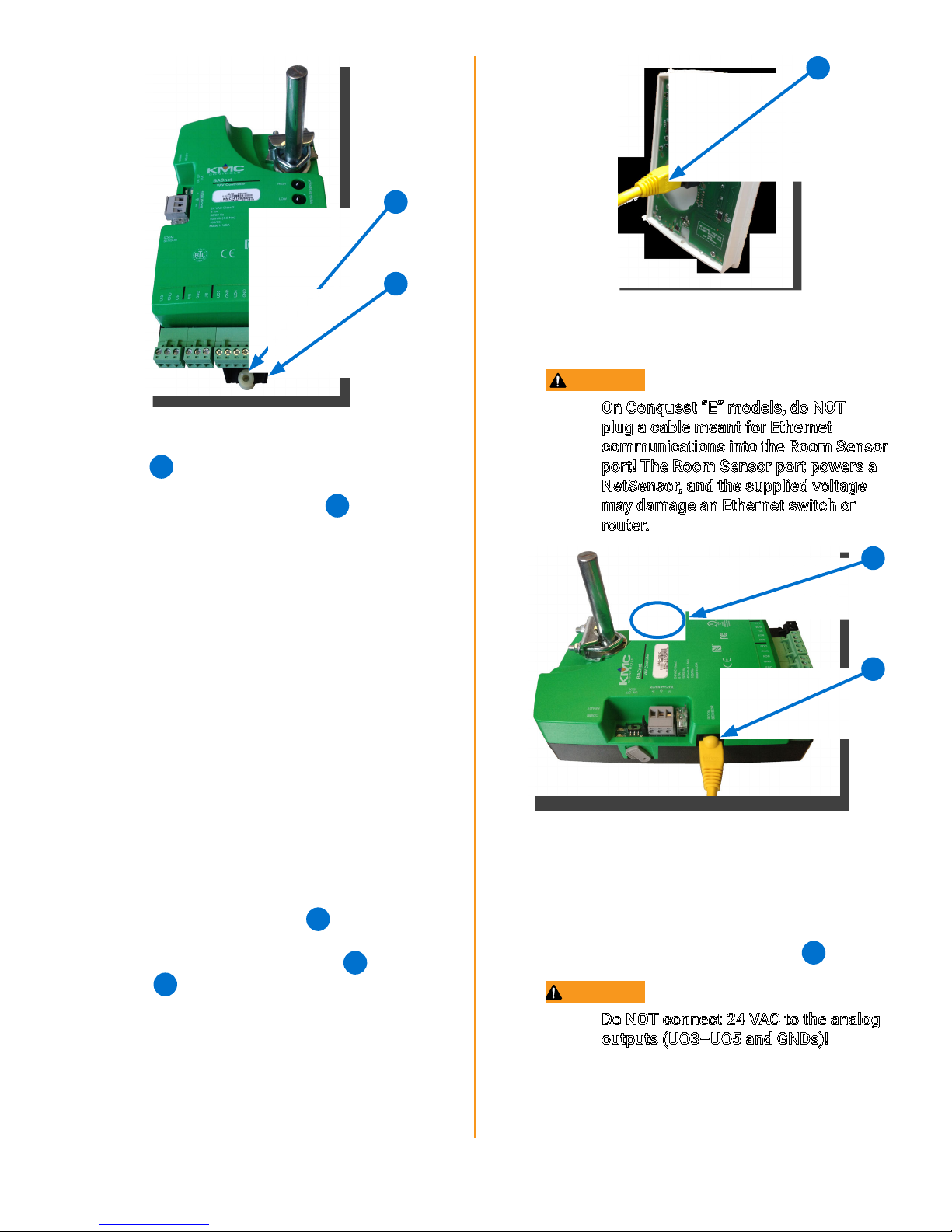
CAUTION
On Conquest “E” models, do NOT
plug a cable meant for Ethernet
communications into the Room Sensor
port! The Room Sensor port powers a
NetSensor, and the supplied voltage
may damage an Ethernet switch or
router.
CONNECT SENSORS AND EQUIPMENT
NOTE: A digital STE-9000 Series NetSensor
can be used for conguring the
controller (see Congure/Program
the Controller on page 7). After the
controller has been congured, an
STE-6010, STE-6014, or STE-6017
analog sensor can be connected to the
controller in place of the NetSensor.
See the relevant installation guide for
additional details.
NOTE: See Sample (BAC-9001) Wiring on
page 8 for more information.
14
1. Plug an Ethernet patch cable
to an STE-9xxx or STE-6010/6014/6017
sensor into the controller’s (yellow
15
SENSOR
port.
connected
22
) ROOM
16
15
NOTE: Auxiliary VAV equipment such as fans,
heaters, reheat valves, and discharge
air temperature sensors can be
connected to the controller.
2. Connect auxiliary VAV equipment to the input
17
and output green terminal blocks
.
CAUTION
Do NOT connect 24 VAC to the analog
outputs (UO3–UO5 and GNDs)!
BAC-9000 Series Controller Installation Guide 3 921-019-01F
NOTE: Use 24 VAC (only) with triac outputs
(BO6–BO9 with SC).
NOTE: Wire sizes 12–24 AWG can be clamped
in each terminal.
Page 4

NOTE: No more than two (16 AWG) wires can
be joined at a common point.
17
CONNECT (OPTIONAL) PRESSURE SENSOR
NOTE: Complete the steps in this section
to connect an air flow sensor to the
controller.
NOTE: Only the BAC-9021 controller does not
have PRESSURE SENSOR ports. For
that model, skip this section.
18 19
CONNECT (OPT.) ETHERNET NETWORK
1. For a BAC-9001CE (only), connect an Ethernet
20
patch cable
to the 10/100 ETHERNET
port.
CAUTION
On Conquest “E” models, do NOT
plug a cable meant for Ethernet
communications into the Room Sensor
port! The Room Sensor port powers a
NetSensor, and the supplied voltage
may damage an Ethernet switch or
router.
NOTE: Use 1/4 inch (6.35 mm) FR tubing.
Tubing should not be longer than 20
feet (6 meters).
16
1. Remove the black shipping plugs
from the
PRESSURE SENSOR ports.
2. Connect the high pressure tube from the
18
pressure flow sensor to the HIGH
port on
the controller.
3. Connect the low pressure tube from the
19
pressure flow sensor to the LOW
port on
the controller.
NOTE: Before May 2016, BAC-9001CE models
20
had a single Ethernet port
now have dual Ethernet ports
. They
21
,
enabling daisy-chaining of controllers.
See the Daisy-Chaining Conquest
Ethernet Controllers Technical
Bulletin on the KMC Partner web site
for more information.
20
BAC-9000 Series Controller Installation Guide 4 921-019-01F
Page 5

NOTE: Also on the newer models, the Room
22
Sensor port is yellow
instead of
black to help differentiate it from the
black Ethernet ports.
22 21
NOTE: The Ethernet patch cable should be
T568B Category 5 (or better) and a
maximum of 328 feet (100 meters)
between devices.
see Planning BACnet Networks
(Application Note AN0404A).
NOTE: The EOL switch is shipped from the
factory in the OFF position.
3. If the controller is at either end of a BACnet
MS/TP network (only one wire under each
24
terminal), turn the EOL switch
to ON.
24
CONNECT (OPTIONAL) MS/TP NETWORK
1. For a BAC-9001 or BAC-9021, connect the
network to the gray BACnet MS/TP network
23
terminal block
NOTE: Use 18 gauge AWG shielded twisted
pair cable with maximum capacitance
of 51 picofarads per foot (0.3 meters)
for all network wiring (Belden cable
#82760 or equivalent).
A. Connect the –A terminals in parallel with
all other –A terminals on the network.
B. Connect the +B terminals in parallel with all
other +B terminals on the network.
.
23
CONNECT POWER
NOTE: Follow all local regulations and wiring
codes.
1. Connect a 24 VAC, Class-2 transformer to
25
the black power terminal block
of the
controller.
A. Connect the neutral side of the transformer
to the controller’s common terminal
⊥
B. Connect the AC phase side of the
transformer to the controller’s phase
27
∼
terminal
26
27
.
25
26
.
C. Connect the shields of the cable together
at each device using a wire nut or the S
terminal in KMC BACnet controllers.
2. Connect the cable shield to a good earth
ground at one end only.
NOTE: For principles and good practices
when connecting an MS/TP network,
BAC-9000 Series Controller Installation Guide 5 921-019-01F
NOTE: Connect only one controller to each
transformer with 12–24 AWG copper
wire.
NOTE: Use either shielded connecting cables
or enclose all cables in conduit to
maintain RF emissions specications.
Page 6

POWER AND COMMUNICATION STATUS
The status LEDs indicate power connection and
network communication. The descriptions below
describe their activity during normal operation (at
least 5 to 20 seconds after power-up/initialization
or restart).
NOTE: If both the green READY LED and the
amber COMM LED remain OFF, check
the power and cable connections to the
controller.
Green READY LED
After controller power-up or restart is complete,
the READY LED flashes steadily about once per
second, indicating normal operation.
Amber (BACnet MS/TP) COMM LED
28
29
30 31
Amber ETHERNET LED
The amber Ethernet LED flashes when the
31
controller is communicating with a 100BaseT
Ethernet network.
The amber Ethernet LED remains OFF when
the (powered) controller is communicating
with the network at only 10 Mbps (instead of
100 Mbps).
During normal operation, the COMM LED
flickers as the controller receives and passes
the token over the BACnet MS/TP network.
When the network is not connected or
communicating properly, the COMM LED
flashes more slowly (about once a second).
Green ETHERNET LED
30
NOTE: The Ethernet status LEDs
indicate network connection and
communication speed.
The green Ethernet LED stays ON when the
controller is communicating with the network.
The green Ethernet LED is OFF when the
(powered) controller is not communicating
with the network.
29
28
NOTE: If both the green and amber Ethernet
LEDs remain OFF, check the power and
network cable connections.
MS/TP NETWORK ISOLATION BULBS
32
The two network isolation bulbs 32 serve three
functions:
Removing the (HPO-0055) bulb assembly
opens the MS/TP circuit and isolates the
controller from the network.
If one or both bulbs are ON, the network is
improperly phased. This means the ground
potential of the controller is not the same
as other controllers on the network. If
this happens, x the wiring. See Connect
(Optional) MS/TP Network on page 5.
If the voltage or current on the network
exceeds safe levels, the bulbs blow, opening
the circuit. If this happens, x the problem and
replace the bulb assembly.
BAC-9000 Series Controller Installation Guide 6 921-019-01F
Page 7

WATCH DOG JUMPER
The watch dog jumper 33 resets the controller
if there is a power failure or a communication
timeout between the controller and the network.
Never remove the jumper (from the two outer
pins).
33
Cong-
uration
SETUP PROCESS
Programming
(Control Basic)
Web Page
Graphics*
KMC
CONTROLS
TOOL
Conquest
NetSensor
Internal con-
guration web
pages in Conquest Ethernet
“E” models**
KMC Connect
Lite™ (NFC)
app***
CONFIGURE/PROGRAM THE CONTROLLER
See the table (on the next page) for the most
relevant KMC Controls tools for conguring,
programming, and/or creating graphics for the
controller. See the tools’ documents or Help
systems for more information.
NOTE: After the controller has been
congured, an STE-6010/6014/6017
series analog sensor can be connected
to the controller in place of an STE-
9000 series digital NetSensor.
NOTE: A BAC-9001CE can be congured by
connecting an HTML5-compatible
web browser to the controller’s default
IP address (192.168.1.251). See
the Conquest Ethernet Controller
Conguration Web Pages Application
Guide for more information about the
built-in conguration web pages.
**** ****
*Custom graphical user-interface web pages can be
hosted on a remote web server, but not in the
controller.
**Conquest Ethernet-enabled “E” models with the
latest rmware can be congured with an HTML5
compatible web browser from pages served from
within the controller. For information, see the Con
quest Ethernet Controller Conguration Web
Pages Application Guide.
***Near Field Communication via enabled smart
phone or tablet running the KMC Connect Lite app.
****Full conguration and programming of KMC
Conquest controllers is supported starting with
TotalControl ver. 4.0.
KMC Connect™ software
TotalControl™
software
KMC Converge™ module
for Niagara
WorkBench
KMC Converge GFX
module for
Niagara WorkBench
BAC-9000 Series Controller Installation Guide 7 921-019-01F
Page 8

SAMPLE (BAC-9001) WIRING
(Single Duct VAV, Series Fan Powered with Floating Reheat and Vent Control)
BAC-9001/9001CE Controller
NOTE: For MS/TP models, turn the
End Of Line switch ON at both
physical ends of the MS/TP
network. Connect the cable
shield to earth ground at only
one point.
Controller
Previous
From
Controller
Next
To
STE-9521
STE-6010-10
RED
BLK
SHLD
RED
BLK
SHLD
To
Ethernet
RDY
COM
ROOM
SENSOR
10/100
ETHERNET
UI3
+B
GND
OFFON
-A
S
UI4
EOL
BACnet MS/TP
UI5
GND
UI6
UO3
GND
UO4
GND
UO5
HIGH
LOW
BO6
BO7SCBO8
BO9
~
L
1/4" (6.35) FR tubing
to flow sensor
H
PRESSURE SENSOR
H N
~
Phase
NOTE: For more wiring examples, see the
wiring diagrams that are part of the
application library in KMC Connect,
Converge, or TotalControl.
CONNECTIONS (SAMPLE)
INPUTS
UI3 = DAT SENSOR
ROOM SENSOR
OUTPUTS (Binary/Triac)
BO6 = FAN ENABLE
BO7 = OPEN VALVE
BO8 = CLOSE VALVE
OUTPUTS (Universal/Analog)
UO4 = FAN SPEED
NETWORK
MS/TP OR ETHERNET
Line
Voltage
24 VAC
(Only)
–
Neutral
POWER
Floating
Reheat
OPEN CLOSECOM
COM
Fan
Start
~
NOTE: Connect the STE-9xxx (or
STE-6010/6014/6017 with
no ventilation control) sensor
to the Room Sensor port
using a max. of 150 feet
of Ethernet patch cable.
NOTE: For Ethernet models, connect the
controller to the network with a
standard Ethernet patch cord.
NOTE: Analog inputs accept 1K or 10K
sensors, 0–12 VDC, or 4–20 mA.
BAC-9000 Series Controller Installation Guide 8 921-019-01F
(Optional)
DAT
STE-1405
10K Ohm
Type 3
Thermistor
NOTE: Use 24 VAC (only) on triac outputs
(BO6–BO9 with SC)!
CAUTION: Do NOT connect 24 VAC to the
analog outputs (UO3–UO5 and GNDs)!
Fan
Speed
–
+
Page 9

REPLACEMENT PARTS
IMPORTANT NOTICES
HPO-0055 Replacement Network
Bulb Module for Conquest
Controllers, Pack of 5
HPO-9901 Conquest Hardware
Replacement Parts Kit
NOTE: HPO-9901 includes the following:
Terminal Blocks DIN Clips
(1) Black 2 Position (2) Small
(2) Grey 3 Position (1) Large
(2) Green 3 Position
(4) Green 4 Position
(2) Green 5 Position
(2) Green 6 Position
NOTE: See the Conquest Selection Guide for
more information about replacement
parts and accessories.
The material in this document is for information
purposes only. The contents and the product it
describes are subject to change without notice.
KMC Controls, Inc. makes no representations or
warranties with respect to this document. In no
event shall KMC Controls, Inc. be liable for any
damages, direct, or incidental, arising out of or
related to the use of this document.
The KMC logo is a registered trademark of KMC
Controls, Inc. All rights reserved.
TEL: 574.831.5250
FAX: 574.831.5252
EMAIL: info@kmccontrols.com
© 2017 KMC Controls, Inc. Specifications and design subject to change without notice 921-019-01F
 Loading...