

Page 1

SimplyVAV
Application and Installation Guide
Revision E
Page 2

SimplyVAV
©2014, KMC Controls, Inc.
SimplyVAV and the SimplyVAV logo are trademarks of KMC Controls, Inc.
All rights reserved. No part of this publication may be reproduced,
transmitted, transcribed, stored in a retrieval system, or translated into any
language in any form by any means without the written permission of KMC
Controls, Inc.
Printed in U.S.A.
The material in this manual is for information purposes only. The contents
and the product it describes are subject to change without notice. KMC
Controls, Inc. makes no representations or warranties with respect to this
manual. In no event shall KMC Controls, Inc. be liable for any damages, direct
or incidental, arising out of or related to the use of this manual.
KMC Controls, Inc.
19476 Industrial Drive
New Paris, IN 46553
U.S.A.
TEL: 1.574.831.5250
FAX: 1.574.831.5252
E-mail: info@kmccontrols.com
2 Revision E
Page 3

SimplyVAV
C o n t e n t s
Contents 3
Section 1: About the controllers 5
Specifications
Accessories and replacement parts
Available models
Safety considerations
11
12
13
Section 2: Installing the controllers 15
Setting the rotation limits
Mounting on a VAV terminal box
Connecting an airflow sensor
Connecting inputs and outputs
Connecting room temperature sensors
Connecting a DAT sensor
Connecting power
Maintenance
16
17
18
18
19
20
21
22
7
Section 3: Changing the room setpoint 23
Section 4: Configuring the controllers 25
Getting started with configuration
Entering system temperature setpoints and limits
Configuring the VAV Box options
Set the airflow setpoints
Advanced options
Restore Application
26
27
31
34
37
40
Section 5: Balancing airflow 43
Section 6: Application drawings 49
Cooling or heating without reheat
Staged reheat
Modulating reheat
Time proportional reheat
Floating reheat
Dual-duct application
50
51
52
53
54
55
Section 7: Sequences of operation 57
Input sources
Occupancy sequence
Automatic occupancy
Occupied
Unoccupied
58
59
59
59
59
Revision E 3
Page 4

SimplyVAV
Standby
Space setpoints
Types of setpoints
Setpoint limits
PID control loops
Airflow setpoints sequence
Changeover
Discharge Air Temperature (DAT) limiting
System diagnostics
Damper operation
Fan operation
Series Fan
ParallelFan
Reheat sequence
Modulating reheat
Staged reheat
Time proportioned reheat
Floating reheat
Balancing airflow sequence
Dual duct
59
60
60
61
61
61
62
62
64
65
65
65
66
66
66
67
67
68
69
69
Section 8: System integration and networking 71
Connecting to an MS/TP network
Connections and wiring
End of line termination switches
Network bulbs
Setting up network communications
BACnet objects
Input objects
Output objects
Value objects
Loop objects
72
72
73
73
75
77
77
77
78
80
Appendix A: K-factors 83
Index 85
4 Revision E
Page 5

SimplyVAV
S e c t i o n 1 : A b o u t th e c o n t r o ll e r s
This section provides a description of the SimplyVAV series of
controllers. It also introduces safety information. Review this material
before selecting, installing, or operating the controllers.
The SimplyVAV series of controllers are an easy and unique approach to
operating a wide variety of VAV terminal units. The integrated actuators,
internal airflow sensors, and wide variety of application programs make these
BACnet Application Specific controllers ideal for either new or retrofit
installations.
The controllers feature simple, menu driven setup choices when used with a
SimplyVAV digital sensor. No special programming skills or software tools
are required to choose applications, enter setpoints, set network addressing,
and balance airflow. All options can be set by using only an STE-8001 sensor
which can be installed as the permanent room sensor or temporarily
connected as a technician’s service tool.
All models are BACnet Application Specific Controllers that are ready to
connect to a BACnet MS/TP network. Device instance, MAC address, and
baud rate are set from an STE-8001 without special software.
BAC-8001
of operation for the following functions.
Model BAC-8001 is supplied with inputs, outputs, and sequences
Single duct heating and cooling VAV
Automatic heating/cooling changeover including morning warmup
Occupancy setback—requires STE-8201
System diagnostic indicators
Airflow balancing
Revision E 5
Page 6

Section 1: About the controllers SimplyVAV
BAC-8005 and BAC-8205
inputs, outputs, and sequences of operation for the following functions.
Single duct heating and cooling VAV
Modulating, floating, time proportional, and staged reheat
Series and parallel fan control
Automatic heating/cooling changeover including morning warmup
Discharge air temperature limiting
Occupancy setback—requires STE-8201
Actuator position feedback for true damper positioning (BAC-8205 only)
System diagnostic indicators
Airflow balancing
BAC-8007
of operation for the following functions.
Model BAC-8007 is supplied with inputs, outputs, and sequences
Dual-duct VAV heating and cooling
Occupancy setback—requires STE-8201
System diagnostic indicators
Airflow balancing
Models BAC-8005 and BAC-8205 are supplied with
Additional topics in this section
Specifications
Accessories and replacement parts
Available models
Safety considerations
7
11
12
13
6 Revision E
Page 7

SimplyVAV Section 1: About the controllers
Specifications
SimplyVAV specifications are subject to change without notice.
Inputs and outputs
All inputs and outputs are factory programmed and application specific. No
field configuration is required. For details on input and output connections,
see the topic Application drawings on page 49. For a detailed listing of input
and output objects, see the topic BACnet objects on page 77.
Analog inputs
Analog inputs represent BACnet analog input. Not all input are
applicable or required for all models.
Key features Standard units of measure.
Overvoltage input protection
Connectors RJ-45 room sensor jack
Screw terminals for wire sizes 12-26 AWG
Conversion 12–bit analog–to–digital conversion
Input range Passive, 10 kΩ pull-up to 3.3 volts DC
Analog outputs
Analog outputs are configured to represent BACnet analog output
objects. No field configuration is required. For details on application
specific output connections see the section Application drawings on page
49.
Key features Output short protection
Standard units of measure
Connector Screw terminals for wire size 12-26AWG
Conversion 12–bit digital-to-analog conversion
Output voltage 0–10 VDC
Output current 30 mA per output, 30 mA total for all analog
outputs
Binary outputs
Binary outputs are configured to represent BACnet binary output
objects. No field configuration is required. For details on application
specific output connections see the section Application drawings on page
49.
Key features Optically isolated triac output
Revision E 7
Page 8

Section 1: About the controllers SimplyVAV
Connector Screw terminals for wire size 12-26 AWG
Output range Maximum switching 24 Volts AC
1 ampere per external output, 3 amperes total
Communications—BACnet MS/TP
EIA–485 operating at rates up to 76.8 kilobaud.
Removable screw terminal block.
Wire size 12-26AWG
Switch selected end of line termination
Memory
Programs and program parameters are stored in nonvolatile memory.
Auto restart on power failure
Air flow sensor features
Configured as BACnet analog input object.
CMOS differential pressure 0-2 inches of water (0-500 Pa) measurement
range. Internally linearized and temperature compensated.
Span accuracy 4.5% of reading.
Zero point accuracy 0.0008 in. H2O/0.2 Pa at 25° C
Barbed connections for 1/4 inch FR tubing.
Actuator specifications
Torque 40 in-lb. (4.5 N•m)
Angular rotation 0 to 95°
Adjustable end stops at 45° and 60° rotation
Motor timing
BAC-8001,
BAC-8005, BAC-8007
Motor timing
BAC-8205
Shaft size Directly mounts on 3/8 to 5/8inch (9.5to16mm)
90 sec./90° at 60 Hz
108 sec./90° at 50 Hz
60 sec./90° at 60 Hz
round or 3/8 to 7/16 inch (9.5to11 mm) square
damper shafts.
8 Revision E
Page 9

SimplyVAV Section 1: About the controllers
Regulatory
UL 916 Energy Management Equipment
BACnet Testing Laboratory listed as an application specific controller
(ASC).
CE compliant
SASO PCP Registration KSA R-103263
FCC Class B, Part 15, Subpart B and complies with Canadian ICES-003
Class B
This device complies with part 15 of the FCC Rules. Operation is subject
to the following two conditions: (1) This device may not cause harmful
interference, and (2) this device must accept any interference received,
including interference that may cause undesired operation.
Installation
Supply voltage 24 volts AC, -15%, +20% 5 VA,
Weight 13.2 ounces (376 grams)
50/60 Hz
Case material Flame retardant plastic
Environmental limits
Operating 32 to 120° F (0 to 49° C)
Shipping –40 to 140° F (–40 to 60° C)
Humidity 5–93% relative humidity (non-condensing)
Revision E 9
Page 10

ON CTS
1 2
1.92 in.
49 mm
6.53 in.
166 mm
4.89 in.
124 mm
4.25 in.
108 mm
0.77 in.
19 mm
6.00 in.
152 mm
2.14 in.
54 mm
Section 1: About the controllers SimplyVAV
Dimensions
10 Revision E
Page 11

SimplyVAV Section 1: About the controllers
Accessories and replacement parts
The following accessories and replacement parts are available from KMC
Controls, Inc.
Sensors
STE-8001W80 SimplyVAV sensor and digital display
STE-8201W80 SimplyVAV sensor and digital display with motion
sensor
STE-6010W80 Discrete temperature sensor with RJ-45 connector
STE-6014W80 Discrete temperature sensor with rotary setpoint
dial, RJ-45 connector
STE-6017W80 Discrete temperature sensor with rotary setpoint
dial, override button, RJ-45 connector
Surge suppressors
KMD-5567 EIA-485 surge suppressor for MS/TPnetworks
Replacement parts
HPO-0054 Replacement bulbs
HPO-0063 Replacement two-pin jumper
Dual duct actuator
TSP-8001 VAV actuator with airflow inputs (required for
dual duct)
Airflow sensors
For VAV terminal units without airflow pickup tubes, order one of the
following sensors.
SSS-1012 3-5/32 in. length (80 mm)
SSS-1013 5-13/32 in. length (137 mm)
SSS-1014 7-21-32 in. length (195 mm)
SSS-1015 9-29/32 in. length (252 mm)
KIT-8001 A 3-5/32 inch sensor and 3 feet of FR tubing
Revision E 11
Page 12

Section 1: About the controllers SimplyVAV
Available models
The following is a list of SimplyVAV available models.
Description Models
BACnet ASC: VAV Cooling/Heating only, 40 in-lbs,
90second actuator
BACnet ASC: VAV Fan and Reheat, 40 in-lbs, 90second
actuator
BACnet ASC: VAV Dual Duct, 40 in-lbs, 90second
actuator
BACnet ASC: VAV Fan and Reheat, True damper
position, 40 in-lbs, 60 second actuator
BAC-8001
BAC-8005
BAC-8007
BAC-8205
12 Revision E
Page 13

Danger
Warning
Caution
SimplyVAV Section 1: About the controllers
Safety considerations
KMC Controls assumes the responsibility for providing you a safe product
and safety guidelines during its use. Safety means protection to all individuals
who install, operate, and service the equipment as well as protection of the
equipment itself. To promote safety, we use hazard alert labeling in this
manual. Follow the associated guidelines to avoid hazards.
Danger represents the most severe hazard
alert. Bodily harm or death will occur if danger
guidelines are not followed.
Warning represents hazards that could result in severe
injury or death.
Caution indicates potential personal injury or equipment or
property damage if instructions are not followed.
Note: Notes provide additional information that is important.
Tip: Provides programing tips and shortcuts that may save time.
Revision E 13
Page 14

Section 1: About the controllers SimplyVAV
14 Revision E
Page 15

SimplyVAV
S e c t i o n 2 : In st all in g t h e c o nt r o ll e r s
This section provides important instructions and guidelines for installing
the SimplyVAV controllers. Carefully review this information before
installing the controller.
Installing SimplyVAV includes the following topics that are covered in this
section.
Installation topics in this section
Setting the rotation limits
Mounting on a VAV terminal box
Connecting an airflow sensor
Connecting inputs and outputs
Connecting room temperature sensors
Connecting a DAT sensor
Connecting power
Maintenance
16
17
18
18
19
20
21
22
Revision E 15
Page 16

Caution
45
60
Position notch
as shown
Stop position
holes
Stop screw in
storage
Rotate CW
Section 2: Installing the controllers SimplyVAV
Setting the rotation limits
SimplyVAV controllers are manufactured for a damper that rotates 90
degrees from open to close. If the VAV damper is not a 90 degree damper, set
the rotation limits to 45 or 60 degrees before mounting the controller.
Before setting the rotation limits on the controller, refer to the
damper position specifications in the VAV control box to
which the controller will be attached. Setting rotation limits
that do not match the VAV damper may result in improper
operation or equipment damage.
Illustration 2–1 Controller rotation limit selections
To set the rotational limits, do the following
1. Turn the controller over so you have access to the back.
2. Manually rotate the actuator fully clockwise as viewed from the back.
3. Remove the stop screw from its storage location and clean any debris
from the threads.
4. Insert the screw into the correct stop position hole.
5. Tighten the screw only until the head touches the plastic in the bottom
16 Revision E
of the recess.
Page 17

ON CTS
1 2
COMM
READY
AI1
AI5
GND
AO4
AO3
SC
BO8
BO5
BO6
SC
BO7
24VAC
AI6
GND
AI7
T-STAT/
SENSOR
-A
+B
S
EOL
BACnet MS/TP
Status LEDs
Mounting
tab
Mounting
bushing
Gear clutch button
Drive hub
and V-bolt
SimplyVAV Section 2: Installing the controllers
Mounting on a VAV terminal box
Note: SimplyVAV controllers are designed to directly mount to 3/8 to 5/8inch
Mount the controller inside of a metal enclosure. To maintain RF emissions
specifications, use either shielded connecting cables or enclose all cables in
conduit.
Mount the controller directly over the damper shaft. A minimum shaft length
of 2.0 inch (51 mm) is required.
(9.5to16mm) round or 3/8 to 7/16 inch (9.5to11 mm) square damper shafts.
Illustration 2–2 Controls and indicators
Mount the controller as follows:
1. Manually rotate the damper on the VAV box to the fully open position.
2. On the controller, press the gear clutch button and rotate the drive hub
in the same direction that opened the damper. Turn the hub until it
reaches a rotation limit.
3. Loosen the nuts on the V-bolt until the damper shaft can fit through the
collar.
4. Place the controller over the damper shaft.
5. Finger tighten the nuts on the V-bolt to position the shaft in the drive
hub.
6. Center the mounting bushing in the mounting tab and fasten it with a #8
sheet metal screw.
7. Evenly tighten the V-bolt nuts on the drive hub to 30-35 in-lbs.
Revision E 17
Page 18

ON CTS
1 2
COMM
READY
24VAC
T-STAT/
SENSOR
-A
+B
S
EOL
BACnet MS/TP
Total airflow (high) Static airflow (low)
Section 2: Installing the controllers SimplyVAV
Connecting an airflow sensor
An airflow sensor is incorporated as one of the inputs to the controller.
Remove the plugs and connect the tubing from the pitot assembly to the
airflow sensor inputs next to the drive hub.
Illustration 2–3 Airflow sensor inputs
Typically, airflow sensors are supplied by the manufacturer as part of the
VAV terminal unit. If a sensor is needed, choose a sensor listed in the topic
Accessories and replacement parts on page 11.
Connecting inputs and outputs
SimplyVAV series controllers have preconfigured inputs and outputs to
support only the supplied programs and applications.
For input and output connection information, see the topic Application
drawings on page 49.
To connect room temperature sensors, see the topic Connecting room
temperature sensors on page 19
To connect a DAT sensor, see the topic Connecting a DAT sensor on page
20.
For the BACnet object descriptions of the inputs and outputs, see the
topic BACnet objects on page 77.
18 Revision E
Page 19

Ethernet cable
Maximum 75 feet
SimplyVAV Section 2: Installing the controllers
Connecting room temperature sensors
Connect any of the following sensors to the RJ-45 thermostat and sensor jack.
The controller automatically detects the type of sensor. No programming or
configuration is required.
STE-6010
STE-6014
STE-8001
STE-8201
STE-6017
Connect the controller to sensors with standard Ethernet cables up to 75 feet
long. See the installation guide supplied with the sensors for sensor
installation instructions.
Illustration 2–4 Connecting to a sensor
Revision E 19
Page 20

DAT sensor
Prefered location
DAT sensor
Changeover only
T
COMM
READY
AI1
GND
AO4
AO3
Section 2: Installing the controllers SimplyVAV
Connecting a DAT sensor
The Discharge Air Temperature sensor is required for automatic changeover
and for VAV terminal units with reheat.
Illustration 2–5 Discharge air temperature sensor location
Connect a 10 kΩ, Type 3 thermistor temperature probe to the discharge air
temperature input. The input includes the internal pull-up resistor. An
STE-1401 sensor is suitable for this application. Follow the instructions
supplied with the sensor for installation.
For DAT limiting and reheat, install the sensor in the airflow after the
reheat unit. See the topic, Advanced options on page 37 to enable
discharge air temperature control.
When the DAT sensor is used only to detect primary air temperature,
the sensor can be placed in either location shown in the illustration
Discharge air temperature sensor location.
Illustration 2–6 Discharge air temperature input details
20 Revision E
Page 21

Blue
Brown
24 VAC
Class 2
ON CTS
1 2
COMM
READY
AI1
AI5
GND
AO4
AO3
SC
BO8
BO5
BO6
SC
BO7
24VAC
AI6
GND
AI7
T-STAT/
SENSOR
-A
+B
S
EOL
BACnet MS/TP
SimplyVAV Section 2: Installing the controllers
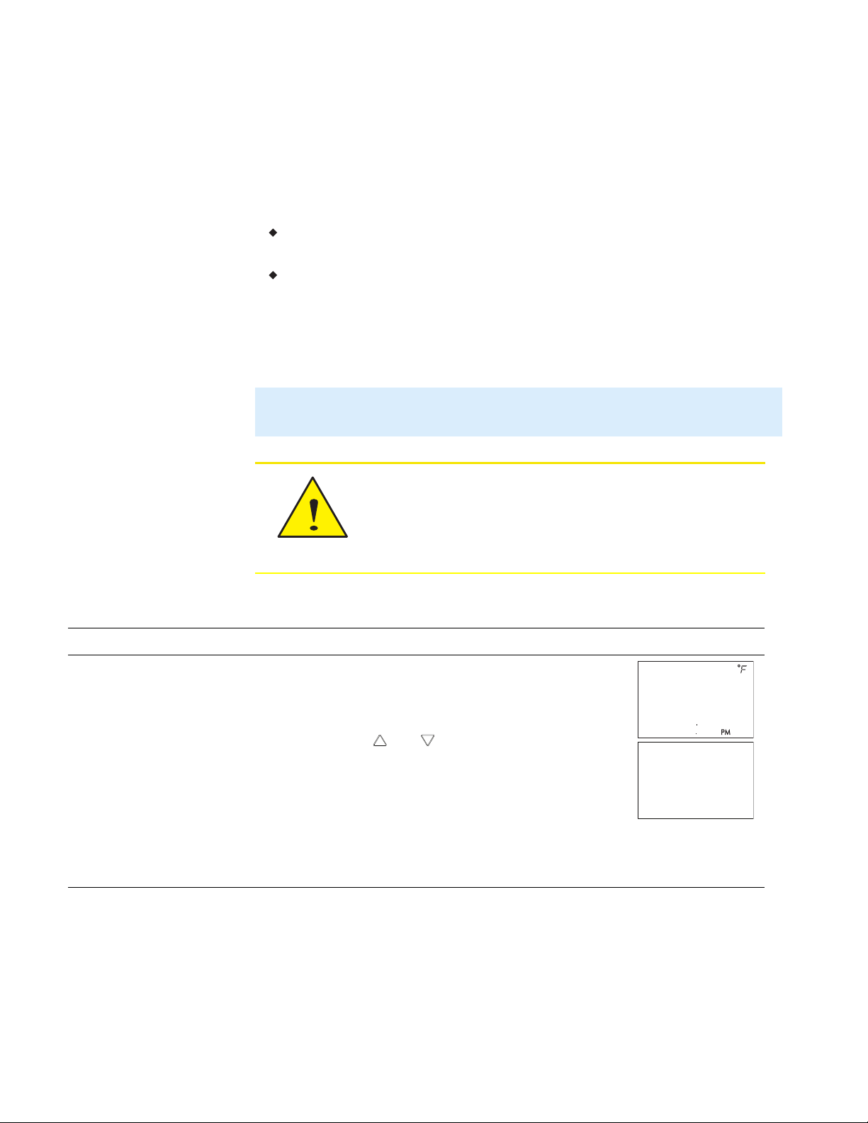
Connecting power
The controllers require a 24 volt, AC power source. Use the following
guidelines when choosing and wiring transformers to the controller.
Use a Class–2 transformer of the appropriate size to supply power to the
controller.
KMC Controls recommends powering only one controller from each
transformer.
Do not run 24 volt, AC power from within an enclosure to external
controllers.
Connect the 24 volt AC power supply to the power terminal block on the
lower right side of the controller. Connect the ground side of the transformer
to the ground terminal and the AC phase to the phase terminal. Power is
applied to the controller when the transformer is connected to power.
Illustration 2–7 Controller power terminals
Revision E 21
Page 22

Section 2: Installing the controllers SimplyVAV
Maintenance
SimplyVAV controllers require no routine maintenance. If necessary, clean
with a damp cloth and mild soap.
22 Revision E
Page 23

Set
Point
72
12S1
SimplyVAV
S e c t i o n 3 : Ch an g in g th e r o o m se t po i n t
This section covers topics for the end user in a facility.
Changing the SimplyVAV user functions with an STE-8001 or STE-8201 are
limited to changing the active setpoints in a room. The setpoints are entered
or changed using the buttons and display on the front of the sensor.
Quick start to changing setpoints
1.
Press any button to begin changing
setpoints.
2.
If required, enter Password 1.
3.
Press the up or down buttons to
change a sepoint value.
4.
Press the
advance to the next function.
button to save the value or
To enter or change the active setpoints you may need Password 1.
Tip: Once the following procedure is started, all steps must be completed in
order.
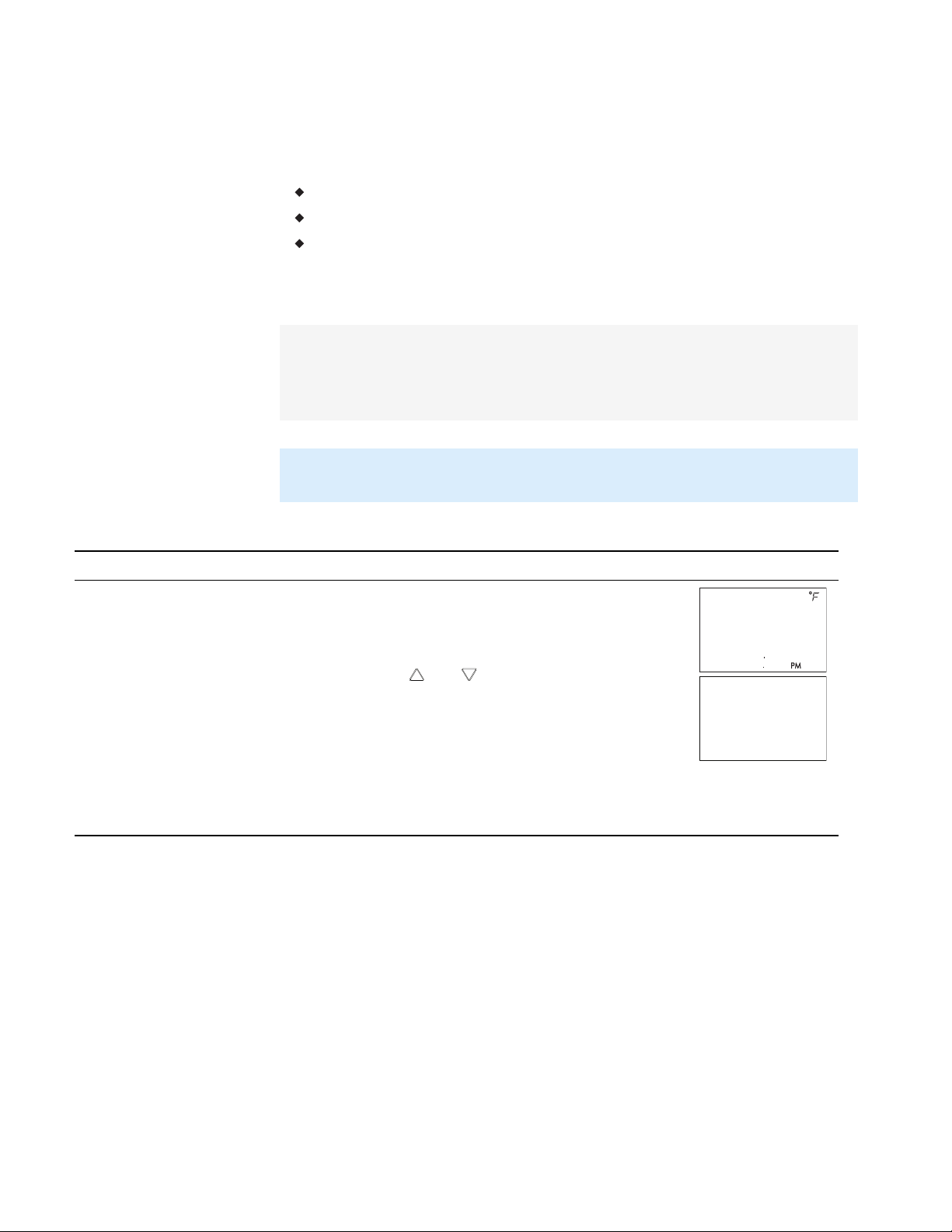
Changing room setpoints
Procedure Steps STE display
1 Starting display
Start from the temperature display.
Revision E 23
Page 24

Set
Point
PSW1
OOOO
Set
Point
745
COOLING
Set
Point
685
HEATING
Section 3: Changing the room setpoint SimplyVAV
Changing room setpoints (continued)
Procedure Steps STE display
1.
2 Enter Password 1.
Press any button. The display changes to
PSW1.
2.
Press the or buttons to change the first
digit.
3.
Press the
button to select the next digit.
Repeat for all four digits.
Note: If Password 1 has not previously been
entered, the display will change to the
occupied cooling setpoint display after Step 1.
1.
3 Set the active cooling
setpoint.
Press the or buttons to change the
cooling setpoint temperature. The setpoint
changes in increments of 0.5 degrees.
2.
Press the
button to save the value.
4 Set the active heating
setpoint.
The display advances to set the heating
setpoint.
1.
Press the or buttons to change the
heating setpoint temperature. The setpoint
changes in increments of 0.5 degrees.
2.
Press the
button to save the value.
The display returns to the temperature
display.
24 Revision E
Page 25

SimplyVAV
S e c t i o n 4 : Co n f ig u r in g t h e c o n t r o ll e r s
This topics in this section are advanced topics for control technicians and
engineers.
The configuration functions that are accessible through an STE-8000 series
sensor are all of the values and settings that are entered during the
installation and commissioning of a VAV terminal unit. Typically, these
functions do not change after the installation and commissioning process.
To set up the configuration functions, you will need the following items and
information.
Details about the VAV terminal unit including the configuration for fans
and reheat.
An STE-8001 or STE-8201 to use as a configuration tool.
The building automation system plans for controllers connected to a
network.
Users may change the active heating and cooling setpoints without accessing
the configuration functions. This procedure is covered in the topic Changing
the room setpoint on page 23.
Note: The instructions for the configuration functions cover all of the functions that
an STE-8000 sensor can set up in the SimplyVAV series of controllers. Not all
functions are available on every model of controller.
Configuration topics
Getting started with configuration
Entering system temperature setpoints and limits
Configuring the VAV Box options
Set the airflow setpoints
Advanced options
Restore Application
26
27
31
34
37
40
Revision E 25
Page 26

72
12S1
Set
Point
PSW2
OOOO
CNFG
Section 4: Configuring the controllers SimplyVAV
Getting started with configuration
Enter the configuration mode
Procedure Detailed steps STE display
1 Starting display
2 Enter Password 2.
For access to the configuration functions you will need Password 2.
If the controller has not been previously set up, no password is required.
A new Password 2 can be entered or changed in the advance functions.
See the topic Advanced options on page 37.
1.
Start at the temperature display.
2.
Press the and buttons together.
l If Password 2 is not required, the display
changes to CNFG.
l If required, enter Password 2. The display
changes to CNFG when Password 2 is
correct.
1.
Press the and buttons together and hold
them down until the display changes to PSW2.
2.
Press the or button to change the first
digit.
3.
Press the
Repeat for all four digits.
4.
When the button is pushed for the fourth
correct digit, the display changes to COMM.
button to select the next digit.
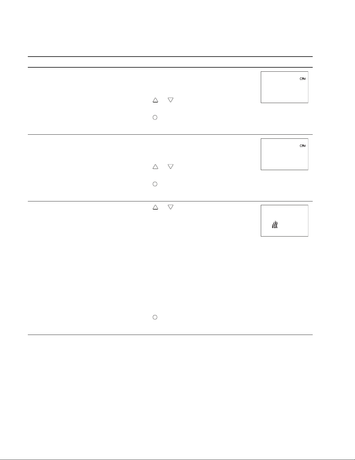
3 Select a configuration
26 Revision E
function.
Note: If Password 2 has not previously been
entered the display will change to the CNFG
display after Step 1.
Access to the configuration functions always start
CNFG
at the
display.
Page 27

72
12S1
PSW2
OOOO
Set
Point
Set
Point
CNFG
STPT
SimplyVAV Section 4: Configuring the controllers
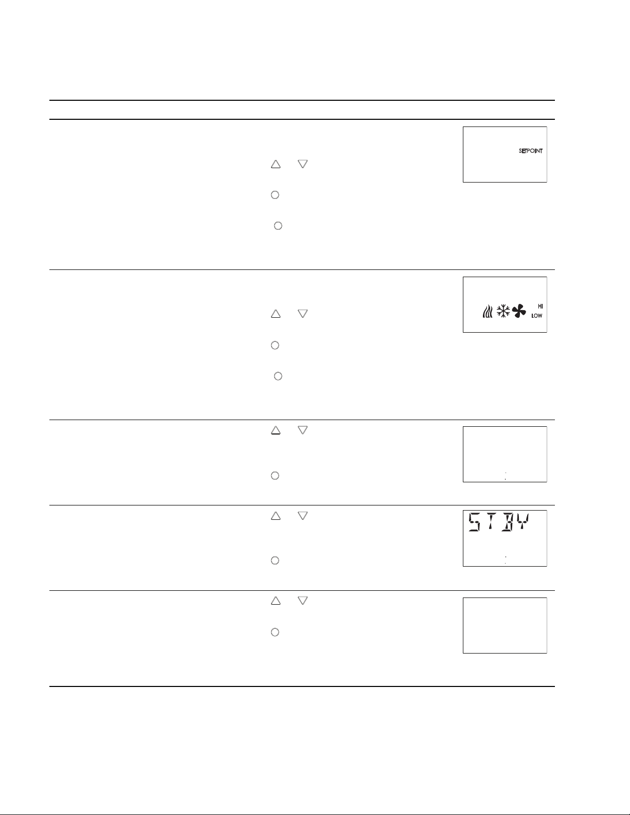
Entering system temperature setpoints and limits
The system temperature setpoints set the operational parameters and limits
for the VAV terminal unit.
The temperature setpoints include the following items.
Minimum cooling and maximum heating setpoints
Occupied and unoccupied cooling setpoints
Occupied and unoccupied heating setpoints
Changeover differential setpoint
Standby differential setpoint
Setting the temperature setpoints requires entering Password 2 which is
described in detail in the topic Getting started with configuration on page 26.
Tip: Once the following procedure is started, all steps must be completed in
order.
Procedure to set the temperature setpoints
Procedure Detailed steps STE display
1.
1 Start at the temperature
display.
Start at the temperature display.
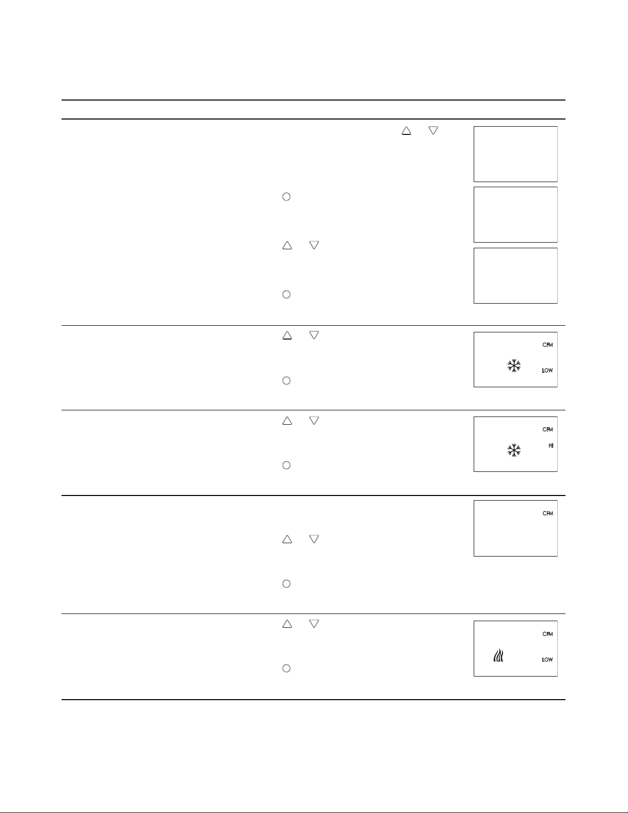
2 Select the setpoint
display.
2.
Press the and buttons together.
l If Password 2 is not required, the display
changes to CNFG.
l If required, enter Password 2. The display
changes to CNFG when Password 2 is
correct.
1.
From the CNFG display, press the or
buttons to show STPT.
2.
Press the
The display changes to STPT.
3.
Press the
changes to MIN.
button to select the CNFG options.
button to select STPT. The display
Revision E 27
Page 28

Set
Point
MIN
68O
Set
Point
MAX
78O
Set
Point
OCCL
74O
Section 4: Configuring the controllers SimplyVAV
Procedure to set the temperature setpoints (continued)
Procedure Detailed steps STE display
3 Set the minimum cooling
setpoint.
4 Set the maximum heating
setpoint.
5 Set the occupied cooling
setpoint.
This setpoint limits the lowest temperature that a
user can enter as the active setpoint.
1.
Press the or buttons to set the minimum
cooling setpoint. The setpoint will change in
0.5° increments.
2.
Press the
button to save the setpoint and
advance to the next function.
This setpoint limits the highest temperature a
user can enter as the active setpoint.
1.
Press the or buttons to set the maximum
heating setpoint. The setpoint will change in
0.5° increments.
2.
Press the
button to save the setpoint and
advance to the next function.
This setpoint is used as the active setpoint when
the space is occupied.
1.
Press the or buttons to set the occupied
cooling setpoint. The setpoint will change in
0.5° increments.
2.
Press the
button to save the setpoint and
advance to the next function.
28 Revision E
Note: This setpoint can also be changed as
described in the topic Changing the room
setpoint on page 23.
Page 29

Set
Point
OCHT
7OO
Set
Point
UNCL
8OO
Set
Point
UNHT
62O
Set
Point
74
CHNG
SimplyVAV Section 4: Configuring the controllers
Procedure to set the temperature setpoints (continued)
Procedure Detailed steps STE display
6 Set the occupied heating
setpoint.
7 Set the unoccupied
cooling setpoint.
This setpoint is used as the active setpoint when
the space is occupied.
1.
Press the or buttons to set the occupied
heating setpoint. The setpoint will change in
0.5° increments.
2.
Press the
button to save the setpoint and
advance to the next function.
Note: This setpoint can also be changed as
described in the section Changing the room
setpoint on page 23.
This setpoint is used as the active setpoint when
the space is unoccupied.
1.
Press the or buttons to set the
unoccupied cooling setpoint. The setpoint will
change in 0.5° increments.
2.
Press the
button to save the setpoint and
advance to the next function.
8 Set the unoccupied
heating setpoint.
9 Set the supply air
temperature changeover
setpoint.
Not used in all models.
This setpoint is used as the active setpoint when
the space is unoccupied.
1.
Press the or buttons to set the
unoccupied heating setpoint. The setpoint will
change in 0.5° increments.
2.
Press the
button to save the setpoint and
advance to the next function.
This setpoint sets the supply air temperature at
which the controller will change between heating
to cooling.
1.
Press the or buttons to set the
changeover setpoint. The setpoint will change
in 1° increments.
2.
Press the
button to save the setpoint and
advance to the next function.
Revision E 29
Page 30

Set
Point
O5
DIFF
Set
Point
OS
Set
Point
STPT
Section 4: Configuring the controllers SimplyVAV
Procedure to set the temperature setpoints (continued)
Procedure Detailed steps STE display
10 Set the minimum
temperature differential
setpoint.
11 Set the standby
differential setpoint.
12 Select a new
configuration function or
exit.
The minimum allowable temperature value
between the cooling and heating setpoints.
1.
Press the or buttons to set the
differential setpoint. The setpoint will change
in 1° increments.
2.
Press the
button to save the setpoint and
advance to the next function.
The standby setpoint is calculated by adding or
subtracting the offset value to or from the value
of the occupied setpoint.
1.
Press the or buttons to set the standby
differential setpoint. The setpoint will change
in 1° increments.
2.
Press the
button to save the setpoint and
advance to the next function.
1.
Press the or buttons to select one of the
following:
BOX, FLOW, ADVC, or RSTR options
2.
Press the
BACK to choose another configuration
function.
EXIT to return to the temperature display.
button to select the next function.
30 Revision E
Page 31

72
12S1
PSW2
OOOO
Set
Point
Set
Point
CNFG
STPT
BOX
SimplyVAV Section 4: Configuring the controllers
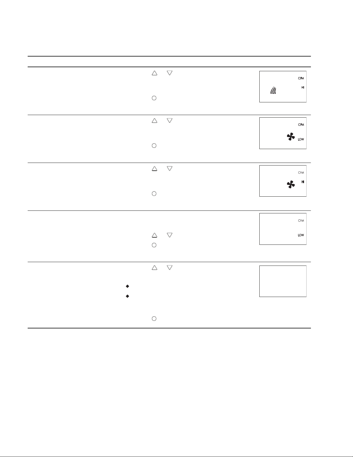
Configuring the VAV Box options
Tip: Once the following procedure is started, all steps must be completed in
Procedure to set the box functions
Procedure Detailed steps STE display
1 Starting display
The box options set the controller for the specific mechanical installation of
the VAV terminal unit. The box options include the following items.
The K-factor for the VAV terminal unit. If the K-factor is not available,
see the topic K-factors on page 83.
Reheat configuration (optional)
Fan configuration (optional)
Direction of damper to close
Setting the box options requires entering Password 2 which is described in
the topic Getting started with configuration on page 26.
order.
1.
Start at the temperature display.
2 Select the box settings
display.
2.
Press the and buttons together.
l If Password 2 is not required, the display
changes to CNFG.
l If required, enter Password 2. The display
changes to CNFG when Password 2 is
correct.
1.
From the CNFG display, press the or
buttons to show the BOX display.
2.
Press the
The display changes to STPT.
3.
Press the or buttons to change the
display to BOX.
4.
Press the
button to select the CNFG options.
button to select BOX.
Revision E 31
Page 32
Set
Point
9O4
PKFT
Set
Point
9O4
SKFT
Set
Point
NONE
REHT
Section 4: Configuring the controllers SimplyVAV
Procedure to set the box functions (continued)
Procedure Detailed steps STE display
3 Set the primary VAV
terminal unit K-factor.
4 Set the secondary VAV
terminal unit K-factor.
Not used in all models.
5 Set the mode of reheat
for the terminal unit.
Not used in all models.
The K-factor is supplied by the manufacturer of
the VAV terminal unit. Typically it is on the label
with the unit airflow information.
1.
Press the or buttons to set the primary
K-factor.
2.
Press the
advance to the next function.
The K-factor is supplied by the manufacturer of
the VAV terminal unit. Typically it is on the label
with the unit airflow information.
1.
Press the or buttons to set the secondary
K-factor.
2.
Press the
advance to the next function.
1.
Press the or buttons to choose one of the
following reheat options.
button to save the entry and
button to save the entry and
None—Reheat is not enabled.
Staged—Enables staged reheat.
Modulating—The analog reheat output varies
from 0-10 volts DC.
Floating—The reheat outputs control a tristate
actuator.
Time proportional—Controls a thermal wax
valve with a 24-volt triac output.
2.
Press the
and advance to the next function.
button to save the reheat option
32 Revision E
Page 33
Set
Point
NONE
FAN
Set
Point
CCW
DDIR
Set
Point
BOX
SimplyVAV Section 4: Configuring the controllers
Procedure to set the box functions (continued)
Procedure Detailed steps STE display
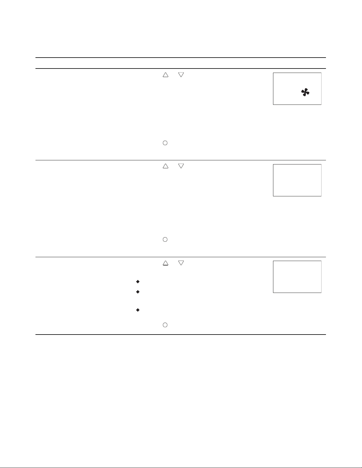
1.
6 Set the fan option.
Press the or buttons to choose one of the
following fan options.
Not used in all models.
None—No fan is connected to the controller.
Series—The VAV unit includes a series fan.
Parallel—The VAV unit includes a parallel fan.
2.
7 Set the damper direction
to close.
Press the
advance to the next function.
1.
Press the or buttons to which direction
to damper moves to close.
button to save the fan option and
CCW—The actuator turns counterclockwise to
close the damper.
8 Select a new
configuration function or
exit.
CW—The actuator turns clockwise to close the
damper.
2.
Press the
and advance to the next function.
1.
Press the or buttons to select one of the
following:
button to save the damper option
STPT, FLOW, ADVC. or RSTR options
BACK to choose another configuration
function
EXIT to return to the temperature display.
2.
Press the
button to select the next function.
Revision E 33
Page 34
72
12S1
PSW2
OOOO
Section 4: Configuring the controllers SimplyVAV
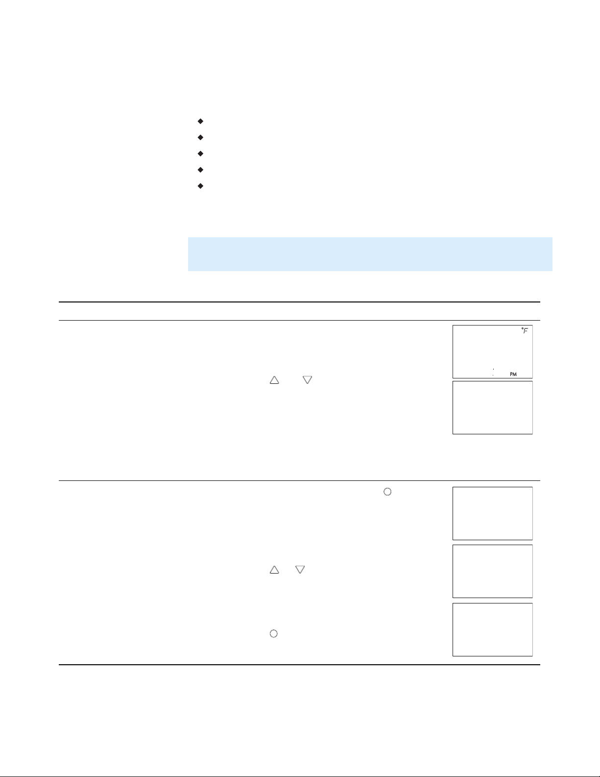
Set the airflow setpoints
Note: If the VAV unit is a heat only or cooling only unit, the airflow setpoints for
Tip: Once the following procedure is started, all steps must be completed in
Procedure to set the airflow setpoints
Procedure Detailed steps STE display
1 Starting display
The airflow setpoints set the airflow limits for the VAV terminal unit.
Airflow heating and cooling minimum and maximum limits
Auxiliary flow setpoint (optional)
Minimum and maximum fan speeds (optional)
Setting the airflow setpoints requires entering Password 2 which is described
in the topic Getting started with configuration on page 26.
the unused mode must be set within the range of the mode in use. Failure to
set the unused setpoints correctly will result in unpredictable or erroneous
air balancing settings.
order.
1.
Start at the temperature display.
2.
Press the and buttons together.
l If Password 2 is not required, the display
changes to CNFG.
l If required, enter Password 2. The display
changes to CNFG when Password 2 is
correct.
34 Revision E
Page 35
Set
Point
Set
Point
CNFG
STPT
FLOW
Set
Point
OO
MNCL
Set
Point
3SO
MXCL
Set
Point
200
AUXF
Set
Point
OO
MNHT
SimplyVAV Section 4: Configuring the controllers
Procedure to set the airflow setpoints (continued)
Procedure Detailed steps STE display
1.
2 Select the flow setpoint
display.
3 Set the cooling minimum
airflow limit.
From the CNFG display, press the or
buttons to show the CNFG display.
2.
Press the
The display changes to STPT.
3.
Press the or buttons to change the
display to FLOW.
4.
Press the
changes to MNCL.
1.
Press the or buttons to set the minimum
limit for cooling airflow. The setpoint changes
in 1 CFM increments.
2.
Press the
advance to the next function.
button to select the CNFG options.
button to select FLOW. The display
button to save the setpoint and
4 Set the cooling maximum
airflow limit.
5 Set the axillary airflow
setpoint.
Not used for all models.
6 Set the heating minimum
airflow limit
1.
Press the or buttons to set the maximum
limit for cooling airflow. The setpoint changes
in 1 CFM increments.
2.
Press the
advance to the next function.
This setpoint sets the airflow for when reheat is
active auxiliary airflow.
1.
Press the or buttons to set a value for the
auxillary airflow. The setpoint changes in 1
CFM increments.
2.
Press the
advance to the next function.
1.
Press the or buttons to set the minimum
limit for heating airflow. The setpoint will
change in 1 CFM increments.
2.
Press the
advance to the next function.
button to save the setpoint and
button to save the setpoint and
button to save the setpoint and
Revision E 35
Page 36
Set
Point
3SO
MXHT
Set
Point
2O
MINF
Set
Point
1OO
MAXF
Set
Point
1OO
DLMN
Set
Point
FLOW
Section 4: Configuring the controllers SimplyVAV
Procedure to set the airflow setpoints (continued)
Procedure Detailed steps STE display
1.
7 Set the heating maximum
airflow limit.
Press the or buttons to set the maximum
limit for heating airflow. The setpoint will
change in 1 CFM increments.
2.
Press the
button to save the setpoint and
advance to the next function.
1.
8 Set the minimum limit
for fan speed.
Press the or buttons to set the minimum
limit for the fan speed. The setpoint will
change in 1% increments.
Not used for all models.
2.
Press the
button to save the setpoint and
advance to the next function.
1.
9 Set the maximum limit
for fan speed.
Press the or buttons to set the maximum
limit for the fan speed. The setpoint will
change in 1% increments.
Not used for all models.
2.
Press the
button to save the setpoint and
advance to the next function.
10 Set the dual duct
minimum airflow.
Not used for all models.
11 Select a new
configuration function or
exit.
This setpoint is for the minimum airflow when a
dual-duct system is at temperature setpoint.
1.
Press the or buttons.
2.
Press the
button to save the setpoint and
advance to the next function.
1.
Press the or buttons to select one of the
following:
STPT, BOX, ADVC, or RSTR options
BACK to choose another configuration
function EXIT.
2.
Press the
button to select the next function.
36 Revision E
Page 37
72
12S1
PSW2
OOOO
Set
Point
Set
Point
CNFG
STPT
ADVC
SimplyVAV Section 4: Configuring the controllers
Advanced options
Tip: Once the following procedure is started, all steps must be completed in
Table 4–1 Procedure to set the advanced options
Procedure Steps STE display
1 Starting display
The advanced options set up passwords and special features in the controller.
Establish or change Password 1 and Password 2
Set timers for standby and override (optional)
Enable automatic occupancy (optional)
Enable discharge air temperature control (optional)
Calibrate the sensor
Setting the advance options requires entering Password 2 which is described
in the topic Getting started with configuration on page 26.
order.
1.
Start at the temperature display.
2.
Press the and buttons together.
2 Select the advanced
display.
l If Password 2 is not required, the display
changes to CNFG.
l If required, enter Password 2. The display
changes to CNFG when Password 2 is
correct.
1.
From the CNFG display, press the
show the STPT display.
2.
Press the or buttons to change the
display to ADVC.
3.
Press the
button to select ADVC.
button to
Revision E 37
Page 38
Set
Point
Set
Point
PSW1
OOOO
Set
Point
Set
Point
PSW2
OOOO
Set
Point
3O
OVRD
Set
Point
15
Set
Point
DISABLE
DAT
Section 4: Configuring the controllers SimplyVAV
Procedure to set the advanced options (continued)
Procedure Steps STE display
3 Change Password 1.
4 Change Password 2.
Note: Entering four zeros (0000) removes the
password.
1.
Press the or buttons to change the first
digit.
2.
Press the
button to select the next digit.
Repeat for all four digits.
3.
When the
button is pressed for the last
digit, the new password is saved and the
display advances.
Note: Entering four zeros (0000) removes the
password.
1.
Press the or buttons to change the first
digit.
2.
Press the
button to select the next digit.
Repeat for all four digits.
3.
When the
button is pressed for the last
digit, the new password is saved and the
display advances.
5 Set the local unoccupied
override timer.
Applies only to STE-6017
sensors.
6 Set the standby time
Applies only to STE-8201
sensors.
7 Set discharge air
temperature limiting.
Not used for all models.
Required for reheat.
1.
Press the or buttons to set the local
unoccupied override timer. The value will
change in 1 minute increments.
2.
Press the
button to save the setpoint and
advance to the next function.
1.
Press the or buttons to set the time for
the standby time. The value will change in 1
minute increments.
2.
Press the
button to save the setpoint and
advance to the next function.
1.
Press the or buttons to enable or disable
discharge air temperature limiting.
2.
Press the
button to save the setpoint and
advance to the next function.
38 Revision E
Page 39
Set
Point
DISABLE
AUMD
Set
Point
OO
CALIB
Set
Point
ADVC
SimplyVAV Section 4: Configuring the controllers
Procedure to set the advanced options (continued)
Procedure Steps STE display
1.
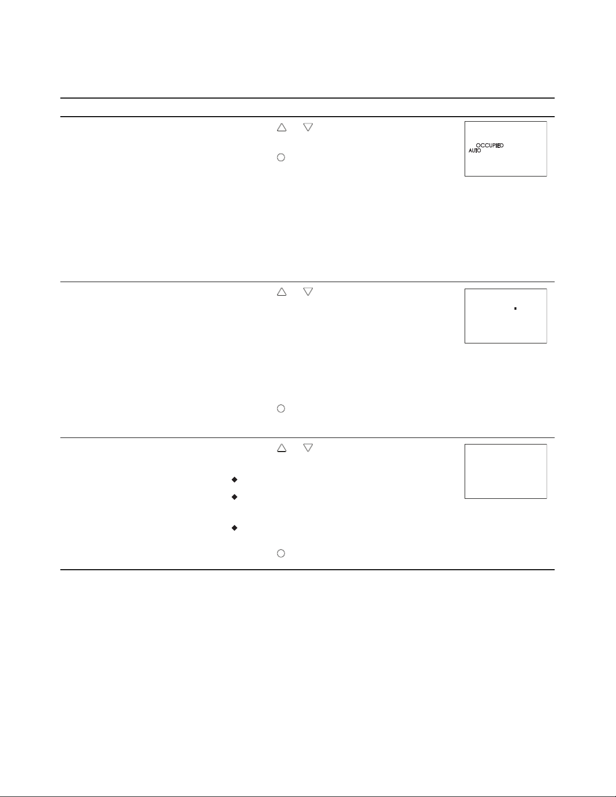
8 Set the automatic
occupancy mode.
Requires a discharge air
temperature sensor.
Press the or buttons to enable or disable
discharge air temperature limiting.
2.
Press the
button to save the setpoint and
advance to the next function.
Enable The controller will automatically
changed to the unoccupied state when it
detects the loss of primary air supply.
Disable The controller will remain in the
occupied mode regardless of the primary
air supply.
1.
9 Set the temperature
sensor calibration
constant.
Press the or buttons to set the calibration
constant. The setpoint will change in0.1
minute increments.
l For a low input reading enter a positive
correction value.
l For a high input reading enter a negative
correction value.
10 Select a new
configuration function or
exit.
2.
Press the
button to save the setpoint and
advance to the next function.
1.
Press the or buttons to select one of the
following:
STPT, FLOW, BOX, or RSTR options
BACK to choose .another configuration
function
EXIT to return to the temperature display.
2.
Press the
button to select the next function.
Revision E 39
Page 40
Caution
72
12S1
PSW2
OOOO
Section 4: Configuring the controllers SimplyVAV
Restore Application
Tip: Once the following procedure is started, all steps must be completed in
Choose the RSTR function to reset the SimplyVAV controller to the original
configuration and settings. Use it also to change the units of measure to
display on a SimplyVAV sensor. There are two versions of the application
program in the controller.
The Metric version displays temperature in Celsius and uses metric
values for units of measure.
The English version displays temperature in Fahrenheit and uses English
values for units of measure.
Access to the Restore Application function requires entering Password 2
which is described in the topic Getting started with configuration on page 26.
order.
Choosing RSTR deletes all previously configured values
including balancing values and passwords. Only the
BACnet communications settings will remain unchanged.
Procedure to restore application
Procedure Detailed steps STE display
1.
1 Starting display
Start at the temperature display.
2.
Press the and buttons together.
l If Password 2 is not required, the display
changes to CNFG.
l If required, enter Password 2. The display
changes to CNFG when Password 2 is
correct.
40 Revision E
Page 41
Set
Point
Set
Point
CNFG
STPT
RSTR
Set
Point
METRIC
RSTR
ENGLISH
RSTR
SimplyVAV Section 4: Configuring the controllers
Procedure to restore application (continued)
Procedure Detailed steps STE display
1.
2 Select the restore settings
display.
From the CNFG display, press the or
buttons to show the CNFG display.
2.
Press the
The display changes to STPT.
3.
Press the or buttons to change the
display to RSTR.
button to select the CNFG options.
Caution: Choosing RSTR deletes all
previously entered values and returns the
controller to the manufacturer's settings. Only
the BACnet communications settings will
remain unchanged.
3 Choose the application.
4.
Press the
1.
Press the or buttons to choose ENGLISH
or METRIC.
button to select RSTR.
Metric The sensor displays temperature in
Celsius and uses metric values for units of
measure.
English The sensor displays temperature in
Fahrenheit and uses English values for units of
measure.
2.
Press the
advance to the next function.
button to save the entry and
Revision E 41
Page 42

Section 4: Configuring the controllers SimplyVAV
42 Revision E
Page 43

SimplyVAV
S e c t i o n 5 : B ala nc i ng ai r fl o w
Topics in this section are for control technicians or engineers who will be
balancing the airflow in the controllers.
The airflow balancing procedure described in this section requires the
following items.
A flow hood or other accurate method to measure airflow.
An STE-8001 or STE-8201 wall sensor. If the system does not include one
of these sensors, temporarily disconnect the installed sensor and connect
an STE-8001 as a service tool.
The engineering design specifications for the minimum and maximum
airflow setpoints.
Password 2 which is described in the topic Getting started with
configuration on page 26.
Note: If the VAV unit is a heat only or cooling only unit, the airflow setpoints for
the unused mode must be set within the range of the mode in use. Failure to
set the unused setpoints correctly will result in unpredictable or erroneous
air balancing settings. See Set the airflow setpoints on page 34 for the
procedure to adjust the setpoints.
Note: Starting the balancing procedure erases all previous airflow correction
factors. The airflow readings displayed by the STE-8001 are the actual
uncorrected airflow readings as measured by the controller.
Tip: Once the following procedure is started, all steps must be completed in
order.
Revision E 43
Page 44

72
12S1
PSW2
OOOO
Set
Point
Set
Point
CNFG
COMM
BLNC
PRI
Section 5: Balancing airflow SimplyVAV
Table 5–1 The airflow balancing procedure
Procedure Steps STE display
1.
1 Starting display
2 Select the CNFG display.
Start at the temperature display.
2.
Press the and buttons together.
l If Password 2 is not required, the display
changes to CNFG.
l If required, enter Password 2. The display
changes to CNFG when Password 2 is
correct.
1.
From the CNFG display, press the or
buttons to advance to COMM and the BLNC
display.
2.
Press the
advances to PRI.
3.
Press the
button to select BLNC. The display
button to select PRI.
44 Revision E
Page 45

Set
Point
Set
Point
PMAX
OO
Set
Point
Set
Point
PMIN
OO
SimplyVAV Section 5: Balancing airflow
The airflow balancing procedure (continued)
Procedure Steps STE display
3 Measure and enter the
actual maximum primary
airflow
4 Measure and enter the
actual minimum primary
airflow
The display begins flashing PMAX and also
displays the actual airflow at the bottom.
Note: The airflow will attempt to stabilize on
the highest value for either the cooling or
heating maximum airflow even if only one
mode is operational.
Note: The airflow displayed by the STE-8000
in this step is the actual, uncorrected airflow.
1.
Wait for the maximum airflow value to
stabilize.
2.
With a flow hood, measure the actual airflow.
3.
Press the
button to advance to the entry
display. PMAX stops flashing.
4.
Press the or buttons to enter the
measured airflow.
5.
Press the
button to save the measured
airflow. The display changes to PMIN.
The display begins flashing PMIN and also
displays the actual airflow at the bottom.
Note: The airflow will attempt to stabilize on
the lowest value for either the cooling or
heating minimum airflow even if only one
mode is operational.
Revision E 45
Note: The airflow displayed by the STE-8000
in this step is the actual, uncorrected airflow.
1.
Wait for the minimum airflow value to
stabilize.
2.
With a flow hood, measure the actual airflow.
3.
Press the
button to advance to the entry
display. PMIN stops flashing.
4.
Press the or buttons to enter the
measured airflow.
5.
Press the
button to save the measured
airflow. The display advances to PRI.
Page 46

Set
Point
PRI
SEC
Set
Point
Set
Point
SMAX
OO
Section 5: Balancing airflow SimplyVAV
The airflow balancing procedure (continued)
Procedure Steps STE display
1.
5 Advance or exit
Press the or buttons to select one of the
following:
SEC to balance the secondary VAV for dual
duct systems. Choosing SEC advances to
the SMAX display. This is available only on
dual duct models.
BACK to choose another commissioning
function
EXIT to return to the temperature display.
2.
Press the
button to select the next function.
6 Measure and enter the
actual maximum
secondary airflow
The display begins flashing SMAX and also
displays the actual airflow at the bottom.
Note: The airflow displayed by the STE-8000
in this step is the actual, uncorrected airflow.
1.
Wait for the maximum airflow value to
stabilize.
2.
With a flow hood, measure the actual airflow.
3.
Press the
button to advance to the entry
display. SMAX stops flashing.
4.
Press the or buttons to enter the
measured airflow.
5.
Press the
button to save the measured
airflow. The display advances to SMIN.
46 Revision E
Page 47

Set
Point
Set
Point
SMIN
OO
Set
Point
SEC
SimplyVAV Section 5: Balancing airflow
The airflow balancing procedure (continued)
Procedure Steps STE display
7 Measure and enter the
actual minimum
secondary airflow
8 Advance or exit
The display begins flashing SMIN and also
displays the actual airflow at the bottom.
Note: The airflow displayed by the STE-8000
in this step is the actual, uncorrected airflow.
1.
Wait for the minimum airflow value to
stabilize.
2.
With a flow hood, measure the actual airflow.
3.
Press the
button to advance to the entry
display. SMIN stops flashing.
4.
Press the or buttons to enter the
measured airflow.
5.
Press the
button to save the measured
airflow. The display advances to SEC.
1.
Press the or buttons to select one of the
following:
PRI to balance the primary VAV for dual
duct systems
BACK to choose another configuration
function.
2.
Press the
EXIT to return to the temperature display.
button to select the next function.
Revision E 47
Page 48

Section 5: Balancing airflow SimplyVAV
48 Revision E
Page 49

SimplyVAV
S e c t i o n 6 : A p p lic a tio n dr a w in g s
This section covers the drawings, materials, and instructions for specific
VAV applications.
Each SimplyVAV model is designed for a specific set of applications. The
following topics are for control technicians and engineers that will plan for
and install controllers for SimplyVAV applications.
Submittal sheets for all of these applications are available from the Resources
page at www.SimplyVAV.com.
Application drawings in this section
Cooling or heating without reheat
Staged reheat
Modulating reheat
Time proportional reheat
Floating reheat
Dual-duct application
50
51
52
53
54
55
Revision E 49
Page 50
24 VAC
Duct
Temp
Sensor
ON CTS
1 2
COMM
READY
AI1
AI5
GND
AO4
AO3
SC
BO8
BO5
BO6
SC
BO7
24VAC
AI6
GND
AI7
T-STAT/
SENSOR
-A
+B
S
EOL
BACnet MS/TP
Section 6: Application drawings SimplyVAV
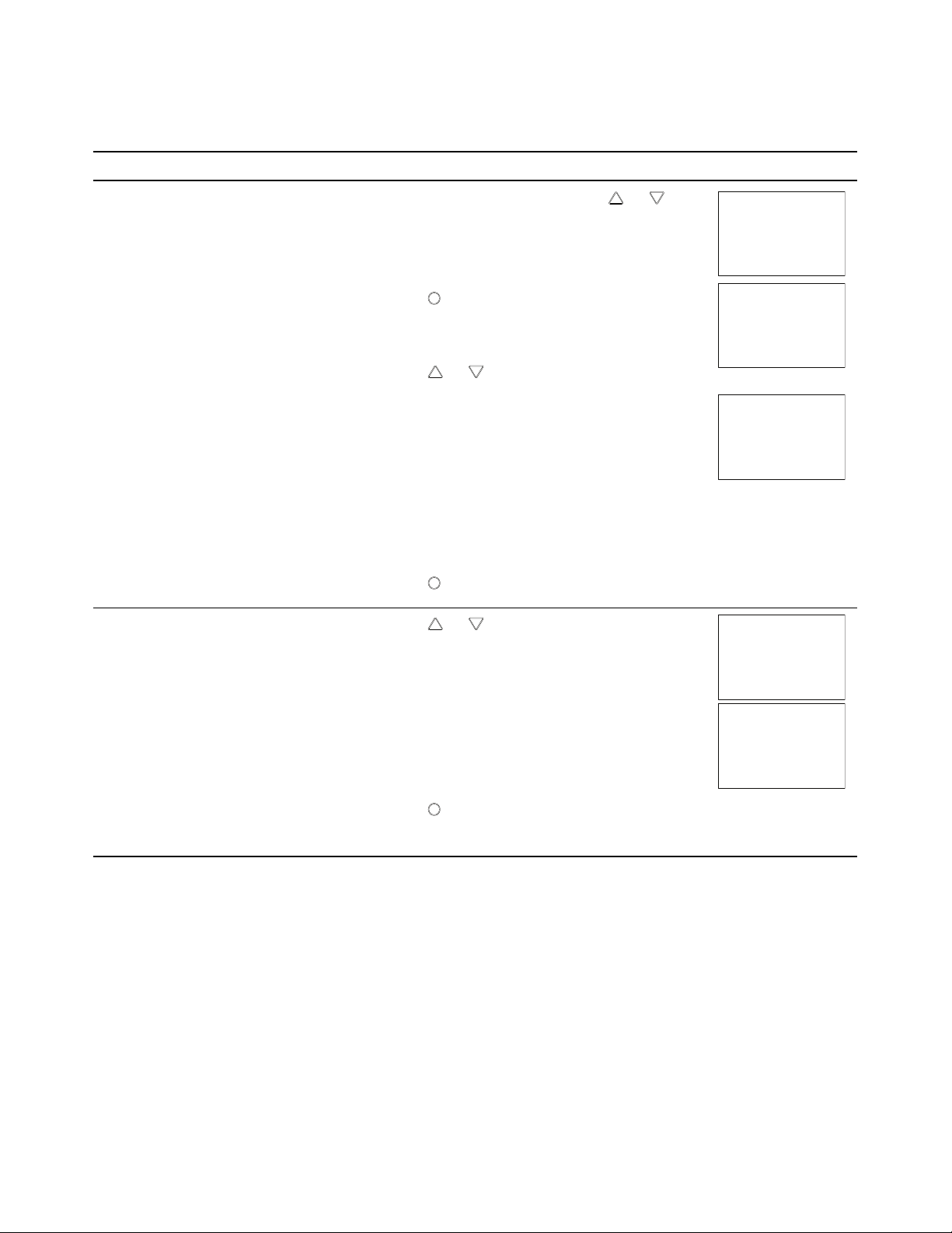
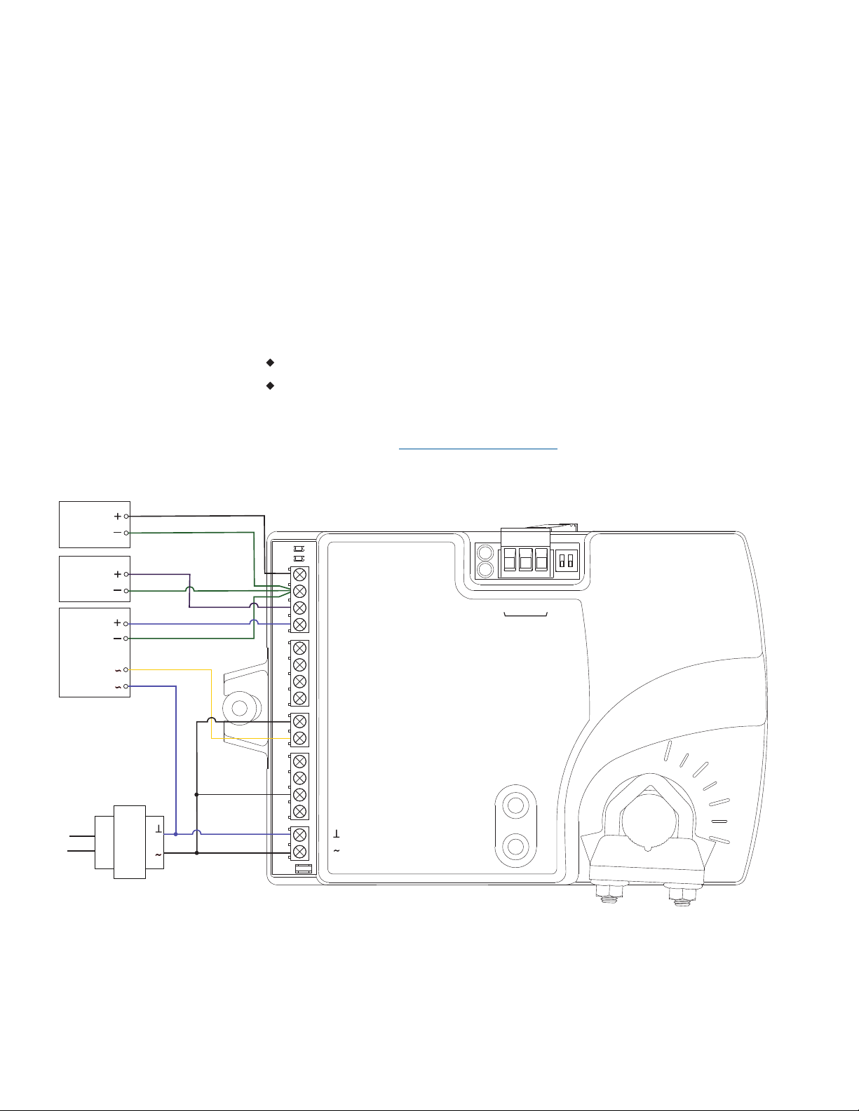
Cooling or heating without reheat
The BAC-8001 is configured for single-duct cooling VAV control without
reheat. Connect the controller as shown in the illustration Cooling or heating
application drawing on page 50. A BAC-8005 or BAC-8205 may also be used
for this application.
For cooling and heating, a duct temperature sensor is required for Discharge
Air Temperature limiting and automatic changeover. See the topic Advanced
options on page 37 for instructions to enable Discharge Air Temperature
limiting.
Submittal sheets for several variations of this application are available from
the Resources page at www.SimplyVAV.com.
Illustration 6–1 Cooling or heating application drawing
50 Revision E
Page 51
ON CTS
1 2
COMM
READY
AI1
AI5
GND
AO4
AO3
SC
BO8
BO5
BO6
SC
BO7
24VAC
AI6
GND
AI7
T-STAT/
SENSOR
-A
+B
S
EOL
BACnet MS/TP
Fan
Speed
Duct
Temp
Sensor
Stage 1
Stage 2
Stage 3
24VAC
Fan start
Reheat
24 VAC
SimplyVAV Section 6: Application drawings
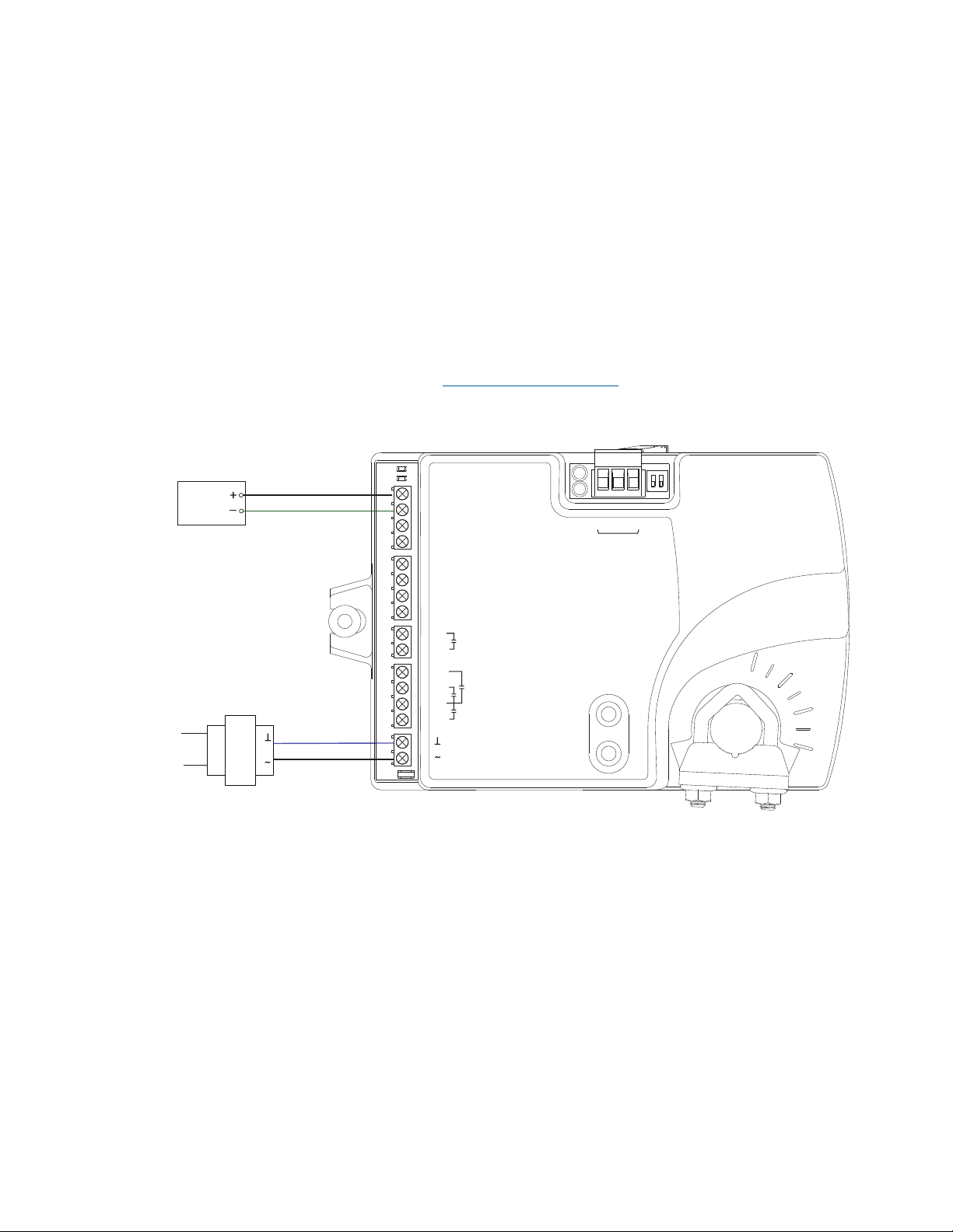
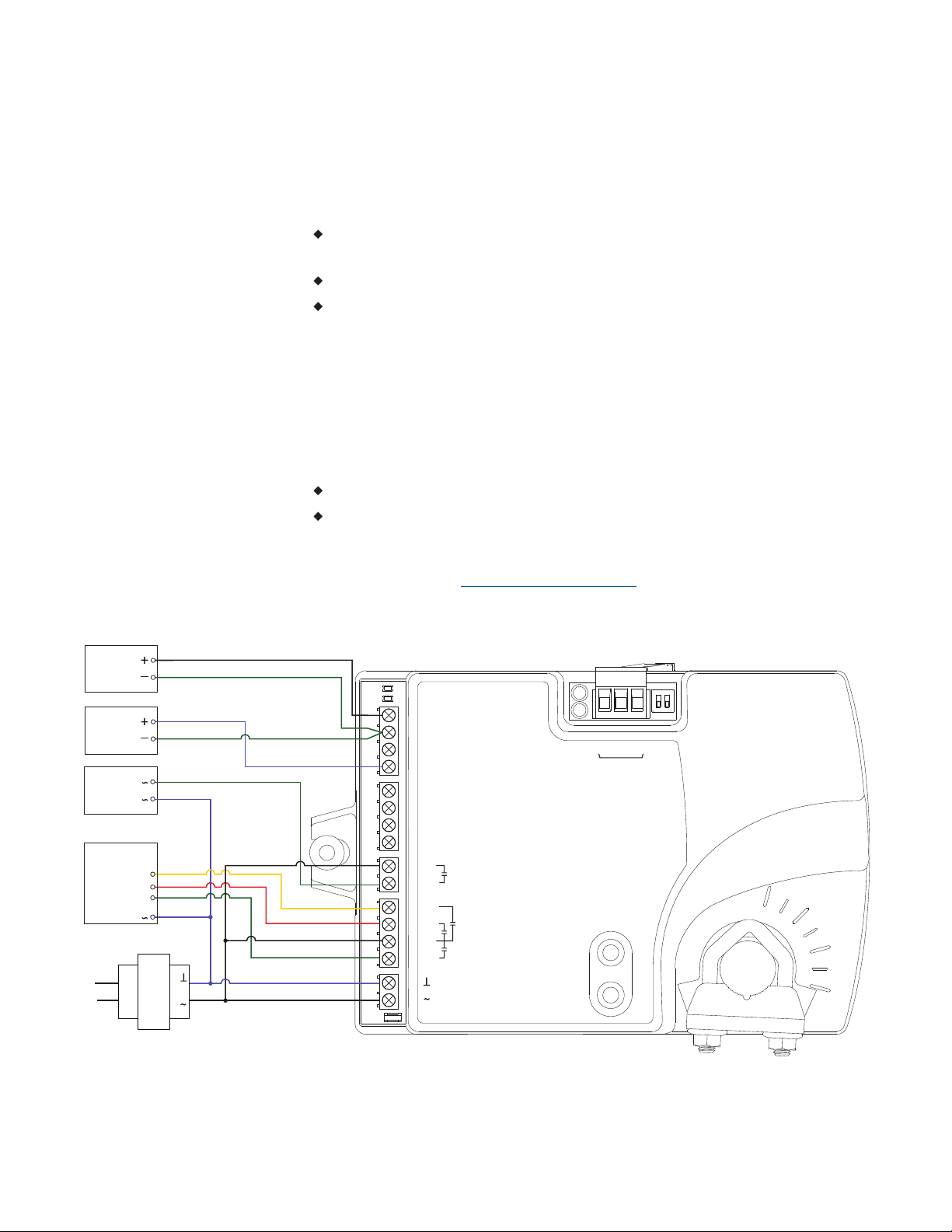
Staged reheat
This application is for BAC-8005 or BAC-8205 controllers. The controllers are
configured to switch reheat units that are controlled with 24 volts AC. Reheat
units with up to three stages of reheat can be controlled by these controllers.
For one-stage or electric reheat or hot water reheat with an on/off valve,
use only output terminal BO6.
For two-stage reheat use output terminals BO6 and BO7.
For three-stage reheat use output terminals BO6, BO7, and BO8.
For cooling and heating, a duct temperature sensor is required for Discharge
Air Temperature limiting and automatic changeover. See the topic Advanced
options on page 37 for instructions to enable Discharge Air Temperature
limiting.
When connecting the controller to a fan powered VAV unit, the fan circuits
must be compatible with the following specifications.
The fan start circuit is a 24 volt AC pilot duty output.
The fan speed output is 0-10 volts DC.
Submittal sheets for several variations of this application are available from
the Resources page at www.SimplyVAV.com.
Illustration 6–2 BAC-8005 and BAC-8205 with three-stage reheat
Revision E 51
Page 52
ON CTS
1 2
COMM
READY
AI1
AI5
GND
AO4
AO3
SC
BO8
BO5
BO6
SC
BO7
24VAC
AI6
GND
AI7
T-STAT/
SENSOR
-A
+B
S
EOL
BACnet MS/TP
Fan
Speed
0-10 VDC
Duct
Temp
Sensor
Analog
Heat
24VAC
Fan start
24 VAC
Class 2
Section 6: Application drawings SimplyVAV
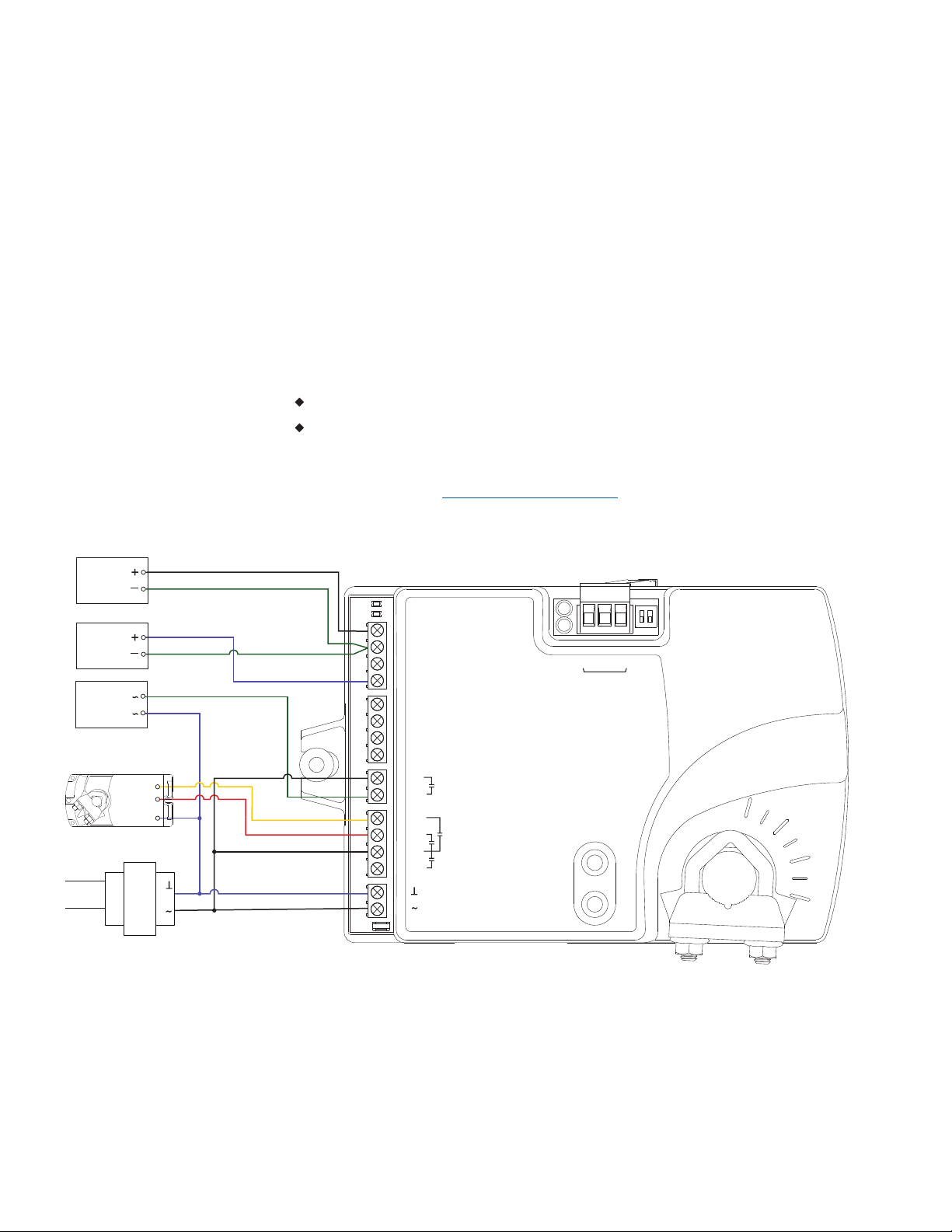
Modulating reheat
This application is for a BAC-8005 or BAC-8205 controller. The modulating
option for reheat can control either an electric reheat unit with an analog
input or a modulating hot water valve. The analog reheat output at output
terminal AO3 varies between 0 and 10 volts DC.
For cooling and heating, a duct temperature sensor is required for Discharge
Air Temperature limiting and automatic changeover. See the topic Advanced
options on page 37 for instructions to enable Discharge Air Temperature
limiting.
When connecting the controller to a fan powered VAV unit, the fan circuits
must be compatible with the following specifications.
The fan start circuit is a 24 volt AC pilot duty output.
The fan speed output is 0-10 volts DC.
Submittal sheets for several variations of this application are available from
the Resources page at www.SimplyVAV.com.
Illustration 6–3 Modulating reheat
52 Revision E
Page 53

ON CTS
1 2
COMM
READY
AI1
AI5
GND
AO4
AO3
SC
BO8
BO5
BO6
SC
BO7
24VAC
AI6
GND
AI7
T-STAT/
SENSOR
-A
+B
S
EOL
BACnet MS/TP
Fan
Speed
Duct
Temp
Sensor
24VAC
Fan start
24 VAC
24VAC THERMAL
ACTUATOR
SimplyVAV Section 6: Application drawings
Time proportional reheat
This application is for a BAC-8005 or BAC-8205 controller. The time
proportional reheat option is typically used in hydronic systems with a hot
water reheat coil and a wax top control valve.The reheat output is a triac that
can switch up to 1ampere at 24volts AC.
For cooling and heating, a duct temperature sensor is required for Discharge
Air Temperature limiting and automatic changeover. See the topic Advanced
options on page 37 for instructions to enable Discharge Air Temperature
limiting.
When connecting the controller to a fan powered VAV unit, the fan circuits
must be compatible with the following specifications.
The fan start circuit is a 24 volt AC pilot duty output.
The fan speed output is 0-10 volts DC.
Submittal sheets for several variations of this application are available from
the Resources page at www.SimplyVAV.com.
Illustration 6–4 Time proportional reheat
Revision E 53
Page 54
ON CTS
1 2
COMM
READY
AI1
AI5
GND
AO4
AO3
SC
BO8
BO5
BO6
SC
BO7
24VAC
AI6
GND
AI7
T-STAT/
SENSOR
-A
+B
S
EOL
BACnet MS/TP
Fan
Speed
Duct
Temp
Sensor
24VAC
Fan start
24 VAC
Open
Close
Common
Section 6: Application drawings SimplyVAV
Floating reheat
This application is for a BAC-8005 or BAC-8205 controller. Use the floating
reheat option in hydronic systems that are controlled by an actuator with tristate inputs. The reheat outputs are triacs that can switch up to 1ampere at
24volts AC.
For cooling and heating, a duct temperature sensor is required for Discharge
Air Temperature limiting and automatic changeover. See the topic Advanced
options on page 37 for instructions to enable Discharge Air Temperature
limiting.
When connecting the controller to a fan powered VAV unit, the fan circuits
must be compatible with the following specifications.
The fan start circuit is a 24 volt AC pilot duty output.
The fan speed output is 0-10 volts DC.
Submittal sheets for several variations of this application are available from
the Resources page at www.SimplyVAV.com.
Illustration 6–5 Floating reheat
54 Revision E
Page 55
ON CTS
1 2
COMM
READY
AI1
AI5
GND
AO4
AO3
SC
BO8
BO5
BO6
SC
BO7
24VAC
AI6
GND
AI7
T-STAT/
SENSOR
-A
+B
S
EOL
BACnet MS/TP
P2
CW
COM
P1
CCW
24VAC
P OUT
MOTOR
F.B.
POT
24 VAC
BAC-8007
TSP-8001
SimplyVAV Section 6: Application drawings
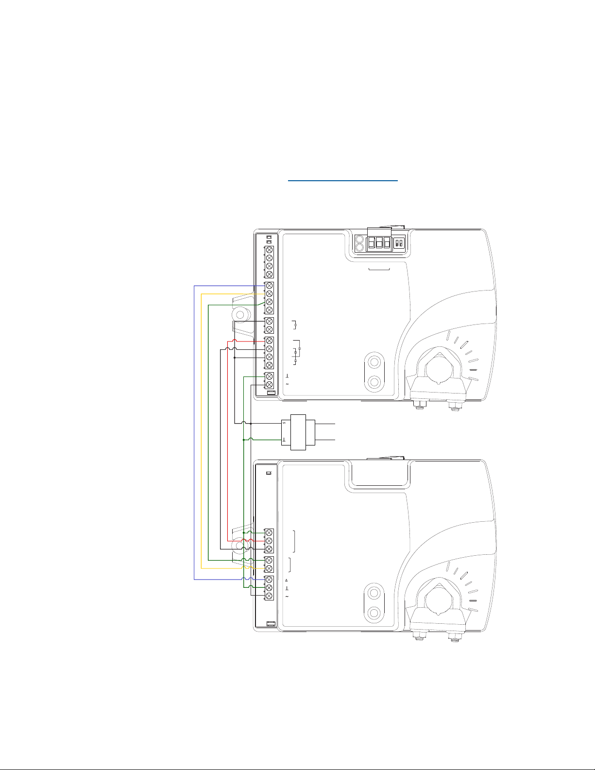
Dual-duct
application
This application is for a BAC-8007 controller. The controller is configured for
dual-duct operation. Dual-duct VAV requires a TSP-8001 actuator to be used
with the BC-8007 as shown in the illustration Dual-duct wiring diagram on
page 55.
Submittal sheets for several variations of this application are available from
the Resources page at www.SimplyVAV.com.
Illustration 6–6 Dual-duct wiring diagram
Revision E 55
Page 56

Section 6: Application drawings SimplyVAV
56 Revision E
Page 57

SimplyVAV
S e c t i o n 7 : Se qu e n c e s o f o pe r a tio n
Topics in this section cover the sequences of operation for the
SimplyVAV controllers. These are advanced topics for control technicians
and engineers.
These sequences of operation are descriptions of each major component of the
SimplyVAV programming. They are provided as an aid to understanding on
how the controllers operate.
This section covers the following sequences of operation.
Input sources
Occupancy sequence
Space setpoints
PID control loops
Airflow setpoints sequence
Changeover
Discharge Air Temperature (DAT) limiting
System diagnostics
Damper operation
Fan operation
Reheat sequence
Balancing airflow sequence
Dual duct
58
59
60
61
61
62
62
64
65
65
66
69
69
Revision E 57
Page 58

Section 7: Sequences of operation SimplyVAV
Input sources
The SimplyVAV controllers require specific sensors to measure room
temperature, airflow, and discharge air temperature. All sensors are
automatically detected and the programming is automatically set up for the
sensors.
SimplyVAV digital wall sensors
STE-6000 series thermistor temperature sensors
Discharge air temperature sensor
Airflow sensors and pickups
SimplyVAV digital wall sensors—The SimplyVAV digital wall sensors
include a room temperature sensor, a digital display, and a push button
interface for entering setpoints and configuring the controllers. If a
SimplyVAV digital wall sensor is detected, the sensor's temperature is
mapped to the Space Temperature Reference value object as the temperature
input value. See the topic BACnet objects on page 77 for additional
information on value objects.
The model BAC-8201 SimplyVAV digital wall sensor includes also a motion
sensor to detect when the zone is temporary unoccupied. This is described in
the topic Occupancy sequence on page 59.
STE-6000 series thermistor temperature sensors—There are three models
of the STE-6000 series sensors compatible with the SimplyVAV controllers. If
one of the three sensors is detected, the sensor's temperature is mapped to
the Space Temperature Reference value object as the temperature input value.
See the topic BACnet objects on page 77 for additional information on value
objects.
The STE-6014 and STE-6017 includes also a dial for adjusting the zone
setpoint. If either of these two sensors is detected, the space setpoint is
determined directly from the setting of the dial on the sensor.
The STE-6017 includes a button that when pushed will override the
unoccupied state. This is described in the topic Occupancy sequence on page
59.
Discharge air temperature sensor—The DAT sensor is an optional Type-III,
10 kΩ thermistor and is required for VAV heating applications. If the
controller detects that this sensor is connected, then the controller will use
discharge air temperature to determine when to change between heating and
cooling. The DAT sensor input is used also to control reheat. See the topics
Discharge Air Temperature (DAT) limiting on page 62 and Changeover on page
62.
Airflow sensors and pickups—VAV airflow is calculated by measuring the
high and low duct pressures with the built-in airflow sensor which is
connected to airflow pickup tubes. The high and low pressure measurements
58 Revision E
Page 59

SimplyVAV Section 7: Sequences of operation
along with the K-factor of the VAV terminal unit are used to calculate the
airflow through the VAV unit.
Occupancy sequence
A SimplyVAV controller is designed to operate as a stand-alone controller
and determine occupancy based only on the availability of primary airflow
and motion in the zone. The controller can be in any one of the following
occupancy states.
Occupied on page 59
Unoccupied
Standby
Occupancy can also be commanded by another BACnet device or an operator
workstation connected the building automation network. See the topic System
integration and networking on page 71 for details.
Automatic occupancy
If Automatic Occupancy is enabled, the controller will automatically toggle
between Unoccupied, Occupied, and Standby based on the presence of primary
airflow and motion in the zone.
The default for Automatic Occupancy is Disabled. See the topic Advanced
options on page 37 to change Automatic Occupancy.
Occupied
For controllers without a connected motion sensor, the controller changes to
Occupied upon the detection of primary airflow.
Controllers with a connected motion sensor change to Occupied upon the
detection of primary airflow and motion in the space. The unit will remain in
the Occupied state as long as periodic motion is detected and primary airflow
continues. If motion stops, the controller changes to Standby.
Unoccupied
The controller Occupancy mode changes to Unoccupied when it detects a loss
of primary airflow. While in the Unoccupied state, the controller will fully
open the damper in an attempt to reach the maximum airflow setpoint.
Loss of primary airflow is defined as less than 25% of the requested flow for
at least 5 minutes. The Occupancy mode changes to Occupied or Standby once
the actual airflow is at least 30% of the requested flow.
Standby
In units with a connected motion sensor, the controller starts in Standby and
changes to Occupied after detecting motion in the space. Motion in the space is
Revision E 59
Page 60

Section 7: Sequences of operation SimplyVAV
defined as two movements detected within 5 minutes. The controller will
change back to Standby after a lack a lack of motion for the period specified
by the variable Standby Time.
Standby mode is not valid for controllers without a motion sensor, unless
commanded by a building management system.
Space setpoints
There are four temperature setpoints each for heating and cooling for a total
of eight setpoints.
Active cooling
Occupied cooling
Unoccupied cooling
Standby cooling
Active heating
Occupied heating
Unoccupied heating
Standby heating
Types of setpoints
The SimplyVAV controllers may use any of the following setpoints based on a
user entered setpoint or the state of occupancy and standby which is
described in the topic Occupancy sequence on page 59.
Active setpoint—The active setpoint is the current setpoint. The active
setpoint is determined by the following.
If the space is occupied, the controller uses the occupied setpoint as the
active setpoint.
If the space is unoccupied the controller uses the unoccupied setpoint as
the active setpoint.
If controller occupancy is Standby, the controller calculates the standby
setpoint.
A user with Password 1 can enter an active setpoint from a SimplyVAV
digital wall sensor. This entry will change the occupied setpoint within
the setpoint limits.
If a sensor with a dial setpoint is connect to the controller, the dial
position is used for the active setpoint only when the Occupancy stae is
Occupied.
Occupied setpoint—A temperature setpoint entered by the controls
technician during controller setup and system commissioning. This is the
setpoint used when the controller is occupied which is determined by
primary airflow and, on controllers equipped with motion sensors, motion in
the zone.
Unoccupied setpoint—A temperature setpoint entered by the controls
technician during controller setup and system commissioning. This is the
setpoint used when the system is unoccupied .
60 Revision E
Page 61

SimplyVAV Section 7: Sequences of operation
Standby setpoint—The standby setpoint is used when the controller is in the
standby state. It is a value calculated from the occupied setpoint and the value
of Standby Offset. The standby offset value is entered by the controls
technician during controller setup and system commissioning. See the topic
Occupancy sequence on page 59.
Setpoint limits
The programming in the SimplyVAV controller limits the setpoint entry so
that no heating setpoint is set higher than its corresponding cooling setpoint.
If a user is adjusting a setpoint and it falls within the range set by the value of
Minimum Setpoint Differential, the corresponding setpoint will be changed to
maintain the differential. For example, the Minimum Setpoint Differential is
4°F and the Occupied Heating setpoint is 70°F. If the user lowers the
Occupied Cooling setpoint to 71°F, the controller recalculates the Occupied
Heating setpoint and changes it to 67°F.
PID control loops
Airflow setpoints sequence
A PID control loop calculates an error value from the difference between the
measured room temperature and the active setpoint. The error value is
expressed as a percentage and is typically used in a BAS controller to control
the state of an output. When the difference between the setpoint and room
temperature is large, the error is large. As the system reduces the difference
between the setpoint and space temperature, the error becomes smaller.
The SimplyVAV controllers use up to three PID loops.
The heating PID loop.
The cooling PID loop.
The discharge air temperature (DAT) loop.
For SimplyVAV controllers, the output of either the cooling and heating PID
loop is used to calculate the position of the damper. If present, the DAT input
and DAT loop controls the Reheat loop.
The PID loops in the SimplyVAV controllers are standard BACnetobjects and
are described in the topic BACnet objects on page 77.
Airflow Setpoint is calculated based on the demand for cooling or heating
depending on whether the Cooling loop or Heating loop is greater than zero.
If no room sensor is connected to the controller, the controller uses the
Minimum Cooling Airflow setpoint to maintain airflow.
Cool Air Sequence
Airflow Setpoint is proportionally calculated between Minimum Cooling
Airflow and Maximum Cooling Airflow.
Revision E 61
As the Cooling loop increases from 0% to 100%, Primary
Page 62

Section 7: Sequences of operation SimplyVAV
If there is a call for reheat to maintain room temperature, the primary airflow
is set to the value of Auxiliary Flow.
Changeover
Discharge Air Temperature (DAT) limiting
Warm Air Available
from 0% to 100%, Primary Airflow Setpoint is proportionally calculated
between Minimum Heating Airflow and Maximum Heating Airflow.
See also the topics, Changeover on page 62 and Input sources on page 58.
The Discharge Air Temperature input is used by the controller to determine
the type of air that is being supplied by the AHU. The sensor is required for
applications that require automatic change over between cooling and heating.
When the Heating loop is inactive, the Discharge Air Temperature input is
compared to the SAT Changeover Temp. If the Discharge Air Temperature is
below the SAT Changeover Temp minus 2°, the SAT Changeover Mode is set
to Cool. If the Discharge Air Temperature is above the SAT Changeover Temp
plus 2° Fahrenheit, the SAT Changeover Mode is set to Heat. The default
changeover temperature is 74° Fahrenheit.
See the topic Discharge Air Temperature (DAT) limiting on page 62 and Input
In the heating mode, as the Heating Loop increases
sources on page 58.
A Discharge Air Temperature senor and DAT limiting is required to control
VAV units with reheat. If a Discharge Air Temperature (DAT) sensor is
detected and DAT Limiting is enabled, the VAV terminal will be controlled
by the DAT loop. The unit will also limit the Discharge Air Temperature to
within 15° F of the Space Temp Reference.
When there is a call for heat and the primary air is cool air, the reheat outputs
are directly controlled by the DAT Loop and the DAT Setpoint reset based
on the output of the Heating loop. As the Heating loop increases from 0% to
50%, DAT Setpoint is proportionally calculated between Space Temp
Reference and Space Temp Reference + 15° F up to maximum 90° F. This
allows the reheat to be controlled by the DAT loop over the first 50% of a call
for heating.
62 Revision E
Page 63

HTG SP
HTG SPAN
50%
100%
0%
ROOM TMP
DAT loop
ROOM TMP+
15°
(Max 90°F)
SimplyVAV Section 7: Sequences of operation
Illustration 7–1 DAT limiting operation
If DAT Limiting is enabled, and a DAT sensor is not connected, the controller
will lockout reheat control only in the cooling mode. The unit will operate
this way until a DAT sensor is detected or until the unit is commanded to
control to the Active Heating Setpoint by a supervisory BMS.
If the unit has detected a DAT sensor and DAT Limiting is not enabled, the
unit’s reheat is controlled by the Heating loop instead of the DAT loop.
See also the topics Changeover on page 62 and Input sources on page 58.
Revision E 63
Page 64

Section 7: Sequences of operation SimplyVAV
System diagnostics
The controller programming includes four system diagnostic indicators in the
form of BACnet value objects.
Need for higher static pressure
Need for cooler supply air
Need for warmer supply air
Need AHU start
These diagnostic indicators or flags are monitored by other BACnet devices
connected to the same building automation system as the controller. How the
indicators are used is beyond the scope of these instructions.
Need for higher static pressure
The Need Higher Static value object is set to
True (1) when the damper is fully open and airflow cannot reach the required
setpoint value.
Need for cooler supply air
The Need Cooler Supply value object is set to
True (1) when the damper is fully open and the Cooling loop is greater than
95% for 30 minutes. The indicator changes to False (0) when the Cooling loop
falls below 90%.
Need for warmer supply air
The Need Warmer Supply value object is set to
True (1) when the damper is fully open and the Heating loop is greater than
95% for 30 minutes. The indicator changes to False (0) when the Heating loop
falls below 90%.
Need AHU start
of the following conditions.
The system mode is Unoccupied and the Cooling loop or the Heating
loop reaches 100%.
The system mode is Occupied.
The system mode is Standby.
The Need for AHU Start object changes to False (0) when both loops drop
below 5%.
The Need AHU Start value object is set to True (1) for any
64 Revision E
Page 65
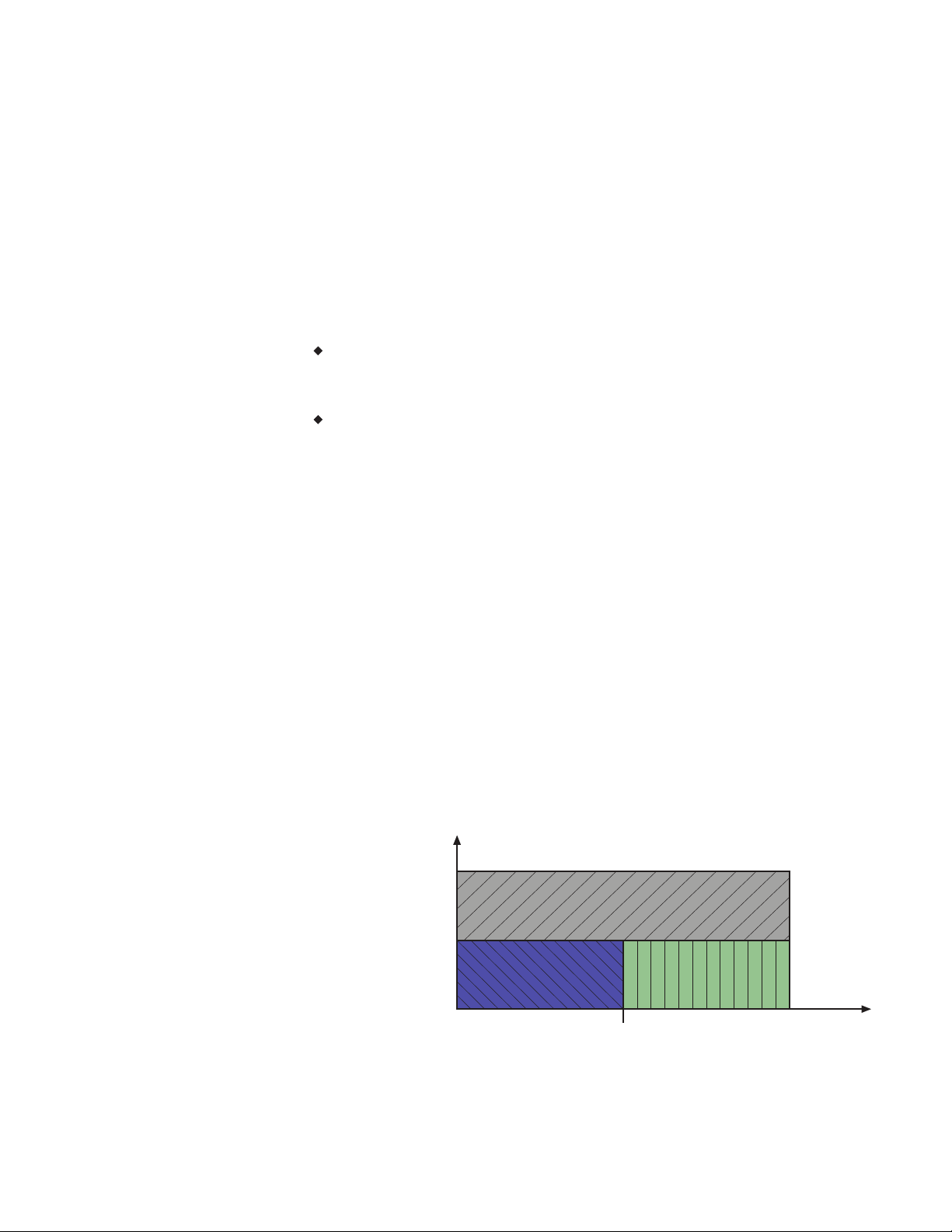
UNOCCUPIED/
STANDBY
STANDBY
MAX FAN SPEED
MIN FAN SPEED
FAN OFF
OCCUPIED
HTG SP ROOM TEMP INCREASE
SimplyVAV Section 7: Sequences of operation
Damper operation
Fan operation
Damper movement is determined by comparing the actual airflow reading to
the airflow setpoints. If the actual airflow is within 5% of the setpoint, no
damper action is initiated. Once within the 5% deadband, the actual airflow
must be outside a 7% deadband before damper position changes.
The SimplyVAV controllers support both series and parallel fan powered
VAV units. For either type of fan operation, the fan is controlled through the
following terminals.
A binary output triac controls a 24-volt fan starting circuit. See the topic
Configuring the VAV Box options on page 31 for the procedure to
configure the controller for a fan.
A 0-10 volt DC analog output controls the speed of the fan. The output
controls fan speed at either Min Fan Speed or Max Fan Speed. See the
topic Set the airflow setpoints on page 34 for the procedure to set the fan
speeds.
If the VAV unit is not configured for a fan, the two outputs are not used and
remain inactive regardless of the occupancy state.
Series Fan
If the controller is configured for a series fan, any time the Occupancy mode
of the controller is set to either Occupied or Standby, the fan runs
continuously. The fan speed is set to Maximum Fan Speed when the state is
Occupied and set to Minimum Fan Speed when the state is Standby.
Revision E 65
When the Occupancy state is Unoccupied, the fan starts and runs at minimum
speed only on a call for heating. The fan starts when the Heating loop is
greater than 5% and stops when the Heating loop is less than 1%.
Illustration 7–2 Series fan operation
Page 66
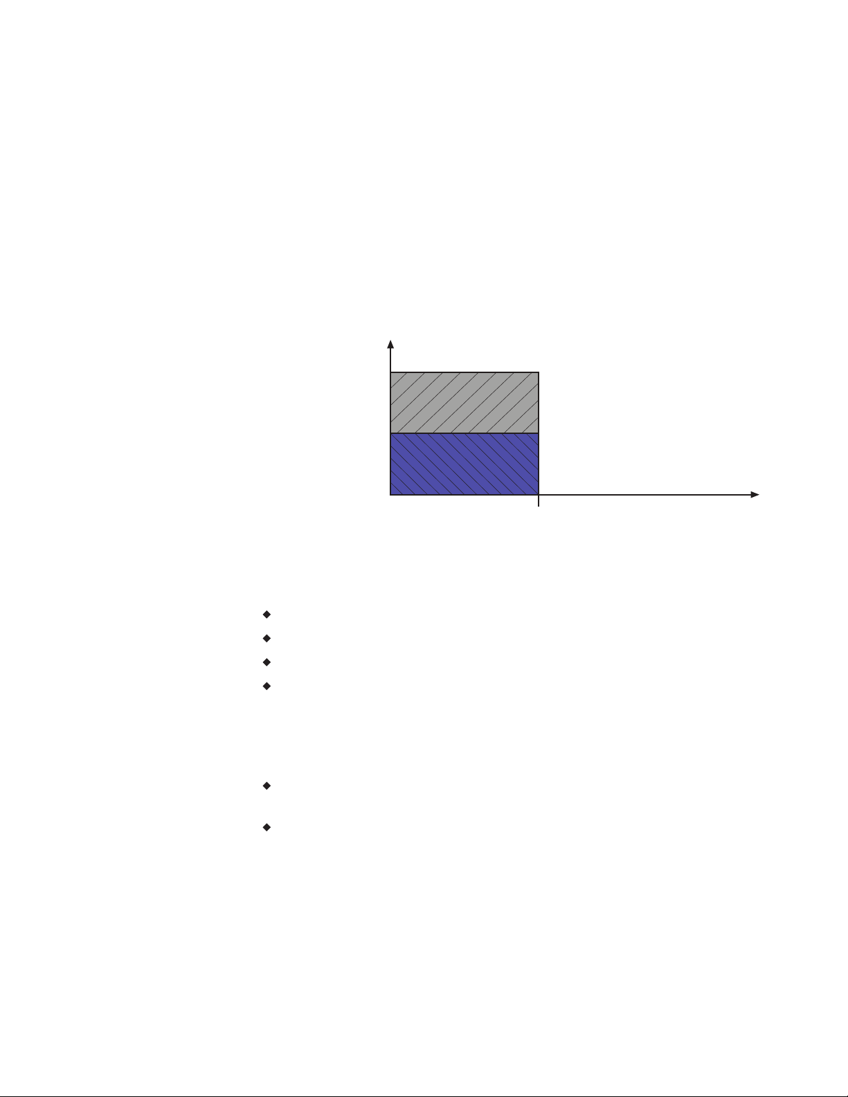
MAX FAN SPEED
MIN FAN SPEED
FAN OFF
OCCUPIED
HTG SP ROOM TEMP INCREASE
UNOCCUPIED/
STANDBY
Section 7: Sequences of operation SimplyVAV
Parallel Fan
If the controller is configured for a parallel fan, any time the Occupancy mode
of the controller is set to either Occupied or Standby and there is a call for
heat, the fan runs continuously. The fan starts when the Heating loop is
greater than 5% and stops when the Heating loop is less than 1%.
When the unit Occupancy state is Unoccupied, the fan starts and runs at
minimum speed only on a call for heating. The fan starts when the Heating
loop is greater than 5% and stops when the Heating loop is less than 1%.
Illustration 7–3 Parallel fan operation
Reheat sequence
The SimplyVAV controllers can control four types of reheat installations.
Modulating reheat
Staged reheat
Time proportioned reheat
Floating reheat
All reheat is controlled by either the Heating loop or the Discharge Air Temp
Limiting (DAT) PID loop. Loops are described in the topic PID control loops
on page 61.
If Discharge Air Temp Limiting is enabled, reheat is controlled by the
DAT PID loop.
If DAT control is not enabled, reheat is controlled by the Heating loop.
In the following descriptions, the loop controlling reheat is referred to as the
Reheat loop.
Modulating reheat
If the controller is configured for modulating reheat, it controls an analog
reheat unit with 0-10 volts DC at the analog reheat output. On a call for
66 Revision E
Page 67
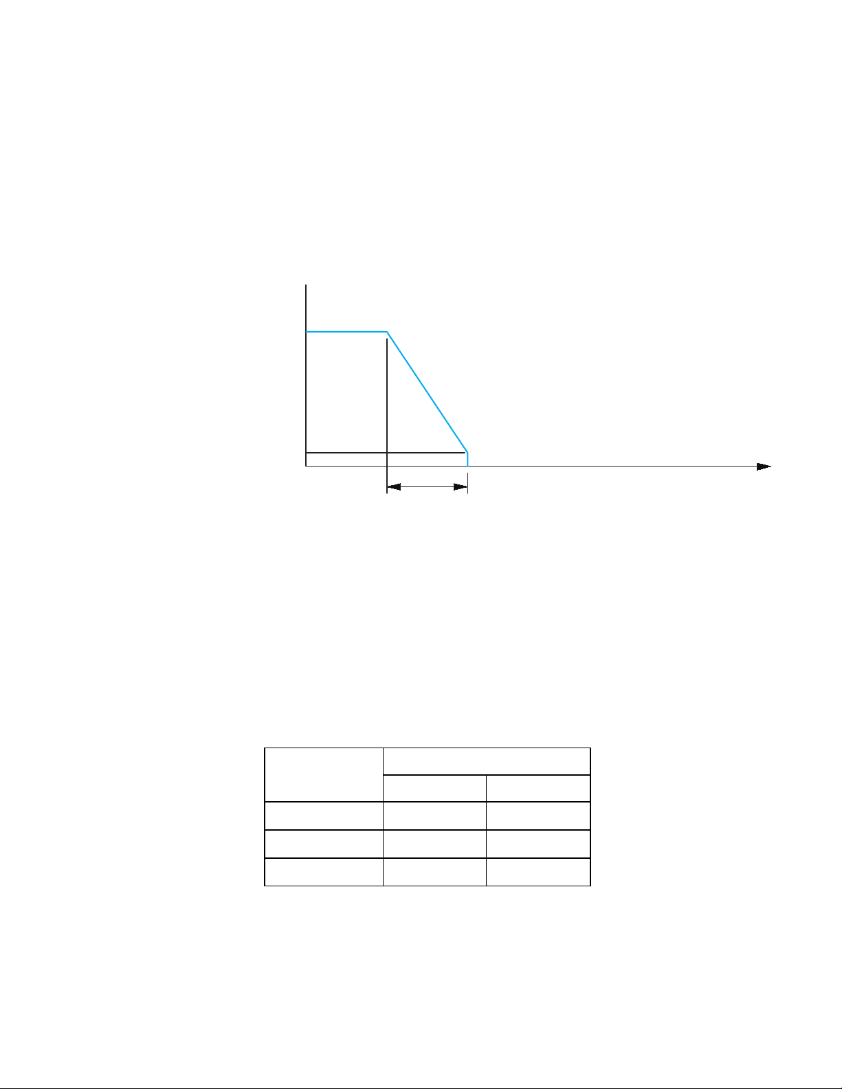
Room temp increase
HTG SP-2F
HTG SPAN
loop %
0
100
10
HTG %
Reheat
SimplyVAV Section 7: Sequences of operation
reheat, the reheat output is modulated over the span of the Reheat loop. If the
Reheat loop is less than 10%, the reheat output remains at zero. The reheat is
set to zero if the Cooling loop is active.
See the topic Modulating reheat on page 52 for an application drawing.
Illustration 7–4 Modulating reheat operation
Staged reheat
If the controller is configured for staged reheat, it can control up to three
stages of reheat through binary triac outputs. The reheat outputs are
commanded On when the Reheat loop rises above the On threshold and Off
when the loop drops below the Off threshold. Thresholds are described in the
following chart, Staged reheat thresholds on page 67.
See the topic Staged reheat on page 51 for an application drawing.
Table 7–1 Staged reheat thresholds
Output state
Heating stages
On threshold Off threshold
Stage 1 35% 15%
Stage 2 65% 45%
Stage 3 95% 75%
Time proportioned reheat
For controllers configured for time proportional reheat, the duty cycle of a
binary triac output varies over a 10 second period. For example, if the Reheat
Revision E 67
Page 68
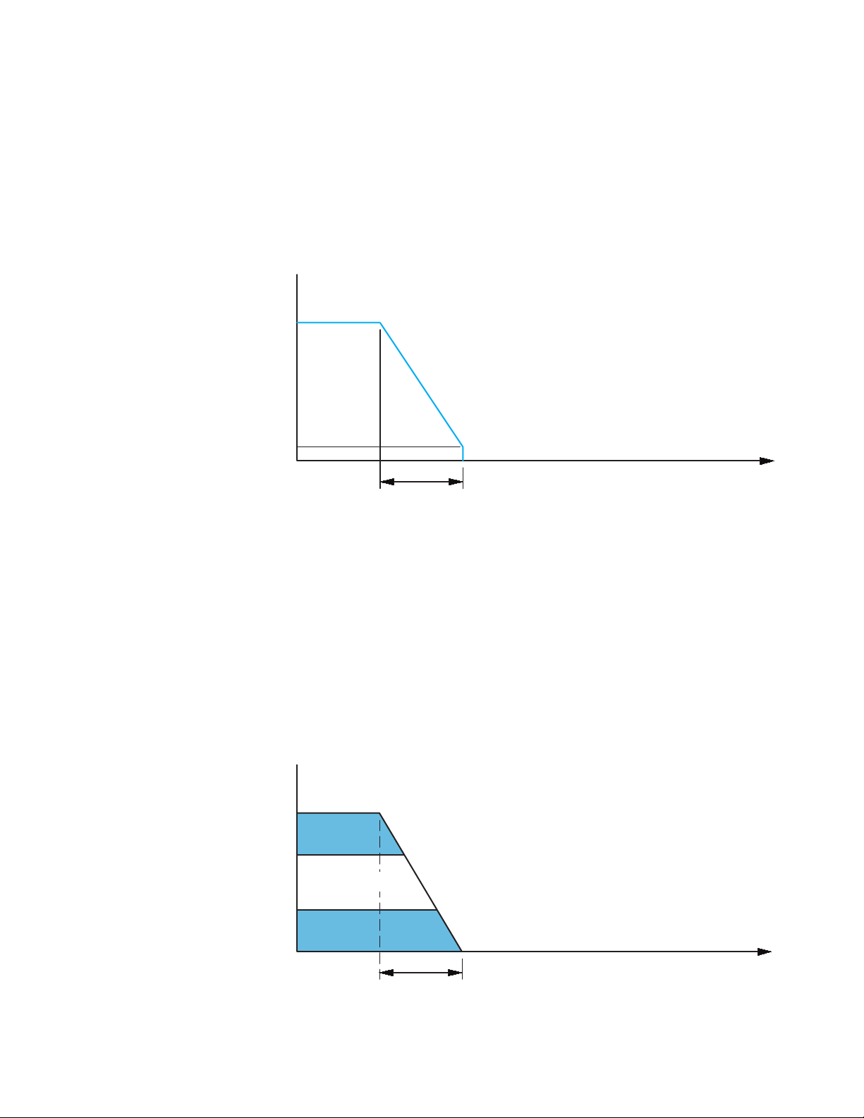
Room temp increase
HTG SP-2F
HTG SPAN
loop %
0
100
10
HTG %
Reheat
HTG %
DRIVE
OPEN
DRIVE
CLOSED
loop %
0
100
70
Reheat
30
HTG SP
HTG SPAN
-2F
Room temp increase
NO ACTION
Section 7: Sequences of operation SimplyVAV
loop is at 50%, the reheat output is On for 5 seconds and Off for 5 seconds. If
the Reheat loop is less than 10%, the reheat output remains at zero.
See the topic Time proportional reheat on page 53 for an application drawing.
Illustration 7–5 Time proportional reheat operation
Floating reheat
If the controller is configured for floating reheat, it controls two binary triac
outputs to drive the inputs of a tri-state actuator connected to a valve. If the
Reheat loop is less than 30%, the valve is driven closed. If the loop is greater
than 70%, the valve is driven open. If the loop is in between 30% and 70%, no
valve action is taken.
See the topic Floating reheat on page 54 for an application drawing.
Illustration 7–6 Floating reheat operation
68 Revision E
Page 69

SimplyVAV Section 7: Sequences of operation
Balancing airflow sequence
Balancing airflow is the process of calibrating the internal airflow sensor to a
known standard. In the field, airflow is measured with an airflow hood or
other measuring instrument and then compared to the airflow measurements
from the sensor in the controller. The balancing process uses an STE-8001 or
STE-8201 as the technicians setup tool for initiating the balancing sequence
and entering actual flow measurements.
When the balancing sequence starts, all other functions of the controller are
locked out.
At the start of the sequence, the controller drives the damper open until the
airflow reaches the highest value of either the cooling or heating maximum
airflow setpoints. An airflow measurement is made with an airflow hood and
the actual airflow value is entered into the controller. Once the actual airflow
is entered, the controller drives the damper closed to the lower value of
either the cooling or heating minimum airflow. Another measurement is made
with the flow hood and that measurement is entered into the controller.
After the minimum airflow measurement is entered, the programming in the
controller calculates airflow correction factors which are used to adjust
measurements from the internal airflow sensor. Balancing is complete and the
controller is returned to normal operation.
See the topic Balancing airflow on page 43 for the procedure to balance the
airflow with an STE-8001.
Dual duct
A dual duct installation consists of separate primary heating and cooling
ducts, both with control dampers and airflow monitoring. For this type of
installation a SimplyVAV BAC-8007 controls the cooling air (primary) damper
and a TSP-8001 actuator controls the heating air (secondary) damper.
As the space temperature rises above the cooling setpoint, the primary
airflow is modulated from the Cooling Minimum flow to the Cooling
Maximum Flow.
As the space temperature falls below the heating setpoint, the secondary
airflow is modulated from the Heating Minimum flow to the Heating
Maximum Flow.
Between the heating and cooling setpoints, both the primary airflow and
secondary airflow are modulated to maintain the Dual Duct Minimum
airflow.
See the topic, Dual-duct application on page 55 for an application drawing.
Revision E 69
Page 70
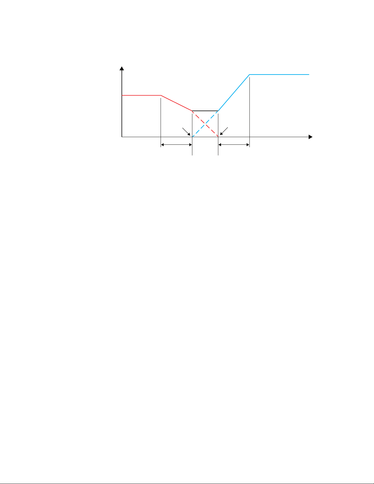
Max. cooling airflow
Airflow increase
Max heating airflow
Dual duct
minimum
airflow
Room temp increase
HTG SPAN CLG SPAN
HTG SP CLG SP
MIN
CLG
CFM
MIN
HTG
CFM
Section 7: Sequences of operation SimplyVAV
Illustration 7–7 Dual duct sequence
70 Revision E
Page 71

SimplyVAV
S e c t i o n 8 : Sy st e m in te g r at io n a n d ne tw o r k in g
Topics in this section cover integrating the controllers into a building
automation network. These are advanced reference topics for control
technicians and engineers.
The controllers can be installed as standalone controllers or they can be
connected to a BACnet MS/TP network. The topics in this section are
reference material for control technicians or engineers who are planning,
installing, and setting up controllers that are connected to a network.
In addition to the information in this section, you will also need the following
information.
Detailed plans and drawings for the building automation system.
Information about the facility LAN including routers, switches, and
network firewalls.
Sequences of operation for other BACnet devices that will monitor or
interact with SimplyVAV controllers.
Integration topics
Connecting to an MS/TP network
Setting up network communications
BACnet objects
72
75
77
Revision E 71
Page 72
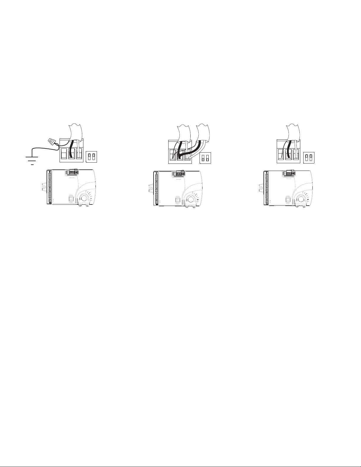
ONCTS
1 2
COMM
READY
AI1
AI5
GND
AO4
AO3
SC
BO8
BO5
BO6
SC
BO7
24VAC
AI6
GND
AI7
T-STAT/
SENSOR
-A
+B
S
EOL
BACnet MS/TP
S
+B
-A
ON
1 2
ONCTS
1 2
COMM
READY
AI1
AI5
GND
AO4
AO3
SC
BO8
BO5
BO6
SC
BO7
24VAC
AI6
GND
AI7
T-STAT/
SENSOR
-A
+B
S
EOL
BACnet MS/TP
S
+B
-A
ON
1 2
ONCTS
1 2
COMM
READY
AI1
AI5
GND
AO4
AO3
SC
BO8
BO5
BO6
SC
BO7
24VAC
AI6
GND
AI7
T-STAT/
SENSOR
-A
+B
S
EOL
BACnet MS/TP
S
+B
-A
ON
1 2
End of line controller
with grounded shield
EOL switches ON
Mid line controller
EOL switches OFF
End of line controller
with open shield
EOL switches ON
Section 8: System integration and networking SimplyVAV
Connecting to an MS/TP network
SimplyVAV controllers are BACnet MS/TP compliant controllers. Connect
them only to a BACnet MS/TP network.
To enter the BACnet device instance, MAC address, and network baud, see
the topic Setting up network communications on page 75.
Illustration 8–1 MS/TP network wiring and EOLswitches
Connections and wiring
Use the following principles when connecting a controller to an MS/TP
network:
72 Revision E
Page 73

SimplyVAV Section 8: System integration and networking
Connect no more than 128 addressable BACnet devices to one MS/TP
network. The devices can be any mix of controllers or routers.
To prevent network traffic bottlenecks, limit the MS/TP network size to
60 controllers.
Use twisted pair, shielded cable with capacitance of no more than
51picofarads per foot for all network wiring. Belden cable model #82760
meets the cable requirements.
Connect the -A terminal in parallel with all other - terminals.
Connect the +B terminal in parallel with all other + terminals.
Connect the shields of the cable together at each mid line controller. For
SimplyVAV controllers use the S terminal.
Connect the shield to an earth ground at one end only.
Use a KMD–5575 repeater between every 32 MS/TP devices or if the
cable length will exceed 4000 feet (1220 meters). Use no more than four
repeaters per MS/TP network.
Place a KMD–5567 surge suppressor in the cable where it exits a
building.
End of line termination switches
The controllers on the physical ends of the EIA-485 wiring segment must
have end of line termination added for proper network operation.
For controllers at the end of the network set the EOL switches to On
For mid line controllers at the end of the network set the EOL switches
to Off
Network bulbs
SimplyVAVcontrollers include network bulbs located near the MS/TP
network connector. These bulbs serve three functions:
Removing both bulbs will disconnect the controller from the MS/TP
network.
If one or both bulbs are lit, it indicates the network connection or
controller power is not properly wired.
If the voltage or current on the network exceeds safe levels, the bulbs
may open and protect the controller from damage.
Bulbs are illuminated
network is not phased correctly. The ground potential of the controller is not
the same as other controllers on the network. The brighter the isolation bulbs
on a controller are illumniated, the closer that controller is to the source of
the problem. Remove power and check the network and power connections.
If one or both bulbs are illuminated, it indicates the
Revision E 73
Page 74

Section 8: System integration and networking SimplyVAV
Bulbs are open
meter—it indicates the voltage or current on the network exceeded safe
levels. Correct the conditions and replace the bulbs.
Bulbs not inserted correctly
inserted into the socket.
If one or both bulbs are open—as tested with an ohm
One lead from one or both of the bulbs are not
74 Revision E
Page 75
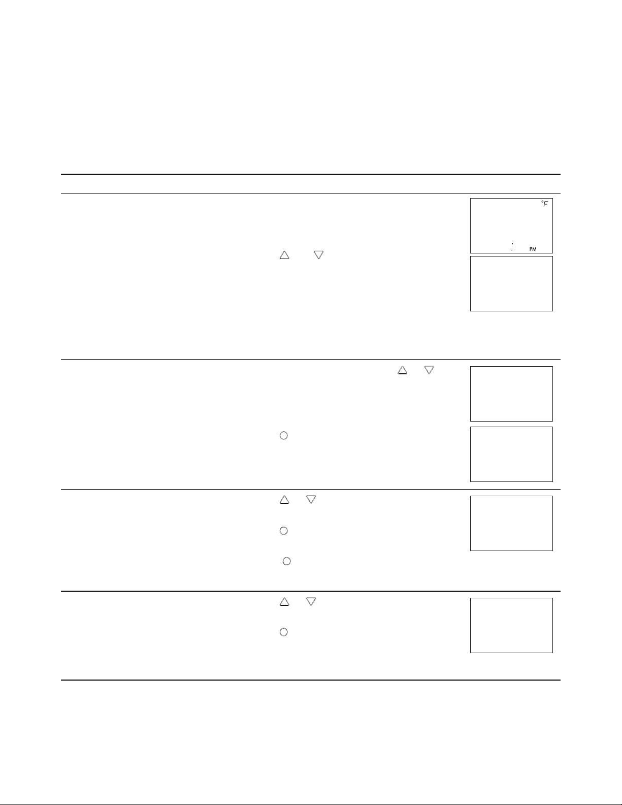
72
12S1
PSW2
OOOO
Set
Point
CNFG
COMM
Set
Point
Set
Point
D ID
OO72O69
Set
Point
MAC
11
SimplyVAV Section 8: System integration and networking
Setting up network communications
Table 8–1 Procedure to set up network communications
Set the network communication settings before placing a controller on the
network. Setting network settings requires entering Password 2 which is
described in the topic Getting started with configuration on page 26.
Procedure Detailed steps STE display
1.
1 Starting display
2 Select the CNFG display
Start at the temperature display.
2.
Press the and buttons together.
l If Password 2 is not required, the display
changes to CNFG.
l If required, enter Password 2. The display
changes to CNFG when Password 2 is
correct.
1.
From the CNFG display, press the or
buttons to advance to the COMM display.
3 Enter the device instance.
4 Enter the MAC address.
2.
Press the
button. The display changes to
DID.
1.
Press the or buttons to change the first
digit.
2.
Press the
Repeat for all seven digits.
3.
When the
digit, the display changes to MAC.
1.
Press the or buttons to change the MAC
address.
2.
Press the
address.
The display changes to BAUD.
button to select the next digit.
button is pressed for the last
button to save the selected MAC
Revision E 75
Page 76

Set
Point
BAUD
384OO
Set
Point
COMM
Section 8: System integration and networking SimplyVAV
Procedure to set up network communications (continued)
Procedure Detailed steps STE display
1.
5 Enter the baud
Press the or buttons to select a new baud.
2.
Press the
button is save the selected baud.
The display returns to COMM.
1.
6 Advance or exit
Press the or buttons to select one of the
following:
BLNC or CNFG options
EXIT to return to the temperature display.
2.
Press the
button to select the next function.
76 Revision E
Page 77

Caution
SimplyVAV Section 8: System integration and networking
BACnet objects
The SimplyVAV controllers are BACnet Application Specific Controller (ASC)
that are composed of standard BACnet objects. This section lists the objects
that are likely to be monitored by a standard BACnet operator workstation
to verify system operation.
Changing the configuration of any object may result in
unpredictable operation of a controller and damage to
equipment that is under control of a SimplyVAV controller.
Input objects
The following BACnet input objects represent values at the physical inputs of
the controller. For wiring details, see the topic Application drawings on page
49.
Table 8–2 Input objects
Input Name Description Object type
AI1 DISCHARGE AIR Discharge Air Temperature KMC10K_Type_III
AI2 SPACE SENSOR Space Sensor KMC Type II Deg F
AI3 SPACE
SETPOINT
AI4 PRIMARY DUCT Primary Duct Pressure
AI5 SECONDARY
DUCT
Space Setpoint TABLE_4
Secondary Duct Pressure
Output objects
The following BACnet output objects represent values at the physical outputs
of the controller. For application specific output wiring details, see the topic
Application drawings on page 49.
Table 8–3 Output objects
Output Name Description Units
AO3 ANALOG HEAT Analog Heat 0_100%
Revision E 77
Page 78

Section 8: System integration and networking SimplyVAV
Output objects (continued)
Output Name Description Units
AO4 FAN SPEED Fan Speed 0_100%
BO1 DAMPER CW Damper Clockwise
BO2 DAMPER CCW Damper Counter Clockwise
BO5 FAN Fan
BO6 HT STAGE 1 Heating Stage 1
BO7 HT STAGE 2 Heating Stage 2
BO8 HT STAGE 3 Heating Stage3
Value objects
BACnet value objects represent setpoints or other operational conditions in
the controller.
Note: Not all objects are present in every model.
Table 8–4 Analog value objects
Object Name Description
AV1 SPACE TEMP Space Temperature
AV2 STPT REFERENCE Setpoint Reference
AV3 ACT COOL STPT Active Cooling Setpoint
AV4 ACT HEAT STPT Active Heating Setpoint
AV5 OCC CL STPT Occupied Cooling Setpoint
AV6 OCC HT SPT Occupied Heating Setpoint
AV7 UNOCC CL STPT Unoccupied Cooling Setpoint
AV8 UNOCC HT STPT Unoccupied Heating Setpoint
AV9 MIN CL STPT Minimum Cooling Setpoint
AV10 MAX HT STPT Maximum Heating Setpoint
AV11 MIN STPT DIFF Minimum Setpoint Differential
AV12 STBY DIFF Standby Differential
AV13 MIN COOL FLOW Minimum Cooling Flow
78 Revision E
Page 79

SimplyVAV Section 8: System integration and networking
Analog value objects (continued)
Object Name Description
AV14 MAX COOL FLOW Maximum Cooling Flow
AV15 MIN HEAT FLOW Minimum Heating Flow
AV16 MAX HEAT FLOW Maximum Heating Flow
AV17 AUXILLARY FLOW Auxillary Flow
AV18 PRI K FACT Primary K Factor
AV19 PRI CORR SLOPE Primary Correction Slope
AV20 PRI CORR OFFST Primary Correction Offset
AV21 PRI LO FLOW CORR Primary Low Flow Correction
AV22 PRI FLOW STPT Primary Flow Setpoint
AV23 PRI RAW FLOW Primary Raw Flow
AV24 PRI ACTUAL FLOW Primary Actual Flow
AV32 MIN FAN SPEED Minimum Fan Speed
AV33 MAX FAN SPEED Maximum Fan Speed
AV36 DAT STPT Discharge Air Temp Setpoint
AV37 SAT CHANGEOVER SAT Changeover Temperature
AV38 LOCAL OVRD TIME Local Override Timer
AV39 STANDBY TIME Standby Timer (motion)
AV40 STANDBY TRIGGER Standby Trigger
AV43 MEASURED MAX Measured Maximum
AV44 MEASURED MIN Measured Minimum
AV45 PRI SAVE MIN FLO Primary Saved Minimum Airflow
AV47 DAT MAXIMUM Maximum DAT Setpoint
AV48 CW DMP POS CW Damper Position
AV49 CCW DMP POS CCW Damper Position
AV50 DAMPER POSITION Damper Position
AV55 CHNG_OVER_DELAY Cooling Change Over Delay
AV56 LOW AUTO OCC Low Limit for Auto Occupy
Revision E 79
Page 80

Section 8: System integration and networking SimplyVAV
Table 8–5 Binary value objcts
Object Name Description
BV1 NEED AHU Need For AHU
BV2 NEED COLDER SPLY Need For Colder Air Supply
BV3 NEED MORE STATIC Need For AHU
BV4 LOCAL OVRD Local Override Mode
BV5 MOTION OVRD Motion Override Mode
BV6 MOTION SENSOR Motion Sensor (Wall Stat)
BV7 NEED HOTTER SPLY Need For Hotter Air Supply
BV8 CHANGE OVER MODE SAT Changeover Mode
BV9 DAT LIMITING Discharge Air Temp Limiting
BV10 CLOCKWISE CLOSE Clockwise Close
BV11 AUTO OCCUPANCY Auto Occupancy Detection
BV12 BALANCE MODE Balance Mode
BV13 DAT SENSOR DAT Sensor Present
BV14 PRI BAL TRIGGER Primary Balance Trigger
Table 8–6 Multistate value objects
Object Name Description
MSV1 OCCUPIED MODE Occupied Mode
MSV2 FAN CONFIG Fantype Configuration
MSV3 REHEAT Reheat Type
MSV6 WALL SENSOR Multi-state Value #6
Loop objects
BACnet PID loops are used for modulating the damper and controlling
reheat.
Table 8–7 PID control loop objects
Loop Name Description
LOOP1 CL LOOP Cooling Loop
80 Revision E
Page 81

SimplyVAV Section 8: System integration and networking
PID control loop objects (continued)
Loop Name Description
LOOP2 HT LOOP Heating Loop
LOOP3 DAT Loop Discharge Air Temp Loop
Revision E 81
Page 82

Section 8: System integration and networking SimplyVAV
82 Revision E
Page 83

SimplyVAV Appendix A: K-factors
A p p e n d i x A : K -f ac to r s
To set up a VAV controller, a K-factor must be entered into the controller.
Typically, this is part of the airflow chart that the manufacturer places on the
VAV unit. If this information is missing and not available from the
manufacturer, use the K-factor in the following chart.
Table A–1 Start point K factors
Duct size in inches K-factor
4 265
5 357
6 460
7 652
8 890
9 1145
10 1143
12 1972
14 2771
16 3741
20 2106
22 2106
26 2498
40 7176
24 x 16 6980
Revision E 83
Page 84

Appendix A: K-factors SimplyVAV
84 Revision E
Page 85

SimplyVAV
In de x
A
accessories 11
actuator
mounting 17
rotation limits 16
shaft size 7
specifications 7
speed 7
airflow
balancing 43
maximum limit 34
minimum limit 34
sensor 18
setting limits 34
applications 49
cooling only without reheat 50
cooling/heating without reheat 50
dual duct 55
floating reheat 54
modulating reheat 52
staged reheat 51
three-stage reheat 51
time proportional reheat 53
automatic occupancy
enabling 37
sequence 59
auxillary flow
sequence 61
setting 34
B
BAC-8001
cooling only 50
cooling/heating 50
BAC-8005
floating reheat 54
modulating reheat 52
staged reheat 51
time proportional reheat 53
BAC-8007, dual-duct 55
BACnet objects 77
input 77
loops 80
outputs 77
PID loop sequence 61
value 78
balancing
procedure 43
sequence 69
baud 75
bulbs
network 72
replacement 11
C
calibration
airflow 43
sensors 37
Celsius display 40
changeover sequence 62
configuration 25
connecting
airflow sensor 18
DAT sensor 20
input devices 18
output devices 18
sensors 19
D
damper
sequence 65
setting direction to close 31
device instance 75
discharge air temperature
enabling 37
sensor connection 20
display units 40
dual duct
application drawing 55
sequence 69
E
end-of-line switches 72
end stops 16
English display 40
F
Fahrenheit display 40
Revision E 85
Page 86

Index SimplyVAV
fans
configuration 31
parallel sequence 65
series sequence 65
setting speed 34
speed sequence 65
with floating reheat 54
with modulating reheat 52
with staged reheat 51
with time proportional reheat 53
floating reheat 54
O
occupied
sequence 59
temperature setpoints 27
outputs
as BACnet objects 77
connecting 18
specifications 7
override
sequence 58
setting time 37
I
inputs
as BACnet objects 77
connecting 18
DAT sensor 20
room sensors 19
specifications 7
installing the controller 15
K
K-factor
setting 31
unknown 83
P
parallel fan
configuration 31
sequence 65
passwords
changing and establishing 37
Password 1 23
Password 2 26
PID loops
as BACnet objects 80
sequence of operation 61
R
M
MAC address 75
maintenance 22
Metric display 40
models 12
modulating reheat 52
motion sensing sequence 59
mounting 17
MS/TP wiring 72
N
network
address 75
baud 75
bulbs 72
termination 72
wiring 72
reheat
configuration 31
floating 54
modulating 52
sequences of operation 66
staged 51
three-stage 51
time proportional 53
two-stage 51
replacement parts 11
restore application 40
rotation limits 16
S
sensors
airflow 18
calibration 37
compatible 11
connecting 19
DAT sensor 20
86 Revision E
Page 87

SimplyVAV Index
room sensors 19
sequence 58
sequences of operation 57
airflow setpoints 61
balancing 69
changeover 62
damper 65
DAT limiting 62
dual duct 69
fans 65
input sources 58
motion detection 59
occupancy 59
PID loops 61
sensors 58
setpoints 60
standby 59
system diagnostics 64
unoccupied 59
series fan 65
configuration 31
sequence 65
setpoints
limits sequence 60
room temperature sequence 60
sequence 60
setting
changeover 27
limits 27
occupied 27
room 23
standby 27
shaft size for actuator 7
specifications 7
standby
sequence 59
setting timer 37
submittal sheets 49
system diagnostics 64
tri-state reheat 54
two-stage reheat 51
U
units to display 40
unoccupied
sequence 59
temperature setpoints 27
V
value objects 78
W
wiring
application drawings 49
connecting power 21
DAT sensor 20
MS/TP network 72
room sensors 19
T
three-stage reheat 51
time proportional reheat 53
timers, setting 37
transformer wiring 21
Revision E 87
Page 88

Index SimplyVAV
88 Revision E
 Loading...