

Page 1
Installation and Operation Guide
BAC-7302 and BAC-7302C
Advanced Applications Controller
Section 1
About the BAC-7302
Specifications ........................................................................................................................ 3
Accessories ............................................................................................................................ 6
Safety considerations ..........................................................................................................7
Section 2
Installing the controller
Mounting .............................................................................................................................. 9
Connecting inputs ............................................................................................................... 9
Connecting outputs ........................................................................................................... 10
Connecting to a NetSensor ............................................................................................... 11
Connecting to an MS/TP network .................................................................................. 11
Connecting power ............................................................................................................. 13
Programming ..................................................................................................................... 14
Section 3
Operating the controller
Operation ............................................................................................................................ 15
Controls and Indicators .................................................................................................... 15
Restoring factory settings ................................................................................................. 18
905-019-53FRevision F
Page 2

KMC Controls
Important notices
©2013, KMC Controls, Inc.
WinControl XL Plus, NetSensor, and the KMC logo are registered trademarks of KMC Controls, Inc.
BACstage and TotalControl are trademarks of KMC Controls, Inc.
MS/TP automatic MAC addressing is protected under United States Patent Number 7,987,257.
All rights reserved. No part of this publication may be reproduced, transmitted, transcribed, stored in a
retrieval system, or translated into any language in any form by any means without the written permission of
KMC Controls, Inc.
Printed in U.S.A.
Disclaimer
The material in this manual is for information purposes only. The contents and the product it describes are
subject to change without notice. KMC Controls, Inc. makes no representations or warranties with respect to
this manual. In no event shall KMC Controls, Inc. be liable for any damages, direct or incidental, arising out of
or related to the use of this manual.
KMC Controls
P. O . B o x 4 9 7
19476 Industrial Drive
New Paris, IN 46553
U.S.A.
TEL: 1.574.831.5250
FAX: 1.574.831.5252
E-mail: info@kmccontrols.com
Revision F2
Page 3

BAC-7302 RTU Controller
SECTION 1
About the BAC-7302
This section provides a general description of the KMC Controls
BAC-7302 controller. It also introduces safety information. Review
this material before installing or operating the controller.
The BAC-7302 is a native BACnet, fully programmable controller designed for roof
top units. Use this versatile controller in stand-alone environments or networked to
other BACnet devices. As part of a complete facilities management system, the
BAC-7302 controller provides precise monitoring and control of connected points.
◆ BACnet MS/TP compliant
◆ Automatically assigns the MAC address and the device instance
◆ Triac outputs for fan control, two-stage heating and two-stage cooling
◆ Supplied with programming sequences for roof top units
◆ Easy to install, simple to configure, and intuitive to program
◆ Controls room temperature, humidity, fans, monitors refrigeration, lighting,
and other building automation functions.
Specifications Inputs
Universal inputs 4
Key features Software selectable as analog, binary or accumulator
Pull–up resistors Switch select none or 10k.
Connector Removable screw terminal block, wire size
Conversion 10–bit analog–to–digital conversion
Pulse Counting Up to 16 Hz
Input range 0–5 volts DC
NetSensor Compatible with models KMD–1161 and KMD–1181.
Outputs, Universal 1
Key features Output short protection
Connector Removable screw terminal block
Output voltage 0–10 volts DC analog
Output current 100 mA per output
objects. Accumulators limited to three in one
controller.
Standard units of measure.
NetSensor compatible
Overvoltage input protection
AWG
14–22
Programmable as an analog or binary object.
Standard units of measure
Wire size 14-22 AWG
0–12 volts DC binary output range
Revision F 3
Page 4

About the BAC-7302
Specifications
KMC Controls
Outputs, Single-stage triac 1
Key features Optically isolated triac output.
Programmable a binary object.
Connector Removable screw terminal block
Wire size 14-22 AWG
Output range Maximum switching 30 volts AC at 1 ampere
Outputs, Dual-stage triac 2
Key features Optically isolated triac output.
Programmable as binary object.
Connector Removable screw terminal block
Wire size 14-22 AWG
Output range Maximum switching 30 volts AC at 1 ampere
Communications
BACnet MS/TP EIA–485 operating at rates up to 76.8 kilobaud.
Automatic baud detection.
Automatically assigns MAC addresses and device
instance numbers.
Removable screw terminal block.
Wire size 14–22 AWG
NetSensor Compatible with models KMD–1161 and KMD–1181,
Connects through RJ–12 connector.
Programmable features
Control Basic 10 program areas
PID loop objects 4 loop objects
Value objects 40 analog and 40 binary
Time keeping Real time clock with power backup for 72 hours
(BAC-7302-C only)
See PIC statement for supported BACnet objects
Schedules
Schedule objects 8
Calendar objects 3
Trend objects 8 objects each of which holds 256 samples
Alarms and events
Intrinsic reporting Supported for input, output, value, accumulator,
trend and loop objects.
Notification class objects 8
MemoryPrograms and program parameters are
stored in nonvolatile memory.
Auto restart on power failure
4
Revision F
Page 5

BAC-7302 RTU Controller
About the BAC-7302
Specifications
Application programs KMC Controls supplies the BAC-7302 with
programming sequences for roof top units:
◆ Roof top operation based on occupancy, night
setback, proportional hot and chilled water valve
control.
◆ Economizer operation.
◆ Freeze protection.
Regulatory UL 916 Energy Management Equipment
FCC Class B, Part 15, Subpart B
BACnet Testing Laboratory listed
CE compliant
SASO PCP Registration KSA R-103263
Environmental limits
Operating 32 to 120° F (0 to 49° C)
Shipping –40 to 140° F (–40 to 60° C)
Humidity 0–95% relative humidity (non-condensing)
Installation
Supply voltage 24 voltsAC(–15%,+20%),50‐60Hz,8VA
minimum,15VAmaximumload,Class2only,
non‐supervised(allcircuits,includingsupply
voltage,arepowerlimitedcircuits)
Weight 8.2 ounces (112 grams)
Case material Flame retardant green and black plastic
Models
BAC-7302C BACnet RTU controller with real-time clock
BAC-7302 BACnet RTU controller without real-time clock
Revision F
5
Page 6
About the BAC-7302
OUT4 GND T3B RTN3 T3A T2B RTN2 T2A RTN1 T1
A
E
B
C
D
Accessories
KMC Controls
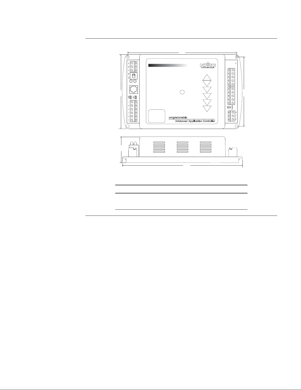
Dimensions
Table 1-1 BAC-7302 Dimensions
A B C D E
4.36 in. 6.79 in. 1.42 in. 4.00 in. 6.00 in.
111 mm 172 mm 36 mm 102 mm 152 mm
Accessories Power transformer
XEE-6111-40 Single-hub 120 volt transformer
XEE-6112-40 Dual-hub 120 volt transformer
6
Revision F
Page 7

BAC-7302 RTU Controller
Danger
Warning
Caution
Note
Detail
Safety considerations
About the BAC-7302
Safety considerations
KMC Controls assumes the responsibility for providing you a safe product and
safety guidelines during its use. Safety means protection to all individuals who
install, operate, and service the equipment as well as protection of the equipment
itself. To promote safety, we use hazard alert labeling in this manual. Follow the
associated guidelines to avoid hazards.
Danger represents the most severe hazard alert. Bodily harm or death will
occur if danger guidelines are not followed.
Warning represents hazards that could result in severe injury or death.
Caution indicates potential personal injury or equipment or property damage
if instructions are not followed.
Notes provide additional information that is important.
Provides programing tips and shortcuts that may save time.
Revision F
7
Page 8

About the BAC-7302
Safety considerations
KMC Controls
8
Revision F
Page 9

BAC-7302 RTU Controller
Note
OUT4 GND T3B RTN3 T3A T2B RTN2 T2A RTN1 T1
1
BAC-7302 cover removed.
Off On
SECTION 2
Installing the controller
This section provides a brief overview of the BAC-7302 and the
BAC-7302C Direct Digital Controllers. Review this material before
you attempt to install the controller.
Mounting Mount the controller inside of a metal enclosure. KMC Controls recommends using
a UL-approved Enclosed Energy Management Equipment Panel such as a KMC
model HCO–1034, HCO–1035 or HCO–1036. Insert #6 hardware through the four
mounting holes on the top and bottom of the controller to securely fasten it to a flat
surface. See
maintain RF emission specifications, use either shielded connecting cables or enclose
all cables in conduit.
Dimensions on page 6 for mounting hole locations and dimensions. To
Connecting inputs The BAC-7302 controller has four universal inputs. Each input can be configured to
receive either analog or digital signals. By using the optional pull-up resistors, either
passive or active devices may be connected to the inputs.
KMC supplied Control Basic programs assign input 1 (I1) to the space
temperature sensor input. If the KMC programs are not in used or are
modified, input 1 is available for other use. Inputs 2 and 3 are not assigned by
KMC programs and are available as needed.
Pull–up resistors
For passive input signals, such as thermistors or switch contacts, use a pull-up
resistor. For KMC thermistors and most other applications set the switch to the On
position. See
Illustration 2-1 for the pull-up switch location.
Illustration 2-1 Pull-up resistors and input terminals
Revision F 9
Page 10

Installing the controller
Caution
OUT4 GND T3B RTN3 T3A T2B RTN2 T2A RTN1 T1
OUT4 GND T3B RTN3 T3A T2B RTN2 T2A RTN1 T1
Universal
output and
ground
Triac 2a and 2b
output and
return
Triac 3a and 3b
output and
return
Triac 1
output and
return
Connecting outputs
KMC Controls
4–20 mA inputs
To use a 4–20 current loop input, connect a 250 ohm resistor from an input to
ground. The resistor will convert the current input to a voltage which can be read by
the controller analog-to-digital converter. Set the pull-up switch to the
Off position.
Ground terminals
Input ground terminals are located next to the input terminals. Up to two wires, size
14–22 AWG, can be clamped into each ground terminal. If more than two wires must
be joined at a common point, use an external terminal strip to accommodate the
additional wires.
Pulse inputs
Connect pulse inputs under the following conditions:
◆ If the pulse input is a passive input such as switch contacts, then place the
input pull-up in the On position.
◆ If the pulse is an active voltage (up to a maximum of +5 volts DC ), then place
the input pull-up jumper in the Off position.
Connecting
outputs
The BAC-7302 includes one single-stage triac, two-three stage triacs and one
universal output. All triacs are rated for 24 volt, 1 ampere loads, switch on zero
crossing and are optically isolated.
Illustration 2-2 Output terminals
When connecting loads to triacs, use only the terminal marked RTN associated
with each triac for the 24-volt ciruit.
Output 1 This output a single triac is designed to switch a 24-volt AC fan motor
starter circuit.
Output 2 Typically programmed with a PID loop object to control two-stage
heating. Triac 2A turns on when the programmed output is above 40% and turns off
below 30%. Triac 2B turns on when the programmed output is above 80% and turns
off below 70%.
10
Revision F
Page 11

BAC-7302 RTU Controller
OUT4 GND T3B RTN3 T3A T2B RTN2 T2A RTN1 T1
75 feet Max.
Connecting to a NetSensor
Installing the controller
Connecting to a NetSensor
Output 3 Typically programmed with a PID loop object to control two-stage
cooling. Triac 3A turns on when the programmed output is above 40% and off below
30%. Triac 3B turns on when the programmed output is above 80% and turns off
below 70%.
Output 4 This output is a universal output that can be programmed as either an
analog or digital object.
The Network RJ–12 connector provides a connection port to a NetSensor model
KMD–1161 or KMD–1181. Link the controller to a NetSensor with a KMC Controls
approved cable up to 75 feet long. See the installation guide supplied with the
NetSensor for complete NetSensor installation instructions.
Connecting to an MS/TP network
Illustration 2-3 Connection to a NetSensor
Connections and wiring
Use the following principles when connecting a controller to an MS/TP network:
◆ Connect no more than 128 addressable BACnet devices to one MS/TP
network. The devices can be any mix of controllers or routers.
◆ To prevent network traffic bottlenecks, limit the MS/TP network size to 60
controllers.
◆ Use 18 gauge, twisted pair, shielded cable with capacitance of no more than
50 picofarads per foot for all network wiring. Belden cable model #82760
meets the cable requirements.
◆ Connect the -A terminal in parallel with all other - terminals.
◆ Connect the +B terminal in parallel with all other + terminals.
◆ Connect the shields of the cable together at each controller. For KMC
BACnet controllers use the S terminal.
◆ Connect the shield to an earth ground at one end only.
◆ Use a KMD–5575 BACnet MS/TP repeater between every 32 MS/TP
devices or if the cable length will exceed 4000 feet (1220 meters). Use no
more than seven repeaters per MS/TP network.
◆ Place a KMD–5567 surge surpressor in the cable where it exits a building.
Revision F
11
Page 12

Installing the controller
Note
S
+B
-A
S
+B
-A
S
+B
-A
S
+B
-A
Set end-of-line termination to
On in these controllers only.
Connecting to an MS/TP network
See Application Note AN0404A, Planning BACnet Networks for addional
information about installing controllers.
KMC Controls
Illustration 2-4 MS/TP network wiring
The BAC-7302 EIA–485 terminals are labeled -A, +B and S. The S terminal is
provided as a connecting point for the shield. The terminal is not connected to
the ground of the controller. When connecting to controllers from other
manufacturers, verify the shield connection is not connected to ground.
End of line termination switches
The controllers on the physical ends of the EIA-485 wiring segment must have endof-line termination installed for proper network operation. Set the end-of-line
termination to On using the EOL switches.
Illustration 2-5 End of line termination
12
Revision F
Page 13

BAC-7302 RTU Controller
OUT4 GND T3B RTN3 T3A T2B RTN2 T2A RTN1 T1
S
EOL switches
Network
disconnect
switch
Off On
Connected
Disconnected
Network
connector
OUT4 GND T3B RTN3 T3A T2B RTN2 T2A RTN1 T1
Installing the controller
Connecting power
Illustration 2-6 shows the position of the BAC-7001 End-of-Line switches associated
with the EIA–485 inputs.
Illustration 2-6 Location of EOL switch
Connecting power The controllers require an external, 24 volt, AC power source. Use the following
guidelines
when choosing and wiring transformers.
◆ Use a KMC Controls Class–2 transformer of the appropriate size to supply
power to the controllers. KMC Controls recommends powering only one
controller from each transformer.
◆ When installing a controller in a system with other controllers, you may power
multiple controllers with a single transformer as long as the total power drawn
from the transformer does not exceed its rating and phasing is correct.
◆ If several controllers are mounted in the same cabinet, you can share a
transformer between them provided the transformer does not exceed 100 VA or
other regulatory requirements.
◆ Do not run 24 volt, AC power from within an enclosure to external controllers.
Connect the 24 volt AC power supply to the power terminal block on the lower right
side of the controller near the power jumper. Connect the ground side of the
transformer to the – or GND terminal and the AC phase to the ~
(phase) terminal.
Power is applied to the controller when the transformer is plugged in and the power
jumper is in place.
Revision F
Illustration 2-7 Power terminal and jumper
13
Page 14

Installing the controller
Programming
Programming Network configuration
For more information on installing, configuring, and programming HVAC system
controllers, see the following documents available on the KMC Controls web site:
◆ BACstage User’s Guide to Installation and Getting Started (902-019-62)
◆ BAC-5000 Reference Guide (902019-63)
◆ TotalControl Reference Guide
◆ Application Note AN0404A Planning BACnet Networks.
◆ MS/TP Automatic MAC Addressing Installation Instructions
Supplied applications programming
Refer to the KMC Digital Applications Manual for information on using the
applications programs included with the controller.
KMC Controls
14
Revision F
Page 15

BAC-7302 RTU Controller
OUT4 GND T3B RTN3 T3A T2B RTN2 T2A RTN1 T1
1
Connected
Disconnected
Network disconnect switch
Isolation
bulbs
Power
jumper
Ready status LED
Com status LED
Restart button
SECTION 3
Operating the controller
This section provides a brief overview of the BAC-7302 and the
BAC-7302C Direct Digital Controllers. Review this material before
you attempt to install the controller.
Operation Once configured, programmed and powered up, the controller requires very little
user intervention.
Controls and Indicators
The following topics describe the controls and indicators found on the controller.
Additional information for automatic addressing functions are described in the
guide MS/TP Automatic MAC Addressing Installation Instructions that is available
from the KMC Controls web site.
Revision F 15
Network disconnect switch
The network disconnect switch is located on the left side of the controller. Use this
switch to enable or disable the MS/TP network connection. When the switch is ON
the controller can communicate on the network; when it is OFF, the controller is
isolated from the network.
Alternately, you may remove the isolation bulbs to isolate the controller from the
network.
Illustration 3-1 Controls and indicators
Page 16

Operating the controller
Controls and Indicators
KMC Controls
Ready LED
The green Ready LED indicates the state of the controller. This includes automatic
addressing functions that are fully described in the guide MS/TP Addressing For
BACnet Controllers.
Power up During controller initialization, the Ready LED is continuously
illuminated for 5 to 20 seconds. Once initialization is complete, the Ready LED
begins flashing to indicate normal operation.
Normal operation During normal operation, the Ready LED flashes a repeating
pattern of one second on and then one second off.
Restart button acknowledge The restart button includes several functions for
automatic addressing that are acknowledged with the Ready LED. When the restart
button is pressed, the Ready LED illuminates continuously until either of the
following take place:
• The restart button is released.
• The restart button time-out period is reached and a restart operation is
complete. Restart button operations are listed in the following table.
Table 3-1 Ready LED patterns for restart button operations
Controller state LED pattern
The controller is set as an automatic
addressing anchor. The MAC in the
controller is set to 3
The controller has sent the automatic
addressing lock command to the network
No restart operation Ready LED remains unlit until the restart
A rapid repeating pattern of a short flash
followed by a short pause.
Two short flashes followed by a long
pause. The pattern repeats until the restart
button is released.
button is released.
Communications (Com) LED
The yellow Communications LED indicates how the controller is communicating
with other controllers on the network.
Sole master Repeating pattern of a long flash and a short pause that repeats once a
second. It indicates that the controller has either generated the token or is a sole MS/
TP master and has yet to establish communications with other MS/TP devices.
Token passing A short flash each time the token is passed. The frequency of the
flash is an indication of how often the device receives the token.
16
Revision F
Page 17

BAC-7302 RTU Controller
Operating the controller
Controls and Indicators
Nomad patterns There are three Com LED patterns that indicate that the controller
is an automatic addressing nomad controller that is receiving valid MS/TP traffic.
Table 3-2 Automatic addressing nomad patterns
Controller state LED pattern
Lost nomad A long flash
Wandering nomad A long flash followed by three short
flashes
Assigned nomad Three short flashes followed by a long
pause.
Error conditions for the LEDs
The two network isolation bulbs, located next to the network switch, serve three
functions:
◆ Removing the bulbs opens the EIA-485 circuit and isolates the controller from
the network.
◆ If one or both bulbs are lit, it indicates the network is improperly phased. This
means that the ground potential of the controller is not the same as other
controllers on the network.
◆ If the voltage or current on the network exceeds safe levels, the bulbs operate as
fuses and may protect the controller from damage.
Isolation bulbs
The two network isolation bulbs, located next to the network switch, serve three
functions:
◆ Removing the bulbs opens the EIA-485 circuit and isolates the controller from
the network.
◆ If one or both bulbs are lit, it indicates the network is improperly phased. This
means that the ground potential of the controller is not the same as other
controllers on the network.
◆ If the voltage or current on the network exceeds safe levels, the bulbs operate as
fuses and may protect the controller from damage.
Revision F
17
Page 18

Operating the controller
Caution
Note
Caution
Restoring factory settings
Restoring factory
settings
KMC Controls
If the controller appears to be operating incorrectly, or is not responding to
commands, you may need to reset or restart the controller. To perform a reset or
restart, remove the cover to expose the red restart push-button and then use one of
the following procedures.
To perform a reset or restart, locate the red restart push-button and then—in
order—use one of the following procedures.
1. A warm start is the option least disruptive to the network and should be
tried first.
2. If problems persist, then try a cold start.
3. If the problems continues, restoring the controller to factory settings may be
required.
Read all of the information in this section before proceeding!
Momentarily pushing the red reset button while the controller remains
powered will have no effect on the controller.
Performing a warm start
A warm start changes the controller as follows:
◆ Restarts the controller’s Control Basic programs.
◆ Leaves object values, configuration, and programming intact.
In the unlikely event that the checksum test in RAM fails during the warm
start, the controller will automatically perform a cold start. During a cold start,
controller outputs may abruptly turn connected equipment on and off. To
prevent equipment damage, turn connected equipment off or temporarily
remove the output terminal blocks from the controller before performing a
warm start.
Do either of the following to perform a warm start:
◆ Reinitialize the controller with either BACstage or TotalControl Design Studio.
◆ Remove the power jumper for a few seconds and then replace it.
Performing a cold start
Performing a cold start changes the controller as follows:
18
◆ Restarts the controller programs.
◆ Returns all object states to their initial factory settings until the controller
programs update them.
◆ Leaves configuration and programming intact.
Revision F
Page 19

BAC-7302 RTU Controller
Caution
Note
Caution
Operating the controller
Restoring factory settings
Returning object values to their relinquished defaults during a cold start may
abruptly turn connected equipment on or off. To prevent equipment damage,
turn connected equipment off or temporarily remove the output terminal
blocks from the controller before performing a warm start.
To perform a cold start:
1. While the controller is powered, press and hold the restart button.
2. Remove the power jumper.
3. Release the red button before replacing the power jumper.
A cold start performed by this method is the same as performing a cold start
with BACstage or from TotalControl Design Studio.
Restoring to factory settings
Restoring a controller to factory settings changes the controller as follows:
◆ Removes all programming.
◆ Removes all configuration settings.
◆ Restores the controller to factory default settings.
Resetting the controller erases all configuration and programming. After
resetting to factory settings, you must configure and program the controller to
establish normal communications and operation.
To reset the controller to factory settings.
1. If possible, use BACstage or TotalControl Design Studio to backup the
controller.
2. Remove the power jumper.
3. Press and hold the red restart button.
4. Replace the power jumper while continuing to hold the restart button.
5. Restore configuration and programming with BACstage or TotalControl
Design Studio.
Revision F
19
Page 20

Operating the controller
Restoring factory settings
KMC Controls
20
Revision F
 Loading...