

Page 1

Installation, Operation,
and
Applications Guide
for
BAC-7000 Series VAV controllers
For applications version 2.2
AN0311ARevision C
Page 2

KMC Controls
Important notices ©2014, KMC Controls, Inc.
WinControl, NetSensor, and the KMC logo are registered trademarks of KMC
Controls, Inc.
TotalControl, BACstage, and FullBAC are trademarks of KMC Controls, Inc.
All rights reserved. No part of this publication may be reproduced, transmitted,
transcribed, stored in a retrieval system, or translated into any language in any form
by any means without the written permission of KMC Controls, Inc.
Printed in U.S.A.
Disclaimer The material in this manual is for information purposes only. The contents and the
product it describes are subject to change without notice. KMC Controls, Inc. makes
no representations or warranties with respect to this manual. In no event shall KMC
Controls, Inc. be liable for any damages, direct or incidental, arising out of or related
to the use of this manual.
KMC Controls
19476 Industrial Drive
New Paris, IN 46553
U.S.A.
TEL: 1.574.831.5250
FAX: 1.574.831.5252
E-mail: info@kmccontrols.com
Revision C2
Page 3

BAC-7000 VAV Installation, applications, and operation guide
Contents
Section 1:
Specifications .....................................................................................................................................................6
Accessories and replacement parts ..............................................................................................................10
Safety considerations .....................................................................................................................................11
Section 2:
Set the rotation limits .....................................................................................................................................14
Mounting on a VAV terminal unit ...............................................................................................................16
Wiring compartment ......................................................................................................................................17
Connecting inputs ..........................................................................................................................................18
Connecting outputs ........................................................................................................................................19
Connecting to a NetSensor ............................................................................................................................20
Connecting to an MS/TP network ...............................................................................................................21
Connecting an airflow sensor .......................................................................................................................23
Connecting power ..........................................................................................................................................23
Section 3:
Operation .........................................................................................................................................................25
Controls and Indicators .................................................................................................................................25
Restoring factory settings ..............................................................................................................................28
Maintenance ....................................................................................................................................................30
About the controllers 5
Installing the controllers 13
Operation 25
Section 4:
Assigning network addresses .......................................................................................................................31
Configuring for pressure independent VAV ..............................................................................................32
Configuring for pressure dependent VAV .................................................................................................33
Section 5:
Balancing overview ........................................................................................................................................35
The balancing procedure ...............................................................................................................................36
Section 6:
Input sources ...................................................................................................................................................39
Space setpoints ................................................................................................................................................40
Occupancy and standby ................................................................................................................................40
PID control loops ............................................................................................................................................41
Pressure independent airflow sequence .....................................................................................................41
Pressure dependent temperature control ....................................................................................................41
Changeover ......................................................................................................................................................41
Damper operation ...........................................................................................................................................42
Fan operation ..................................................................................................................................................42
Reheat sequence ..............................................................................................................................................42
Balancing sequence ........................................................................................................................................43
Configuration and set up 31
Balancing with a NetSensor 35
Sequences of operation 39
Section 7:
Pressure independent applications ..............................................................................................................46
Pressure dependent applications ................................................................................................................54
Revision C 3
Applications for BAC-7000 series VAV controllers 45
Page 4

KMC Controls
Section 8:
Input objects ....................................................................................................................................................61
Output objects .................................................................................................................................................62
Value objects ....................................................................................................................................................62
Loop objects .....................................................................................................................................................63
Control Basic programs .................................................................................................................................64
Reference to objects and programs 61
Revision C4
Page 5

BAC-7000 VAV Installation, applications, and operation guide
SECTION 1
About the controllers
This section is a description of the KMC Controls BAC-7000 series
VAV controllers. It also introduces safety information. Review this
material before installing or operating the controller.
The
BAC-7000 series VAV controllers
designed for VAV terminal units. An integrated actuator and the supplied programs
make these ideal controllers for single duct pressure independent or pressure
dependent VAV terminal units. The
following features.
are native BACnet, direct digital controllers
BAC-7000 VAV controllers
include the
◆ BACnet MS/TP compliant
◆ Automatically assigns the MAC address and the device instance
◆ On-board airflow sensor for use with a single or multi-point differential
pressure measuring station or pitot tube
◆ Use to control single duct VAV, parallel fan, and reheat
◆ An internal, easy-to-use air balancing program for air balancing
technicians.
◆ No programming required
◆ Configurable with any BACnet operator workstation
The embedded standard applications provide a wide range of single duct VAV
terminal applications for both pressure independent and pressure dependent
(bypass) terminal unit applications.
Pressure independent KMC Controls supplies the BAC-7000 series VAV controllers
for the following pressure independent configurations.
◆ Single duct cooling
◆ Single duct cooling with parallel fan and on/off or modulating reheat
◆ Airflow balancing
Pressure dependent The BAC-7000 series VAV controllers can be set up for the
following pressure dependent (bypass VAV) configurations.
◆ Single duct cooling
◆ Single duct with modulating or On/Off reheat
Revision C 5
Page 6

About the controllers
Specifications
KMC Controls
Specifications
BAC-7000 specifications are subject to change without notice.
Inputs and outputs
BAC-7000 series VAV controllers are supplied with three universal inputs and three
output connections. The type of output is model dependent. All inputs and outputs
are configured to support the standard application Control Basic programs.
Table 1-1 BAC-7000 series inputs and outputs
Universal
Model
BAC-7001 3 3
BAC-7003 3 1 1 1
BAC-7051 3 3
BAC-7053 3 1 1 1
inputs
Universal
outputs
Triac
outputs
Relay
outputs
Inputs All universal inputs are configured to support
supplied Control Basic programs. They are
configurable as analog, binary, or accumulator
objects to support custom programs.
Key features Standard units of measure.
Overvoltage input protection
Pull–up resistors Switch selectable for none or 10 kΩ.
Connector Removable screw terminal block, wire size
AWG
14–22
Conversion 10–bit analog–to–digital conversion
Pulse Counting Up to 16 Hz
Input range 0–5 volts DC
Outputs, Universal All universal outputs are configured to support
supplied Control Basic programs. They are
configurable as analog or binary objects to support
custom programs.
Key features Output short protection
Standard units of measure
Connector Removable screw terminal block
Wire size 14–22 AWG
Output voltage 0–10 volts DC analog
0–12 volts DC binary
Output current 100 mA per output
Outputs, Relay Relay outputs are configured as binary outputs to
support the supplied Control Basic programs.
Switching Maximum switching 30 volts AC at 2 ampere
Connector Removable screw terminal block
Wire size 14–22 AWG
6
Revision C
Page 7

BAC-7000 VAV Installation, applications, and operation
guide
Outputs, triac Triac outputs are configured as binary outputs to
Switching Optically isolated triac output; maximum switching
Connector Removable screw terminal block
Communications
BACnet MS/TP EIA–485 operating at rates up to 76.8 kilobaud
NetSensor Standard applications compatible with model
About the controllers
Specifications
support the supplied Control Basic programs.
30 volts AC at 1 ampere
Wire size 14-22 AWG
Automatic baud detection
Automatically assigns MAC addresses and device
instance numbers
Removable screw terminal block
Wire size 14–22 AWG
KMD-1161. Custom programming required for other
models.
Connects through RJ–12 connector
Programmable features
Program objects 10 program objects, 4 for standard Control Basic
programs, 6 available for custom programs
PID loop objects 4
Value objects 40 analog and 40 binary
Supported objects See PIC statement for supported BACnet objects
Schedule objects 8 schedule objects
3 calendar objects
Trend objects 8 each of which holds 256 samples
Alarms and events
Intrinsic reporting Supported for input, output, value, accumulator,
trend and loop objects
Notification class objects 8
Memory Programs and program parameters are stored in
nonvolatile memory
Auto restart on power failure
Applications programs KMC Controls supplies the controllers with
programming sequences for single-duct VAV
applications:
◆ Pressure independent cooling with or without
parallel fan or reheat
◆ Pressure dependent single duct cooling with or
without reheat
◆ Airflow balancing
Revision C
7
Page 8

About the controllers
Specifications
KMC Controls
Airflow sensor The sensor is flow through sensor with dual
platinum film RTD sensors on a ceramic base. The
sensor output is converted to a voltage that
represents 0 to 3000 FPM (15.24 m/s) using 24-inch,
1/4 inch FR tubing and SSS-1000 series flow pickups.
Airflow through the sensor is approximately 1.12
SCFH (32 liters/hour) at 0.25 inches of WC (62.5 Pa)
pressure drop.
The airflow sensor is available as a standard BACnet
analog input object.
Actuator specifications
Torque, minimum 50 in-lb. (5.7 N•m)
Torque, maximum 70 in-lb. (7.9 N•m)
Angular rotation 0 to 95°
Adjustable end stops at 45/60/90° rotation
Motor timing: BAC-7001, 18°/minute at 60 Hz
BAC-7003 15°/minute at 50 Hz
Motor timing: BAC-7051, 60°/minute at 60 Hz
BAC-7053 50°/minute at 50 Hz
Shaft size Fits 0.5 inch (13 mm) round shafts
See Shaft adaptors on page 10 for 0.38 inch shafts.
Regulatory UL 916 Energy Management Equipment
FCC Class B, Part 15, Subpart B
BACnet Testing Laboratory listed
CE compliant
SASO PCP Registration KSA R-103263
Installation
Supply voltage 24 volts AC (–15%, +20%), 50-60 Hz, 8 VA minimum,
15 VA maximum load, Class 2 only, non-supervised
All circuits, including supply voltage, are power
limited circuits.
Weight 2.4 lb. (1.1 kg)
Case material Flame retardant green plastic
Environmental limits
Operating 32 to 120° F (0 to 49° C)
Shipping –40 to 140° F (–40 to 60° C)
Humidity 0–95% relative humidity (non-condensing)
Models
BAC-7001 BACnet AAC for VAV, 18°/minute at 60 Hz
BAC-7051 BACnet AAC for VAV, 60°/minute at 60 Hz
BAC-7003 BACnet AAC for VAV FIU, 18°/minute at 60 Hz
BAC-7053 BACnet AAC for VAV FIU, 60°/minute at 60 Hz
8
Revision C
Page 9

BAC-7000 VAV Installation, applications, and operation
A
C
B
D
guide
Dimensions
About the controllers
Specifications
Table 1-2 Controller dimensions
ABCD
8.23 in. 4.22 in. 2.25 in. 0.510 in.
209 mm 107 mm 57 mm 13 mm
Revision C
9
Page 10

About the controllers
Accessories and replacement parts
KMC Controls
Accessories and
replacement parts
Replacement parts
HMO-4531 Non Rotation Bracket- KMD-7001
HPO-0054 Bulbs
HPO-0063 2-PIN KMD jumper (5/Pkg)
Shaft adaptors
HFO-0011 3/8 inch (9.5 mm) shaft adaptor
Airflow sensors Order one of the following for installation on VAV
units without airflow sensor pickup tubes.
SSS-1012 3-5/32 in. length (80 mm) for 1/4 inch O.D. tubing
SSS-1013 5-13/32 in. length (137 mm) for 1/4 inch O.D. tubing
SSS-1014 7-21-32 in. length (195 mm) for 1/4 inch O.D. tubing
SSS-1015 9-29/32 in. length (252 mm) for 1/4 inch O.D. tubing
Power transformer
XEE-6111-40 Single-hub 120 volt transformer
XEE-6112-40 Dual-hub 120 volt transformer
10
Revision C
Page 11

BAC-7000 VAV Installation, applications, and operation
Danger
Warning
Caution
Note
Detail
guide
About the controllers
Safety considerations
Safety
considerations
KMC Controls assumes the responsibility for providing you a safe product and
safety guidelines during its use. Safety means protection to all individuals who
install, operate, and service the equipment as well as protection of the equipment
itself. To promote safety, we use hazard alert labeling in this manual. Follow the
associated guidelines to avoid hazards.
Danger represents the most severe hazard alert. Bodily harm or death will
occur if danger guidelines are not followed.
Warning represents hazards that could result in severe injury or death.
Caution indicates potential personal injury or equipment or property damage
if instructions are not followed.
Notes provide additional information that is important.
Provides programing tips and shortcuts that may save time.
Revision C
11
Page 12

About the controllers
Safety considerations
KMC Controls
12
Revision C
Page 13

BAC-7000 VAV Installation, applications, and operation guide
SECTION 2
Installing the controllers
This section provides important instructions and guidelines for
installing BAC-7000 series VAV controllers. Carefully review this
information prior to installation.
Installing the BAC-7000 series VAV controllers includes the following topics that are
included in this section.
◆ Set the rotation limits on page 14
◆ Mounting on a VAV terminal unit on page 16
◆ Connecting inputs on page 18
◆ Connecting outputs on page 19
◆ Connecting to a NetSensor on page 20
◆ Connecting to an MS/TP network on page 21
◆ Connecting an airflow sensor on page 23
◆ Connecting power on page 23
Revision C 13
Page 14

Installing the controllers
Caution
Caution
Stop Pins
(1 of 2)
Stop
Selections
Clockwise
(CW)
Pins
Counterclockwise
(CCW)
Pins
Set the rotation limits
KMC Controls
Set the rotation
limits
Before mounting the controller, set the rotational limits with the two supplied stop
pins. These settings limit the shaft rotation in the clockwise (CW) and
counterclockwise (CCW) directions. (See
The maximum amount of shaft rotation is 90°. Placing a stop pin in both 90° slots
allows the actuator the full 90° of travel. Placing a stop pin in any other slot restricts
actuator rotation in the either the CW or CCW direction. Refer to
pin placement and travel. The first number represents the CCW pin and the second
the CW pin.
Illustration 2-1.)
Illustration 2-2 for
To prevent damage to the actuator, always install both stop pins.
Before setting the rotation limits on the controller, refer to the damper position
specifications in the VAV control box to which the controller will be attached.
Setting rotation limits that do not match the VAV damper may result in
improper operation or equipment damage.
14
Illustration 2-1 Controller stop selections
To set the rotational limits, do the following:
1. Turn the controller over so you have access to the back.
2. Locate the two stop pins installed in the back of the unit. (You will find one pin
in a CCW setting and one in a CW setting.)
3. If the stop pins are positioned as required, leave them in place.
4. Identify the limits for the VAV terminal unit damper.
5. Remove one or both pins and place them in the correct slot.
Revision C
Page 15

BAC-7000 VAV Installation, applications, and operation
guide
Installing the controllers
Set the rotation limits
Illustration 2-2 Controller travel and stop selections
Revision C
15
Page 16

Installing the controllers
Note
Note
Anti-rotation
bracket
Gear clutch button
Air sensor
inputs
Conduit
plugs
Lock tab
Removable
conduit plate
Access cover Drive hub Status LEDs
Mounting on a VAV terminal unit
KMC Controls
Mounting on a
VAV terminal unit
Mount the controller inside of a metal enclosure. To maintain RF emissions
specifications, use either shielded connecting cables or enclose all cables in conduit.
Mount the controller directly over the damper shaft. A minimum shaft length of 1.75
inch (45 mm) is required. The base of the controller must contact the mounting
surface to allow installation of a bracket to prevent the controller from rotating.
KMC Controls designed the controller for use with either 1/2 inch round or
3/8 inch square damper shafts. For installations with a 3/8 inch round shaft,
use an HFO–0011 shaft adaptor.
Mount the controller close enough to the pitot tubes to keep the tubing length
to be less than 24 inches between the controller’s inputs and the tubes.
16
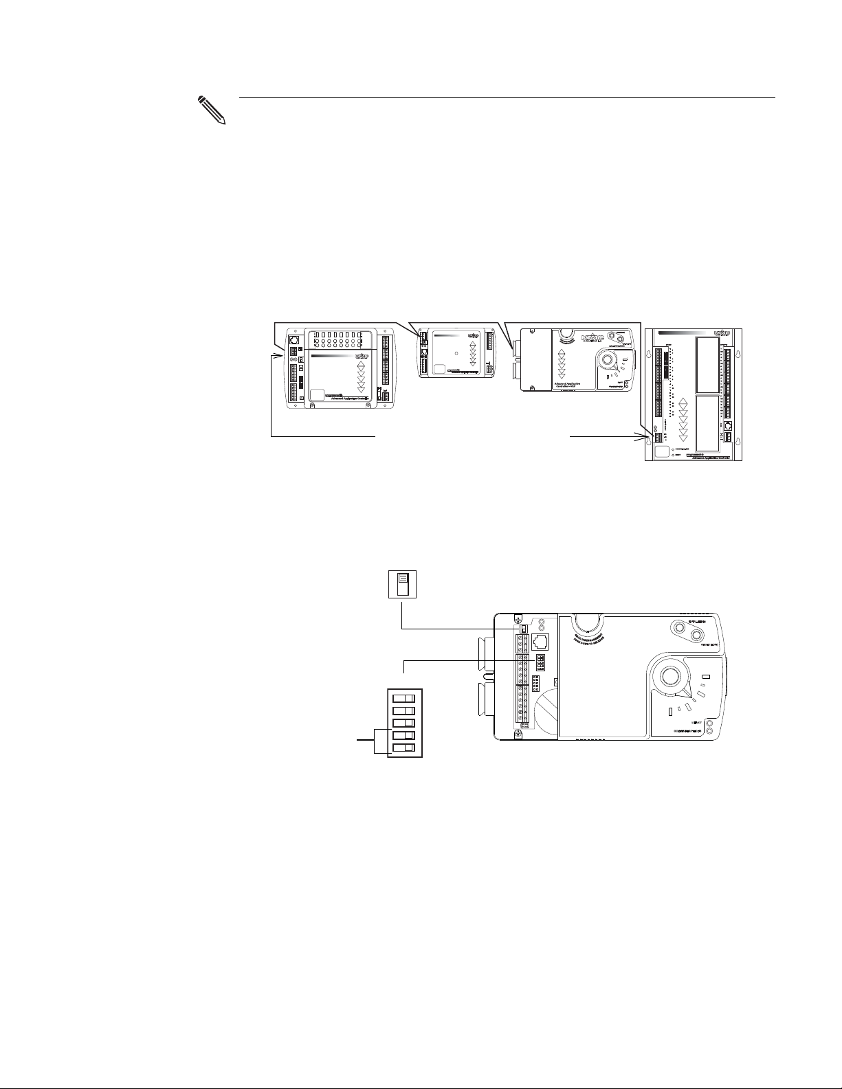
Illustration 2-3 BAC-7000 VAV series controls and indicators
Mount the controller as follows:
1. Back the set screws out of the drive hub until the shaft can fit through the collar.
2. Place the controller on the damper shaft in the approximate final position.
3. Position the anti-rotation bracket and secure it using #8 or #10 self-tapping
screws. Verify the notch in the bracket securely engages the lock tab on the
controller. (Refer to Illustration 2-3.)
4. Manually position the VAV damper in the fully open position.
5. Press the gear clutch button and rotate the drive hub in the same direction that
opened the damper. Turn the hub until it reaches a rotation limit.
6. Tighten the two set screws in the drive hub to approximately 50–inch pounds
(5.65 N
•m) to lock the hub to the shaft.
Revision C
Page 17

BAC-7000 VAV Installation, applications, and operation
MS/TP
network
Input
Output
Power
Isolation lamps
Power jumper
RJ–12
Input pull-up
resistors
MS/TP end-of-line
termination
Restart button
guide
Installing the controllers
Wiring compartment
Wiring
compartment
All input, output, power and network connection points are located beneath the
access cover. Remove the two screws that secure this cover to remove the cover.
The controller comes with a removable conduit plate. The plate provides two
inch threaded conduit couplings. If conduit connections are used, note the
0.5
following:
◆ The conduit plate may be removed by removing the two screws that secure the
access cover and removing the cover. Connect the required conduit and replace
the plate in the controller housing.
◆ The plugs may also be sliced to allow wiring to enter the controller with a
minimum of outside contaminates.
Revision C
Illustration 2-4 Connection points inside wiring compartment
17
Page 18

Installing the controllers
Note
Pull-up
resistors
Off On
Input
terminals
Connecting inputs
KMC Controls
Connecting inputs
The BAC-7000 VAV controllers have three universal inputs. Each input is configured
to support the standard application programs in the controller. By using the pull-up
resistors, either passive or active devices may be connected to the inputs.
KMC supplied Control Basic programs assigns inputs to the following functions.
◆ Connect Input 1 to the space temperature sensor input such as the 10 kΩ.
thermistor in an STE-6000 series sensor.
◆ Connect Input 2 as a setpoint input such as a 0-10 kΩ. dial on an STE-6000
series sensor.
◆ Input 3 is for a 10 kΩ. discharge air temperature sensor.
If a NetSensor is connected to the controller, the standard application
programming will use the temperature and setpoint from the NetSensor and
not from devices connected to Input 1 and Input 2.
Setting the pull–up resistors For passive input signals, such as thermistors or
switch contacts, set the pull-up switch to the On position. See
Illustration 2-5 for the
pull-up switch location.
18
Illustration 2-5 Input terminals and pull-up resistors
Ground terminals Use the GND terminal located next to the input terminals for the
input ground connection. Up to two wires, size 14–22 AWG, can be inserted into the
ground terminal. If more than two wires must be joined at a common point, use an
external terminal strip for the additional wires.
Revision C
Page 19

BAC-7000 VAV Installation, applications, and operation
Caution
Output
terminals
Output
terminals
guide
Installing the controllers
Connecting outputs
Connecting
outputs
The output terminal configuration for a BAC-7001 and BAC-7051 controllers is
different than the configuration for BAC-7003 and BAC-7053 controllers.
For a listing of the configuration of the controller output objects, see the section
Output objects on page 62.
BAC-7001 and BAC-7051 output connections
BAC-7001 and BAC-7051 controllers provide three universal outputs. These output
are rated for 0-10 volt DC loads. Returns are connected to the GND terminal next to
output O3 as shown in the illustration
BAC-7001 output terminals on page 19.
O1 O2 O3
GND
Illustration 2-6 BAC-7001 output terminals
BAC-7003 and BAC-7053 output connections
The BAC-7003 and BAC-7053 include one single-stage triac, one relay and one
universal output.
O1 T2 RTN2 R3 RTN3
Illustration 2-7 Output terminals
When connecting loads to the triac or relay output, use only the terminal
marked RTN associated with the triac or relay for the 24-volt circuit.
Output O1 This output is a universal output that can be programmed as either an
analog object for modulating reheat. The universal output is rated for 0-10 volt DC
loads. Use the GND terminal on the input connector block for the ground.
Output T2 This is a triac output programmed to switch 24-volt reheat circuits. The
output is rated for 24 volt, 1 ampere loads, and switches on zero crossing. Use the
RTN2 terminal for the T2 load.
Output R3 This is a normally open relay contact programmed to control a 24-volt
fan starting circuit. The relay contacts are rated for 24-volts at 2 amperes. Use RTN3
for the R3 load.
Output 4 Output 4 is internally connected to the actuator motor.
Revision C
19
Page 20

Installing the controllers
Note
75 feet Max.
Connecting to a NetSensor
KMC Controls
Connecting to a
NetSensor
The Network RJ-12 connector provides a connection port to a NetSensor model
KMD-1161. Link the controller to a NetSensor with a KMC Controls approved cable
up to 75 feet long. See the installation guide supplied with the NetSensor for
complete NetSensor installation instructions.
If a NetSensor is connected to the controller, the standard application
programming will use the temperature and setpoint from the NetSensor and
not from devices connected to Input 1 and Input 2.
-A S
+B
1
GND
Illustration 2-8 Connecting to a NetSensor
20
Revision C
Page 21

BAC-7000 VAV Installation, applications, and operation
S
+B
-A
S
+B
-A
S
+B
-A
guide
Installing the controllers
Connecting to an MS/TP network
Connecting to an
MS/TP network
BAC-7000 series VAV controllers BACnet MS/TP compliant controllers. For
monitoring and control by building automation system, connect them only to a
BACnet MS/TP network.
Connections and wiring
Use the following principles when connecting a controller to an MS/TP network:
◆ Connect no more than 128 addressable BACnet devices to one MS/TP network.
The devices can be any mix of controllers or routers.
◆ To prevent network traffic bottlenecks, limit the MS/TP network size to 60
controllers.
◆ Use 18 gauge, twisted pair, shielded cable with capacitance of no more than
50 picofarads per foot for all network wiring. Belden cable model #82760 meets
the cable requirements.
◆ Connect the -A terminal in parallel with all other - terminals.
◆ Connect the +B terminal in parallel with all other + terminals.
◆ Connect the shields of the cable together at each controller. For KMC BACnet
controllers use the S terminal.
◆ Connect the shield to an earth ground at one end only.
◆ Connect a KMD–5575 BACnet MS/TP repeater between every 32 MS/TP
devices or if the cable length will exceed 4000 feet (1220 meters). Use no more
than four repeaters per MS/TP network.
◆ Place a KMD–5567 surge surpressor in the cable where it exits from a building.
See Application Note AN0404A, Planning BACnet Networks for additional
information about installing controllers.
Illustration 2-9 MS/TP network wiring
Revision C
21
Page 22
Installing the controllers
Note
Set end-of-line termination to
On in these controllers only.
EOL switch
Network
disconnect
switch
Off On
Connected
Disconnected
Connecting to an MS/TP network
The BAC-7000 terminals are labeled -A, +B and S. The S terminal is provided
as a connecting point for the shield. The terminal is not connected to the
ground of the controller. When connecting to controllers from other
manufacturers, verify the shield connection is not connected to ground.
End of line termination switches
The controllers on the physical ends of the EIA-485 wiring segment must have endof-line termination installed for proper network operation. Set the end-of-line
termination to On using the EOL switches.
KMC Controls
Illustration 2-10 Location for end-of-line termination
Illustration 2-5 shows the position of the controllers End-of-Line switches
associated with the MS/TP connection points.
Illustration 2-11 Location of EOL switch
22
Revision C
Page 23
BAC-7000 VAV Installation, applications, and operation
Note
Total (High)
Static (Low)
Power
terminals
Power
jumper
guide
Installing the controllers
Connecting an airflow sensor
Connecting an
airflow sensor
Connecting power
An airflow sensor is incorporated as one of the inputs to the controller. Remove the
plugs and connect the tubing from the pitot assembly to the airflow sensor inputs
above the drive hub. (See
Illustration 2-12.). The airflow sensor is programmed as
input 4.
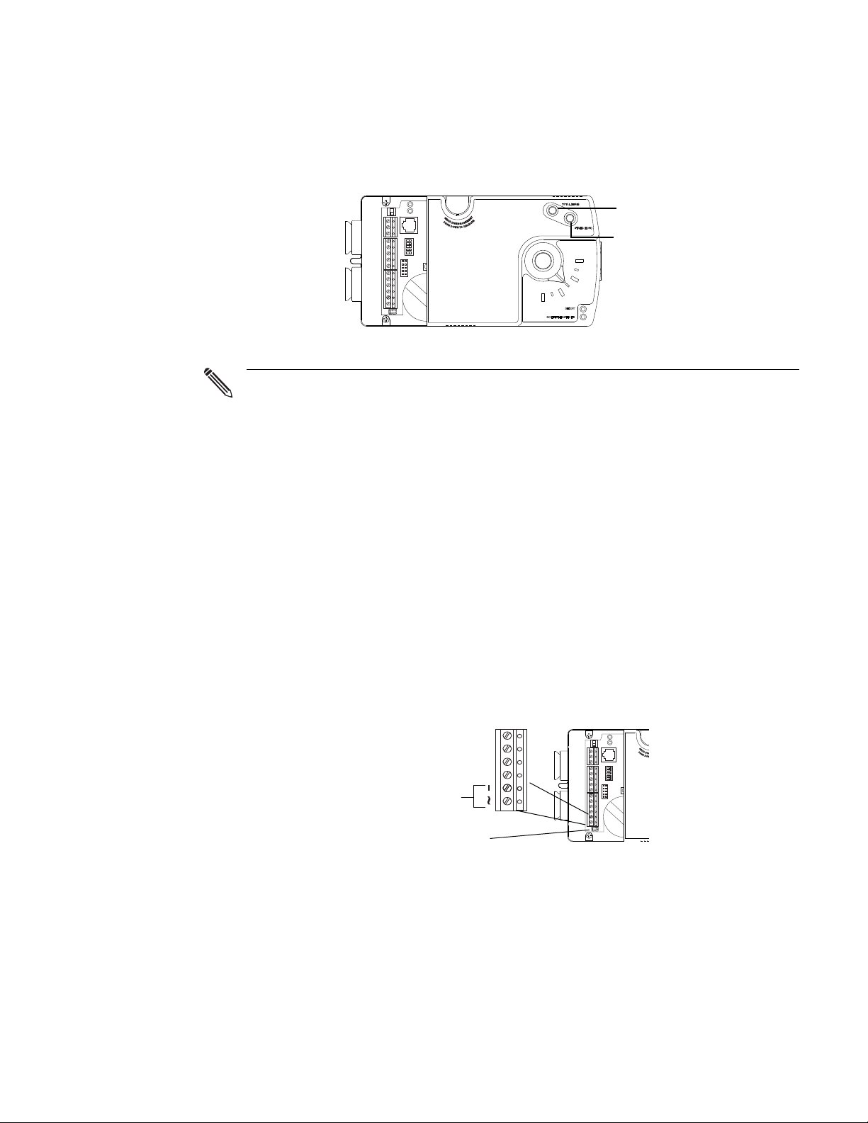
Illustration 2-12 Airflow sensor inputs
Mount the controller close enough to the pitot tubes to keep the tubing length
to be less than 24 inches between the controller’s inputs and the tubes.
The controllers require an external, 24 volt, AC power source. Use the following
guidelines
when choosing and wiring transformers.
◆ Use a KMC Controls Class–2 transformer of the appropriate size to supply
power to the controllers.
◆ KMC Controls recommends powering only one controller from each
transformer.
◆ Do not run 24 volt, AC power from within an enclosure to external controllers.
Connect the 24 volt AC power supply to the power terminal block on the lower right
side of the controller near the power jumper. Connect the ground side of the
transformer to the – terminal and the AC phase to the ~
(phase) terminal. Power is
applied to the controller when the transformer powered and the power jumper is in
place.
Illustration 2-13 Power terminals and jumper
Revision C
23
Page 24

Installing the controllers
Connecting power
KMC Controls
24
Revision C
Page 25
BAC-7000 VAV Installation, applications, and operation guide
Network
disconnect
switch
Connected
Disconnected
Ready LED
Communication LED
Gear clutch button
Damper
position
indicator
Network
isolation
bulbs
Restart button
Power jumper
SECTION 3
Operation
This section provides a brief overview of the BAC-7000 series VAV
controllers. Review this material before installing the controllers.
Operation
Controls and Indicators
Once configured, programmed and powered, the controller requires very little user
intervention.
The following topics describe the controls and indicators found on the controller.
Additional information for automatic addressing functions are described in the
guide MS/TP Automatic MAC Addressing Installation Instructions that is available
from the KMC Controls web site.
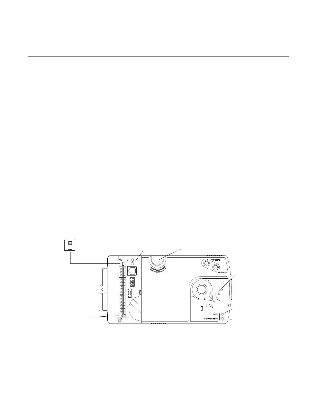
Network disconnect switch
The network disconnect switch is located near the RJ-12 connector. Use this switch to
enable or disable the MS/TP network connection. When the switch is ON the
controller can communicate on the network; when it is OFF, the controller is isolated
from the network.
Alternately, you may remove the isolation bulbs to isolate the controller from the
network.
Ready LED
The green Ready LED indicates the state of the controller. This includes automatic
addressing functions that are fully described in the guide MS/TP Addressing For
BACnet Controllers.
Revision C 25
Illustration 3-1 Controls and indicators
Page 26

Operation
Controls and Indicators
KMC Controls
Power up During controller initialization, the Ready LED is continuously
illuminated for 5 to 20 seconds. Once initialization is complete, the Ready LED
begins flashing to indicate normal operation.
Normal operation During normal operation, the Ready LED flashes a repeating
pattern of one second on and then one second off.
Restart button acknowledge The restart button includes several functions for
automatic addressing that are acknowledged with the Ready LED. When the restart
button is pressed, the Ready LED illuminates continuously until either of the
following take place:
• The restart button is released.
• The restart button time-out period is reached and a restart operation is
complete. Restart button operations are listed in the following table.
Table 3-1 Ready LED patterns for restart button operations
Controller state LED pattern
The controller is set as an automatic
addressing anchor. The MAC in the
controller is set to 3
The controller has sent the automatic
addressing lock command to the network
No restart operation Ready LED remains unlit until the restart
A rapid repeating pattern of a short flash
followed by a short pause.
Two short flashes followed by a long
pause. The pattern repeats until the restart
button is released.
button is released.
Communications (Com) LED
The yellow Communications LED indicates how the controller is communicating
with other controllers on the network.
Sole master Repeating pattern of a long flash and a short pause that repeats once a
second. It indicates that the controller has either generated the token or is a sole MS/
TP master and has yet to establish communications with other MS/TP devices.
Token passing A short flash each time the token is passed. The frequency of the
flash is an indication of how often the device receives the token.
Nomad patterns There are three Com LED patterns that indicate that the controller
is an automatic addressing nomad controller that is receiving valid MS/TP traffic.
Table 3-2 Automatic addressing nomad patterns
26
Controller state LED pattern
Lost nomad A long flash
Wandering nomad A long flash followed by three short
flashes
Assigned nomad Three short flashes followed by a long
pause.
Revision C
Page 27

BAC-7000 VAV Installation, applications, and operation
guide
Error conditions for the LEDs
Error conditions are indicated with a combination of the Ready and Com LEDs.
◆ If the Ready LED and Com LED are both unlit, check the fuse, power, and
connections to the controller.
◆ If the Ready LED alternates with the Com LED at a one-half-second rate, there
is an error in the controller’s memory. Restoring the controller to factory
default settings will typically resolve the problem.
Isolation bulbs
The two network isolation bulbs, located next to the network switch, serve three
functions:
◆ Removing the bulbs opens the EIA-485 circuit and isolates the controller from
the network.
◆ If one or both bulbs are lit, it indicates the network is improperly phased. This
means that the ground potential of the controller is not the same as other
controllers on the network.
◆ If the voltage or current on the network exceeds safe levels, the bulbs operate as
fuses and may protect the controller from damage.
Operation
Controls and Indicators
Gear clutch button
To manually position the damper, press the gear clutch button and rotate the drive
hub.
Revision C
27
Page 28

Operation
Caution
Note
Caution
Restoring factory settings
KMC Controls
Restoring factory
settings
If the controller appears to be operating incorrectly, or is not responding to
commands, you may need to reset the controller. Remove the cover and locate the
red restart button.
To perform a reset or restart, locate the red restart push-button and then—in
order—use one of the following procedures.
1. A warm start is the option least disruptive to the network and should be tried
first.
2. If problems persist, then try a cold start.
3. If the problems continues, restoring the controller to factory settings may be
required.
Read all of the information in this section before proceeding!
Momentarily pushing the red reset button while the controller remains
powered will have no effect on the controller.
Performing a warm start
A warm start changes the controller as follows:
◆ Restarts the controller’s Control Basic programs.
◆ Leaves object values, configuration, and programming intact.
In the unlikely event that the checksum test in RAM fails during the warm
start, the controller will automatically perform a cold start. During a cold start,
controller outputs may abruptly turn connected equipment on and off. To
prevent equipment damage, turn connected equipment off or temporarily
remove the output terminal blocks from the controller before performing a
warm start.
Do either of the following to perform a warm start:
◆ Reinitialize the controller with either BACstage or TotalControl Design Studio.
◆ Remove the power jumper for a few seconds and then replace it.
Performing a cold start
Performing a cold start changes the controller as follows:
◆ Restarts the controller programs.
◆ Returns all object states to their initial factory settings until the controller
programs update them.
◆ Leaves configuration and programming intact.
28
Revision C
Page 29

BAC-7000 VAV Installation, applications, and operation
Caution
Note
Caution
guide
Returning object values to their relinquished defaults during a cold start may
abruptly turn connected equipment on or off. To prevent equipment damage,
turn connected equipment off or temporarily remove the output terminal
blocks from the controller before performing a warm start.
To perform a cold start:
1. While the controller is powered, press and hold the restart button.
2. Remove the power jumper.
3. Release the red button before replacing the power jumper.
A cold start performed by this method is the same as performing a cold start
with BACstage or from TotalControl Design Studio.
Restoring to factory settings
Restoring a controller to factory settings changes the controller as follows:
Operation
Restoring factory settings
◆ Removes all programming.
◆ Removes all configuration settings.
◆ Restores the controller to factory default settings.
Resetting the controller erases all configuration and programming. After
resetting to factory settings, you must configure and program the controller to
establish normal communications and operation.
To reset the controller to factory settings.
1. If possible, use BACstage or TotalControl Design Studio to backup the
controller.
2. Remove the power jumper.
3. Press and hold the red restart button.
4. Replace the power jumper while continuing to hold the restart button.
5. Restore configuration and programming with BACstage or TotalControl
Design Studio.
Revision C
29
Page 30

Operation
Maintenance
KMC Controls
Maintenance
BAC-7000 series VAV controllers require no routine maintenance. If necessary, clean
with a damp cloth and mild soap.
30
Revision C
Page 31

BAC-7000 VAV Installation, applications, and operation guide
SECTION 4
Configuration and set up
The topics in this section are advanced topics for control technicians
and engineers. Carefully review this information before installing or
operating a controller.
Configuration of a BAC-7000 series VAV controller sets all of the values and settings
required to control a VAV terminal unit. Typically, these settings do not change after
the installation and commissioning process.
To set up the configuration functions, you will need the following items and
information.
Assigning network addresses
◆ Details about the VAV terminal unit including the configuration for fans and
reheat.
◆ A BACnet operator workstation such as BACstage or TotalControl.
◆ The building automation system plans for controllers connected to a network.
Every controller on a BACnet MS/TP network must have a unique device instance
and MAC address. Assigning the MAC address and device instance to a controller
can be done by using either the automatic or manual method.
Automatic addressing
If the controller is part of a KMC Controls network that uses automatic addressing,
follow the directions in the guide MS/TP Automatic MAC Addressing Installation
Instructions that is available from the KMC Controls web site.
Manual addressing
To manually address a new controller it must first be changed to an anchor
controller by doing the following:
1. Set the network switch to Off (disconnected).
2. Press and hold the restart button for 10 seconds. The Ready LED will start
flashing rapidly. The Com LED will remain dark.
3. Release the restart button.
4. Turn off controller power.
5. Set the anchor network switch to On (connected).
6. Turn on controller power. The Ready LED will blink slowly and the Com LED
will flash rapidly. This controller is now an anchor with a MAC address of 3.
Revision C 31
Page 32

Configuration and set up
Note
Configuring for pressure independent VAV
Once a controller is converted to an anchor controller, connect it to a BACnet
operator workstation and set the following properties.
◆ MAC address
◆ Device instance number
◆ Baud rate
KMC Controls
Configuring for
pressure
independent VAV
The BAC-7000 VAV controllers are supplied with programming and object
configuration for single-duct VAV cooling. The following value objects must be set
or verified with a BACnet operator workstation such as BACstage or TotalControl
for correct operation.
When changing any of the value objects in this procedure, make the changes to
the Relinquish Default property. If the change is added to the Priority Array
property at any other level, the change will be deleted when the controller
restarts.
Configure the damper direction to close
The CW_CLOSE value object sets the direction the controller will rotate the damper
to the closed position.
◆ Set this property to Yes (Active or 1) to set the controller to close the damper in
the clockwise direction.
◆ Set the property to No (Inactive or 0) to set the controller to close the damper in
the counter clockwise direction.
Change this value in the Relinquish Default property of Binary Value object 4.
Enter the volume correction factor
The volume correction factor is used to calculate airflow based on the primary air
inlet size of the VAV terminal unit. For round ducts, choose the correction factor
from the following table. Enter the factor in the Relinquish Default property of
Analog Value object 22, VOLFACTR.
32
Table 4-1 Volume factor for round ducts (inches)
Diameter Circumference Volume factor
4 12 5/8 0.087
5 15 3/4 0.136
6 18 7/8 0.196
7 22 0.267
8 25 1/8 0.349
9 28 1/4 0.442
10 31 3/8 0.545
12 37 3/8 0.785
14 44 1.068
16 50 1/4 1.396
Revision C
Page 33

BAC-7000 VAV Installation, applications, and operation
Volume factor =
0.785 x Diameter
144
2
guide
For other sizes of round ducts, use the following formula. Diameter is in inches.
For rectangular ducts, use the following formula. Width and Height are in inches.
Configuration and set up
Configuring for pressure dependent VAV
Volume factor =
Width x Height
144
Enable or disable reheat
The BAC-7000 VAV controllers are supplied with reheat enabled. To disable reheat,
set the Relinquish Default property of REHEAT, Binary Value object 5, to
Inactive
(0).
Configure auxiliary airflow (optional)
Auxiliary airflow sets the airflow when reheat is active and is not used if reheat is
disabled. Enter the value for the auxiliary airflow in the Relinquish Default property
of Analog Value object 28, AUX_FLOW.
Set the airflow limits
VAV airflow limits can be set with either a KMD-1161 NetSensor or with a BACnet
operator workstation. Enter the values in the Relinquish Default properties of
Analog Value objects 20 and 21, MIN_FLOW, and MAX_FLOW.
To set the values with a NetSensor, follow the procedures in the section Balancing
with a NetSensor on page 35.
Set the temperature setpoint limits
The temperature setpoint limits place limits on the highest heating setpoint and the
lowest cooling setpoint a user can enter. Enter the values in the Relinquish Default
properties of Analog Value objects 11 and 12, STPT_MIN and STPT_MAX.
Configuring for
pressure
dependent VAV
Revision C
To operate a BAC-7000 series VAV controller as a pressure dependent controller, use
a BACnet operator workstation to make the following changes.
◆ Halt Program object 1 and enable Program object 2 to run. If available, set the
program object to automatically run on a coldstart.
◆ Configure the damper direction to close on page 32
◆ Enable or disable reheat on page 33
◆ Set the temperature setpoint limits on page 33
33
Page 34

Configuration and set up
Configuring for pressure dependent VAV
KMC Controls
34
Revision C
Page 35

BAC-7000 VAV Installation, applications, and operation guide
Note
SECTION 5
Balancing with a NetSensor
Topics in this section are for control technicians or engineers who
will be balancing the airflow in the controllers.
The airflow balancing procedure described in this section requires the following
items.
◆ An airflow hood or other accurate method to measure airflow.
◆ An KMD-1161 NetSensor. If the system does not include one of these sensors,
temporarily disconnect the installed sensor and connect a KMD-1161 as a
service tool.
◆ The engineering design specifications for the minimum and maximum airflow
setpoints.
Balancing overview
The procedures in this section are for pressure independent systems only.
The airflow setpoints can be entered either in the balancing routines or they can be
entered through the use of a BACnet operator workstation. This is described in the
section
entered, they must be entered before balancing.
Balancing airflow is the process of calibrating the internal airflow sensor to a known
standard. In the field, airflow is measured with an airflow hood or other measuring
instrument and then compared to the airflow measurements from the sensor in the
controller. The balancing process uses a KMD-1161 NetSensor as the technicians
service tool for initiating the balancing sequence and entering actual flow
measurements.
When the balancing sequence starts, all other functions of the controller are locked
out.
Configuration and set up on page 31. Regardless of how these setpoints are
Revision C 35
Page 36
Balancing with a NetSensor
SET
POINT
TEMP O.A.T. OVERRIDE
B5 B6 B7
2
1
5
6
Choose airflow
1-Max 0-Min
Space temperature
Minimum airflow
setpoint
Actual airflow at
maximum
3
4
7
Airflow (CFM)
Actual airflow at
minimum
Maximum airflow
setpoint
The balancing procedure
KMC Controls
The balancing
procedure
This balancing procedure requires a KMD-1161 NetSensor as a service tool. If other
sensors are permanently installed, temporarily connect a KMD-1161 to the
controller, perform airflow balancing, and then return the original sensors to the
installation.
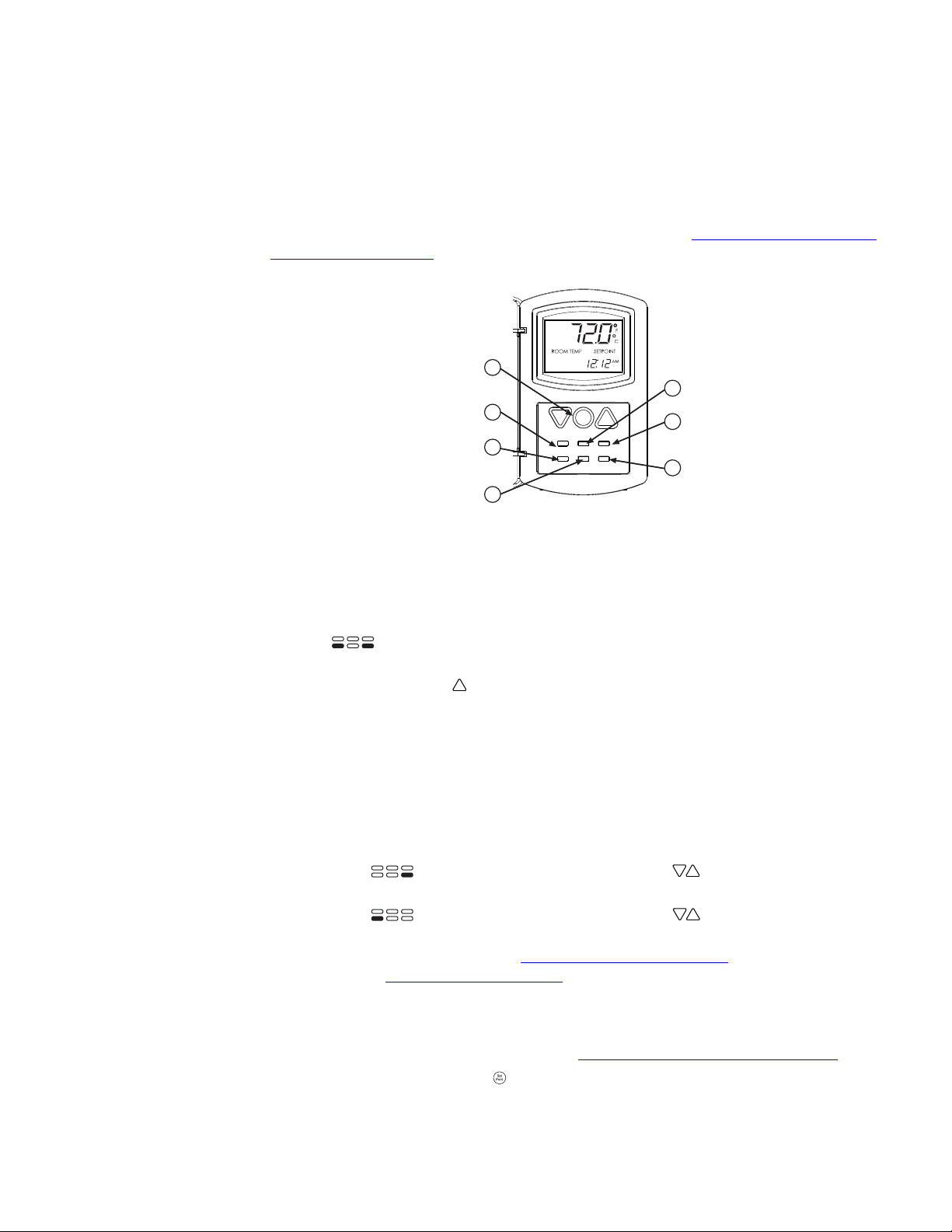
In the following procedures, the NetSensor buttons are referenced as they are
labeled on a standard KMD-1161. If the NetSensor has custom labeling, refer to the
button diagram included with each step or the illustration
Standard NetSensor button
assignments on page 36.
Illustration 5-1 Standard NetSensor button assignments
Start the balancing routine To start balancing or to set the airflow setpoints, do the
following.
1. Start the balancing routine by pushing together and then releasing B5 and
B7
. The display changes to AUX and then to OFF when the buttons are
released.
2. Push the Up button . The display changes to ON. The controller is now in the
balancing mode.
3. Wait approximately 15 seconds.
4. Continue with the procedure Enter airflow setpoints or Balance the airflow.
Enter airflow setpoints If required, enter the airflow setpoints from the NetSensor.
This is not necessary if these setpoints are entered from a BACnet operator
workstation during controller configuration.
1. Start balancing as described in the previous procedure.
2. Push B7 and use the Up and Down buttons to enter the maximum
airflow setpoint.
3. Push B5 and use the Up and Down buttons to enter the minimum
airflow setpoint.
4. Continue with the procedure Balance the airflow on page 36 or follow the
procedure End balancing on page 37.
Balance the airflow The following procedure balances airflow at the minimum and
maximum airflow setpoints.
36
1. If not in balancing, see the procedure Start the balancing routine on page 36.
2. Press the Setpoint button . The NetSensor should display “01”. This is the
indication that the controller is rotating the damper to the maximum airflow
setpoint.
Revision C
Page 37
BAC-7000 VAV Installation, applications, and operation
guide
• If the NetSensor is still displaying the temperature setpoint, wait
approximately 15 seconds.
• If the value is “00” press the Up button to change the display to”01”.
3. Monitor the actual airflow by pushing O.A.T. .
4. Once the actual airflow stabilizes, measure the airflow at the VAV outlet and
note the measurement.
5. Push B6 and use the Up and Down buttons to enter the measured
maximum airflow.
6. Press the Setpoint button and press the Down button. The display changes
to “00”. This is the indication that the controller is driving the damper to the
minimum airflow setpoint.
7. Monitor the actual airflow by pushing O.A.T .
8. Once the actual airflow stabilizes, measure the airflow at the VAV outlet and
note the measurement.
9. Push OVERRIDE and use the Up and Down buttons to enter the
measured minimum airflow.
End balancing End balancing by performing the following procedure. Balancing
will automatically end after two hours from the time the last button is pushed.
Balancing with a NetSensor
The balancing procedure
1. End balancing by pushing together and then releasing B5 and B7 . The
display changes to AUX and then to ON when the buttons are released.
2. Push the Down button . The display changes to OFF. The controller is now in
the normal operating mode.
Revision C
37
Page 38

Balancing with a NetSensor
The balancing procedure
KMC Controls
38
Revision C
Page 39

BAC-7000 VAV Installation, applications, and operation
guide
SECTION 6
Sequences of operation
Topics in the section cover the sequences of operation for the
BAC-7000 series VAV controllers. These are advanced topics for
control technicians and engineers.
These sequences of operation are descriptions of each major components of the
BAC-7000 VAV programming. They are provided as an aid to understanding on how
the controllers operate.
This section covers the following sequences of operation.
◆ Input sources on page 39
◆ Space setpoints on page 40
◆ Occupancy and standby on page 40
◆ PID control loops on page 41
◆ Changeover on page 41
◆ Pressure independent airflow sequence on page 41
◆ Pressure dependent temperature control on page 41
◆ Damper operation on page 42
◆ Fan operation on page 42
◆ Reheat sequence on page 42
◆ Balancing sequence on page 43
Sequences of operation
Input sources
Input sources
Revision C
The BAC-7000 series VAV controllers require specific sensors for room temperature,
room setpoint, and airflow through the VAV terminal unit.
The controllers are set up for KMD-1161 NetSensors. When a NetSensor is connected
to a controller, the programming automatically detects the sensor and updates
Analog Value objects AV1, SPACESTP, and AV2, SPACESSTPT, from the values
passed from the NetSensor.
If a NetSensor is not detected, the values from Analog Inputs objects AI1 and AI2,
ROOMTEMP and STESETPOINT, are passed to Analog Value objects AV1 and AV2.
Input AI1 is configured for a Type-II, 10 kΩ. thermistor and input AI2 is configured
for a 10 kΩ. potentiometer.
A third input is configured as Analog Input object AI3 for a Type-III, 10 kΩ.,
discharge air temperature sensor. This input is not required for any of the
programming sequences but may be installed for monitoring by a BACnet operator
workstation or another controller on the building management system network.
The airflow sensor is an internal, flow-through sensor that is connected to airflow
pickup tubes on the VAV terminal unit inlet. The input is represented by Analog
Input object AI4 and is configured to represent airflow in feet-per-minute.
39
Page 40

Sequences of operation
Space setpoints
KMC Controls
Space setpoints
The BAC-7000 VAV controllers use the following setpoints based on the user-entered
setpoint or the state of occupancy and standby. See the topic
on page 40 for a description of these modes.
Active setpoint—The active setpoint is the current setpoint the controller uses to
maintain temperature in the space. It is the Controlled Input property for Loop 1.
Controller programming sets this value to either the Cooling Setpoint or Heating
setpoint based on the state of Heating/Cooling value object. The active setpoint is
stored in Analog Value object AV26,
ACTIVESP.
Occupancy and standby
Table 6-1 Active setpoint calculations
Cooling setpoint Heating setpoint
Occupied Space setpoint + 1/2 deadband Space setpoint – 1/2 deadband
Standby Space setpoint + offset Space setpoint – offset
Unoccupied Unoccupied cooling setpoint Unoccupied heating setpoint
Space setpoint—This is the setpoint entered or selected by the user and is stored in
Analog Value object AV2, SPACESSTPT. The value is either the value set from the
NetSensor or Analog Input object
calculated from this setpoint. See the topic
Setpoint limits—The setpoint limits are entered by the controls technician during
controller setup and system commissioning. Analog Value object
limits the lowest cooling setpoint and Analog Value object
the highest heating setpoint allowed regardless of the setting or entry of the user
space setpoint.
AI1. The Active and Standby setpoints are
Input sources on page 39.
AV11, STPT_MIN,
AV12, STPT_MAX, limits
Occupancy and
standby
Unoccupied setpoints—These setpoints are entered by the controls technician
during controller setup and system commissioning. Analog Value objects AV39 and
AV40, UNOCC_HTG_SP and UNOCC_CLG_SP, are the setpoints used when the
system is unoccupied.
Standby setpoint—Standby setpoints are used when the controller is in the standby
state. It is a value calculated from the current active setpoint and the value of Analog
Value object AV3, OFFSET. The standby offset value is entered by the controls
technician during controller setup and system commissioning. See the topic
Occupancy and standby on page 40.
The BAC-7000 VAV controllers have no internal programming to enable a change to
the occupancy or standby modes.
Occupancy—Binary Value object BV2, UNOCC, sets the state controller occupancy.
When the controller is in the occupied state, the active setpoint is calculated as
described in the topic
unoccupied state, either the cooling or heating unoccupied setpoint is used as the
active setpoint. The state of this object can be controlled by a schedule object, custom
Control Basic programming, or from another device on the building management
network.
Standby—The Binary Value object BV1, STANDBY, sets the state of standby or
occupied. When the controller is in the occupied standby state, the standby setpoint
is used as the active setpoint. The state of this object can be controlled by a schedule
object, custom Control Basic programming, or from another device on the building
management network.
Space setpoints on page 40. When the controller is in the
40
Revision C
Page 41

BAC-7000 VAV Installation, applications, and operation
guide
Sequences of operation
PID control loops
PID control loops
A PID control loop calculates an error value from the difference between a measured
input value and a setpoint value. The error value is expressed as a percentage and is
typically used in a BAS controller to control the state of an output. When the
difference between the setpoint and measured input is large, the error is large. As
the system reduces the difference between the setpoint and measured input, the
error becomes smaller.
The BAC-7000 series VAV controllers use three PID loops.
◆ The active setpoint loop, Loop object 1—This is a direct-acting loop. It
compares the room temperature to the active setpoint to determine the VAV
flow requirement. The output of the loop is a percentage passed to Analog
Value object AV16, LP1.
◆ The flow request loop, Loop object 2—This is a direct-acting loop. It compares
actual airflow in Analog Value object AV27, VOLUME1 to the requested flow in
Analog Value object AV25, RQSTFLOW. The output of the loop is passed to
Analog Value object AV17, LP2, and is used to calculate the movement of the
damper to control airflow.
◆ The heating loop, Loop object 3—This reverse acting loop compares room
temperature to Analog Value object AV29, HEAT_SP. The output of the loop is
passed to Analog Value object AV18, LP3, to calculate the call for reheat. See the
Reheat sequence on page 42 for a description of the reheat sequence.
topic
The PID loops in the controllers are standard BACnet objects and are listed in the
Loop objects on page 63.
topic
Pressure independent airflow sequence
Pressure dependent temperature control
Changeover
For pressure independent VAV installations, the airflow through the VAV terminal
unit is determined by Loop 1 and Loop 2 both of which are direct acting loops.
Loop object 1, a direct acting loop, compares the room temperature to the active
setpoint to determine a required change in temperature which is passed to Analog
Value object AV16, LP1. The value of LP1 is inverted if in heating mode and not
inverted for cooling and then passed to Analog Value object 25, RQSTFLOW, as the
setpoint reference property for Loop object 2. This is compared to the actual airflow.
The result is passed to Analog Value object AV17, LP2. LP2 is then used by the
damper routine to open or close the damper.
See also the topic, Damper operation on page 42.
For pressure dependent (bypass) control, only Loop object 1 is used to control
damper position.
Loop object 1, a direct acting loop, compares the room temperature to the active
setpoint to determine a required change in temperature. The temperature change is
stored in Analog Value object AV16, LP1. LP1 is then used by the damper routine to
open or close the damper.
The BAC-7000 VAV controllers are configured as cooling only controllers. The
controller can be commanded to heating from another controller connected to the
building management system network or by adding custom Control Basic
programming. Changeover from cooling to heating is controlled by the Binary Value
object BV3, HEATING.
Revision C
41
Page 42

Sequences of operation
Damper operation
KMC Controls
Damper operation
Fan operation
Reheat sequence
The damper position is calculated and then commanded to move through Analog
Output object AO4, MOTOR. When the output is commanded to 0 volts the motor
drives the damper counterclockwise, 10 volts drives the damper clockwise, and 5
volts stops the damper. Controller programming limits the motor run-time in either
direction to no longer than 6 minutes. See
page 41 or Pressure dependent temperature control on page 41 for a description of how
damper position is determined.
Damper position is indicated by Analog Value object 32, DMPR_POS. It is calculated
with programming by measuring the time the damper has been commanded open
or closed and comparing it to the time required for 90° rotation. It is not used as
feedback in the control sequence.
(Pressure Independent only) If the controller is configured for fan operation, the
controller will start the fan when there is a call for reheat. The fan starts when the
Reheat Setpoint loop is above 5% and stops 30 seconds after the reheat output is
turned off. See the topic
BAC-7000 VAV controllers simultaneously control modulating and On/Off reheat
outputs. All reheat is controlled by Loop object 3 which is described in the topic
control loops on page 41.
Binary Value object BV5, REHEAT, enables both modulating and On/Off reheat.
Reheat sequence on page 42.
Pressure independent airflow sequence on
PID
Modulating reheat The controller controls for modulating reheat with 0-10 volts
DC at Analog Output object AO1, ANALOG_HEAT. On a call for reheat, the reheat
output is modulated over the span of the Heating Setpoint loop. If the loop is less
than 5%, the reheat output remains at zero.
HTG %
100
Reheat loop%
5
0
Illustration 6-1 Modulating reheat operation
HTG SPAN
HTG SP
Room temp increase
42
Revision C
Page 43

BAC-7000 VAV Installation, applications, and operation
Off
On
Reheat
100%
50%
5%
HTG SP
HTG SPAN Room temp. increase
Heat loop increase
0%
guide
On/Off reheat When reheat is enabled, the controller turns on the Binary Output 2
when the output of Loop object 3 reaches 50%. The output will remain on until the
output of the loop falls below 5%.
Staged reheat options The BAC-7000 controllers do not directly support staged
reheat. Staged reheat can be added by connecting an external staging relay to the
modulating reheat analog output. See the section Applications for BAC-7000 series
VAV controllers on page 45 for adding the staging relay.
Sequences of operation
Balancing sequence
Illustration 6-2
Balancing
sequence
Balancing airflow is the process of calibrating the internal airflow sensor to a known
standard. In the field, airflow is measured with an airflow hood or other measuring
instrument and then compared to the airflow measurements from the sensor in the
controller. The balancing process uses a KMD-1161 NetSensor as the technicians
service tool for initiating the balancing sequence and entering actual flow
measurements.
When the balancing sequence starts, all other functions of the controller are locked
out.
At the start of the sequence, the technician uses the NetSensor to drive the damper
open until the airflow reaches the maximum airflow setpoint. An airflow
measurement is made with an airflow hood and the actual airflow value is entered
into the controller. Once the actual airflow is entered, the technician commands the
controller to drive the damper closed to the minimum airflow setpoint. Another
measurement is made with the flow hood and that measurement is entered into the
controller.
After both measurements are entered, the programming in the controller calculates
airflow correction factors which are used to adjust measurements from the internal
airflow sensor. Balancing is complete and the controller is returned to normal
operation.
Balancing automatically ends two hours after the last button is pushed.
For the procedure to use the balancing routine, see the section Balancing with a
NetSensor on page 35.
Revision C
43
Page 44

Sequences of operation
Balancing sequence
KMC Controls
44
Revision C
Page 45

BAC-7000 VAV Installation, applications, and operation guide
SECTION 7
Applications for BAC-7000 series VAV controllers
This section covers the drawings, materials, and instructions for
specific VAV applications.
Each BAC-7000 VAV model is designed for a specific set of applications. The
following topics are for control technicians and engineers that will design
installations and install the controllers
The application drawings in this section are supported by the programming
supplied in the BAC-7000 series VAV controllers. Both pressure independent and
pressure dependent (bypass) applications are supported.
◆ Pressure independent applications on page 46
◆ Pressure dependent applications on page 54
Revision C 45
Page 46

Applications for BAC-7000 series VAV controllers
Pressure independent applications
KMC Controls
Pressure
independent
applications
The following pressure independent applications and configurations are supported
by BAC-7000 series VAV controllers.
◆ BAC-7001 or BAC-7051 with reheat and parallel fan on page 46
◆ BAC-7001 or BAC-7051 with staged reheat and parallel fan on page 48
◆ BAC-7003 or BAC-7053 with reheat and parallel fan on page 50
◆ BAC-7003 or BAC-7053 staged reheat and parallel fan on page 52
For pressure dependent applications, see the topic Pressure dependent applications on
page 54.
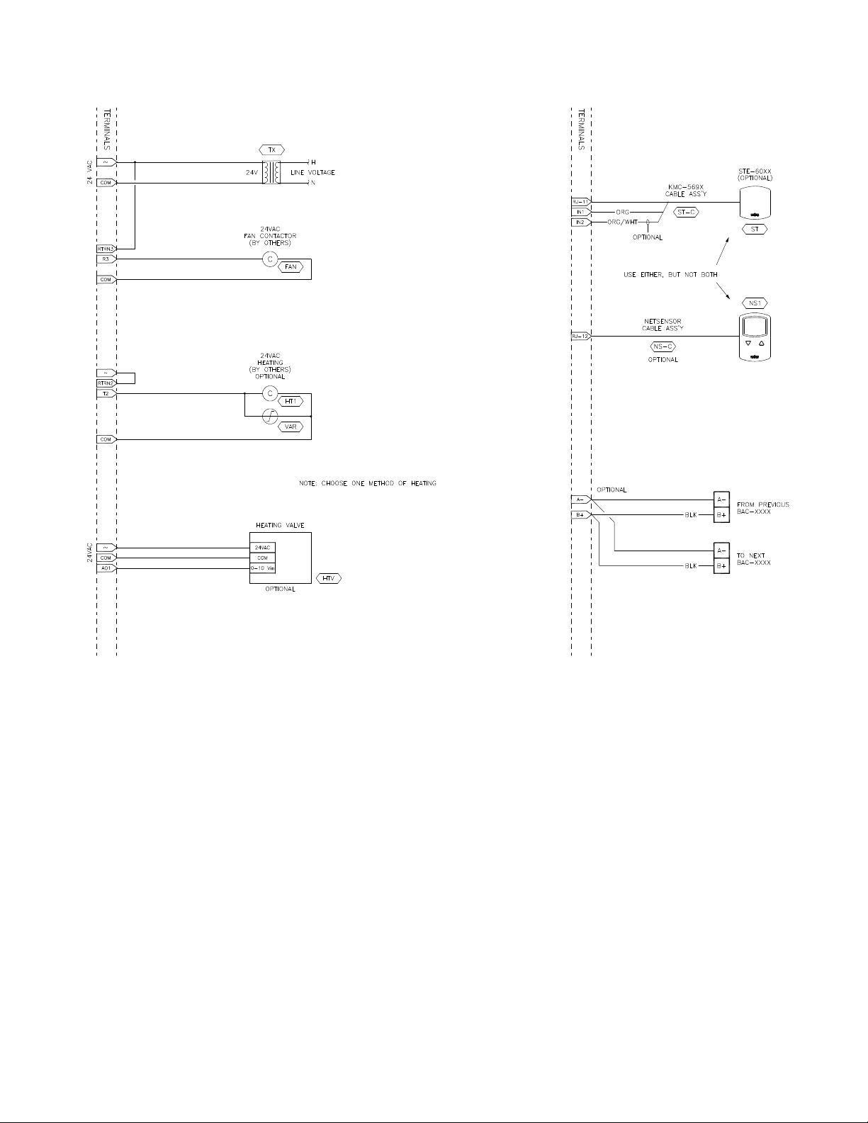
BAC-7001 or BAC-7051 with reheat and parallel fan
The standard programming in a BAC-7001 or BAC-7051 controller supports parallel
fan operation and On/Off reheat or modulating reheat. External relays are required
to switch the fan and On/Off reheat AC circuits.
◆ The fan output switches a relay for 24 volt AC pilot duty.
◆ The modulating option for reheat can control either an electric reheat unit with
an analog input or a modulating hot water valve. The analog reheat output at
output terminal AO1 varies between 0 and 10 volts DC.
◆ The On/Off reheat output switches a relay for 24 volt AC pilot duty.
For installation details, see the diagram Pressure independent BAC-7001 or BAC-7051
with reheat and parallel fan on page 47.
To configure the controller, see the topic Configuring for pressure independent VAV on
page 32.
Table 7-1 Bill of material for BAC-70x1 with reheat and parallel fan
REFERENCE PART # PART DESCRIPTION
DDC BAC-70X1 BACNET AAC FOR VAV, 3UI
AF SSS-100X AIRFLOW SENSOR, CHOOSE SIZE 'X' FROM DATA
SHEET
ST STE-60XX-10 CHOOSE 6011 OR 6014 SPACE TEMP SENSOR MODEL
ST-C KMD-569X TEMP SENSOR PLENUM CABLE W/CONN.
CHOOSE LENGTH
NS1 KMD-1161 NETSENSOR
FAN REE-3112 12VDC Control Relay
HT1 REE-3112 12VDC Control Relay
TX XEE-6311-50 Control Transformer, 120/240/277/480VAC-24VAC,
50VA
46
Revision C
Page 47

BAC-7000 VAV Installation, applications, and operation
guide
Applications for BAC-7000 series VAV controllers
Pressure independent applications
Illustration 7-1 Pressure independent BAC-7001 or BAC-7051 with reheat and parallel fan
Revision C
47
Page 48

Applications for BAC-7000 series VAV controllers
Pressure independent applications
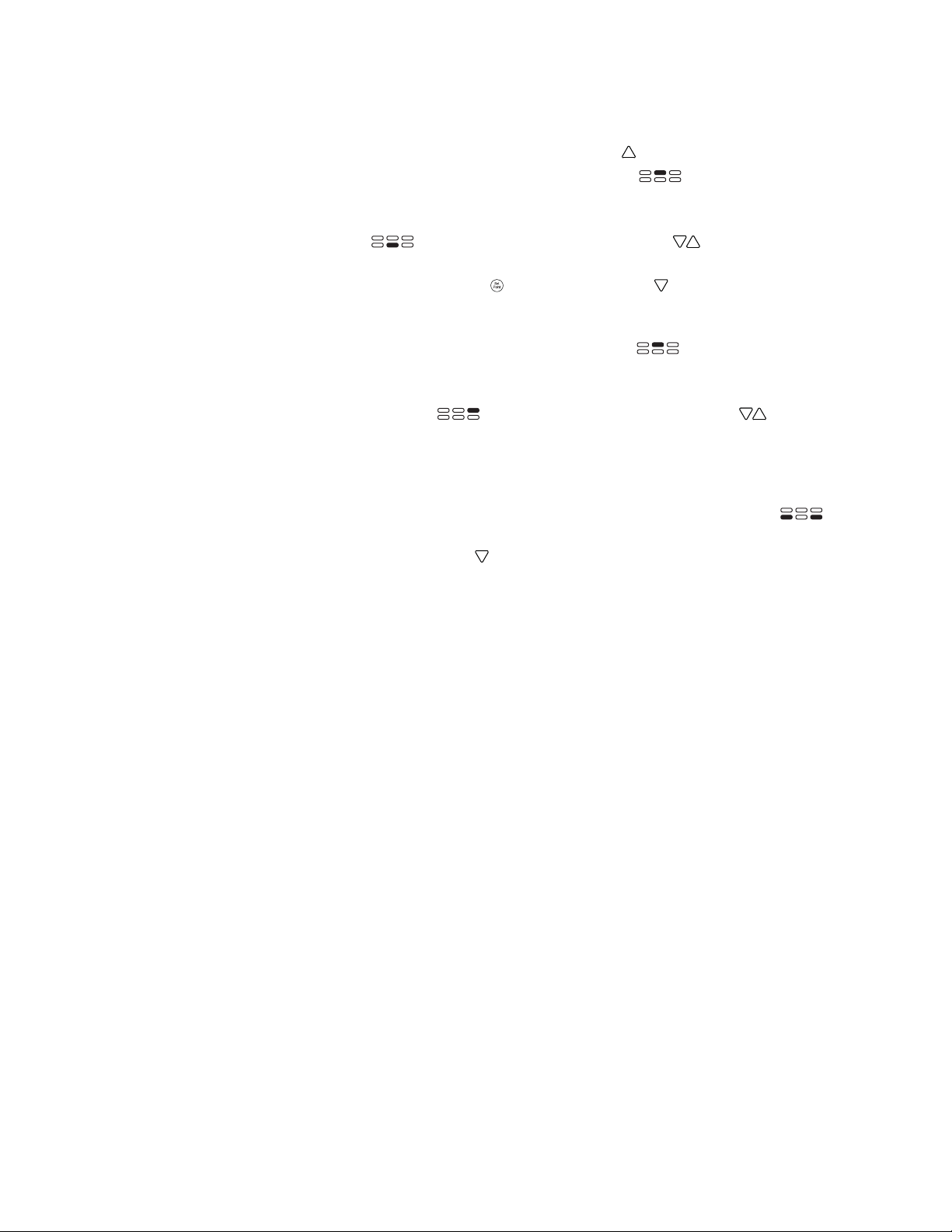
BAC-7001 or BAC-7051 with staged reheat and parallel fan
The standard programming in a BAC-7001 or BAC-7051 controller supports parallel
fan operation and staged reheat with the addition of a staging relay. An external
relay is also required for an AC fan circuit.
◆ The fan out relay switches a 24 volt AC pilot duty output.
◆ The analog reheat output at terminal AO1 varies between 0 and 10 volts DC to
control the staging relay.
For installation details, see the diagram Pressure independent BAC-7001 or BAC-7051
with staged reheat and parallel fan on page 49.
To configure the controller, see the topic Configuring for pressure independent VAV on
page 32.
Table 7-2 Bill of material for BAC-70x1 with staged reheat and parallel fan
REFERENCE PART # PART DESCRIPTION
DDC BAC-70X1 BACNET AAC FOR VAV, 3UI
ST STE-60XX-10 CHOOSE 6011 OR 6014 SPACE TEMP SENSOR MODEL
ST-C KMD-569X TEMP SENSOR PLENUM CABLE W/CONN.
AF SSS-100X AIRFLOW SENSOR, CHOOSE SIZE 'X' FROM DATA
NS1 KMD-1161 NETSENSOR
FAN REE-3112 12VDC Control Relay
HT3 REE-5001 3-STAGE RELAY CONTROLLER
TX XEE-6311-50 Control Transformer, 120/240/277/480VAC-24VAC,
KMC Controls
CHOOSE LENGTH
SHEET
50VA
48
Revision C
Page 49
BAC-7000 VAV Installation, applications, and operation
guide
Applications for BAC-7000 series VAV controllers
Pressure independent applications
Illustration 7-2 Pressure independent BAC-7001 or BAC-7051 with staged reheat and parallel fan
Revision C
49
Page 50

Applications for BAC-7000 series VAV controllers
Pressure independent applications
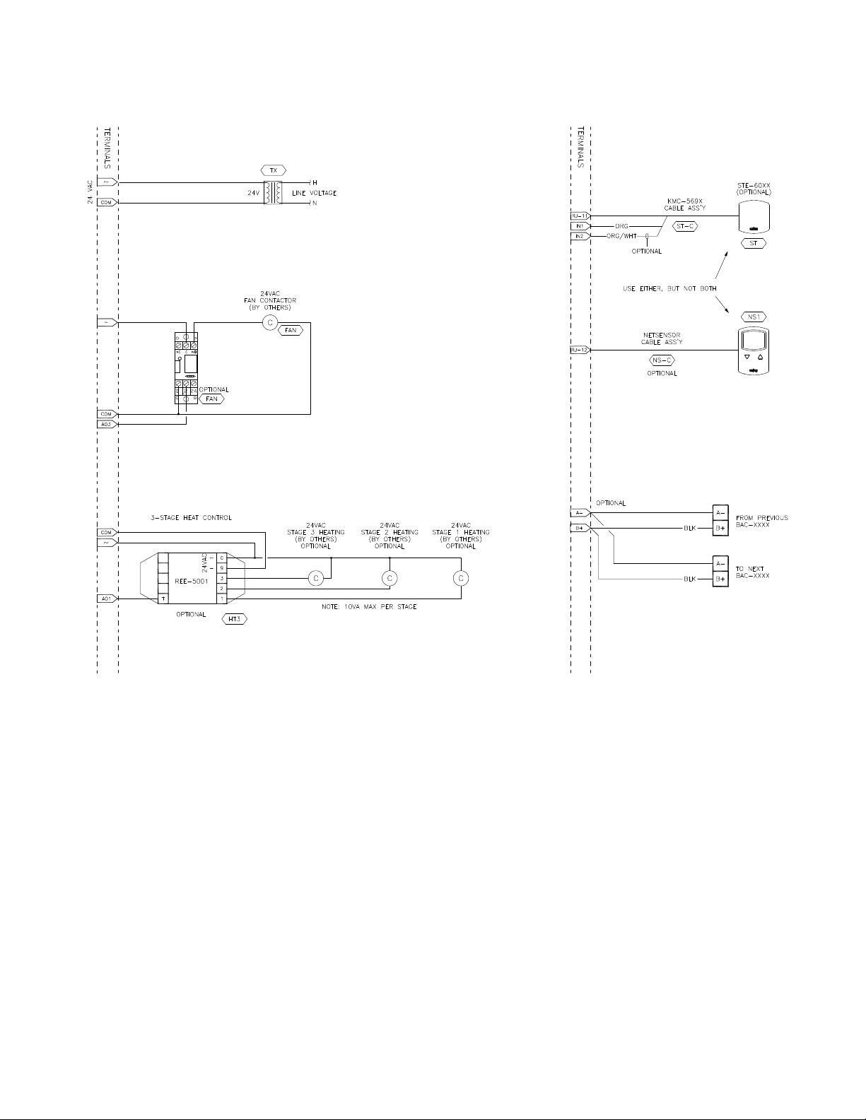
BAC-7003 or BAC-7053 with reheat and parallel fan
The standard programming in a BAC-7003 or BAC-7053 controller supports parallel
fan operation and On/Off reheat or modulating reheat. The BAC-7003 and
BAC-7053 controllers can directly control pilot duty switching for the fan and On/
Off reheat.
◆ The fan circuit is a 24 volt AC pilot duty output.
◆ The modulating option for reheat can control either an electric reheat unit with
an analog input or a modulating hot water valve. The analog reheat output at
output terminal AO1 varies between 0 and 10 volts DC.
◆ The On/Off reheat output is a 24-volt AC pilot duty output.
For connection details, see the diagram Pressure independent BAC-7003 or BAC-7053
with reheat and parallel fan on page 51.
To configure the controller, see the topic Configuring for pressure independent VAV on
page 32.
Table 7-3 Bill of materials for 70x3 with reheat and parallel fan
REFERENCE PART # PART DESCRIPTION
KMC Controls
DDC BAC-70X3 BACNET AAC FOR VAV, 1UI, 1 TRIAC, 1 N.O. RELAY
AF SSS-100X AIRFLOW SENSOR, CHOOSE SIZE 'X' FROM DATA
SHEET
ST STE-60XX-10 CHOOSE 6011 OR 6014 SPACE TEMP SENSOR MODEL
ST-C KMD-569X TEMP SENSOR PLENUM CABLE W/CONN.
CHOOSE LENGTH
AF SSS-100X AIRFLOW SENSOR, CHOOSE SIZE 'X' FROM DATA
SHEET
ST STE-60XX-10 CHOOSE 6011 OR 6014 SPACE TEMP SENSOR
MODEL
NS1 KMD-1161 NETSENSOR
TX XEE-6311-50 Control Transformer, 120/240/277/480VAC-24VAC,
50VA
50
Revision C
Page 51
BAC-7000 VAV Installation, applications, and operation
guide
Applications for BAC-7000 series VAV controllers
Pressure independent applications
Illustration 7-3 Pressure independent BAC-7003 or BAC-7053 with reheat and parallel fan
Revision C
51
Page 52

Applications for BAC-7000 series VAV controllers
Pressure independent applications
BAC-7003 or BAC-7053 staged reheat and parallel fan
The standard programming in a BAC-7003 or BAC-7053 controller supports parallel
fan operation and staged reheat with the addition of a staging relay. The BAC-7003
and BAC-7053 controllers can directly control pilot duty switching for the fan.
◆ The fan circuit is a 24 volt AC pilot duty output.
◆ The analog reheat output at terminal AO1 varies between 0 and 10 volts DC to
control the staging relay.
For connection details, see the diagram Pressure independent BAC-7003 or BAC-7053
with staged reheat and parallel fan on page 53.
To configure the controller, see the topic Configuring for pressure independent VAV on
page 32.
Table 7-4 Bill of material for BAC-70x1 with staged reheat and parallel fan
REFERENCE PART # PART DESCRIPTION
DDC BAC-70X3 BACNET AAC FOR VAV, 1UI, 1 TRIAC, 1 N.O. RELAY
ST STE-60XX-10 CHOOSE 6011 OR 6014 SPACE TEMP SENSOR MODEL
ST-C KMD-569X TEMP SENSOR PLENUM CABLE W/CONN.
AF SSS-100X AIRFLOW SENSOR, CHOOSE SIZE 'X' FROM DATA
NS1 KMD-1161 NETSENSOR
HT3 REE-5001 3-STAGE RELAY CONTROLLER
TX XEE-6311-50 Control Transformer, 120/240/277/480VAC-24VAC,
KMC Controls
CHOOSE LENGTH
SHEET
50VA
52
Revision C
Page 53

BAC-7000 VAV Installation, applications, and operation
guide
Applications for BAC-7000 series VAV controllers
Pressure independent applications
Illustration 7-4 Pressure independent BAC-7003 or BAC-7053 with staged reheat and parallel fan
Revision C
53
Page 54

Applications for BAC-7000 series VAV controllers
Pressure dependent applications
KMC Controls
Pressure
dependent
applications
The standard applications in a BAC-7000 series VAV controller support the
following pressure dependent VAV applications.
◆ BAC-7001 or BAC-7051 pressure dependent with single reheat on page 54
◆ BAC-7003 or BAC-7053 pressure dependent with single reheat on page 56
◆ Pressure dependent with staged reheat on page 58
For pressure independent applications, see the topic Pressure independent applications
on page 46.
BAC-7001 or BAC-7051 pressure dependent with single reheat
The standard programming in a BAC-7001 or BAC-7051 controller supports On/Off
reheat or modulating reheat. An external relay is required for the On/Off reheat AC
circuit.
◆ The modulating option for reheat can control either an electric reheat unit with
an analog input or a modulating hot water valve. The analog reheat output at
terminal AO1 varies between 0 and 10 volts DC.
◆ The the On/Off reheat output switches a relay for 24 volt AC pilot duty.
To enable pressure dependent programming, see the procedure in the topic,
Configuring for pressure dependent VAV on page 33.
Table 7-5 Bill of material for BAC-70x1 with single reheat
REFERENCE PART # PART DESCRIPTION
DDC BAC-70X1 BACNET AAC FOR VAV, 3UI
AF SSS-100X AIRFLOW SENSOR, CHOOSE SIZE 'X' FROM DATA
SHEET
ST STE-60XX-10 CHOOSE 6011 OR 6014 SPACE TEMP SENSOR MODEL
ST-C KMD-569X TEMP SENSOR PLENUM CABLE W/CONN.
CHOOSE LENGTH
NS1 KMD-1161 NETSENSOR
HT1 REE-3112 12VDC Control Relay
TX XEE-6311-50 Control Transformer, 120/240/277/480VAC-24VAC,
50VA
54
Revision C
Page 55
BAC-7000 VAV Installation, applications, and operation
guide
Applications for BAC-7000 series VAV controllers
Pressure dependent applications
Revision C
Illustration 7-5 Pressure dependent BAC-7001 or BAC-7051 with single reheat
55
Page 56

Applications for BAC-7000 series VAV controllers
Pressure dependent applications
BAC-7003 or BAC-7053 pressure dependent with single reheat
The standard programming in a BAC-7003 or BAC-7053 controller On/Off or
modulating reheat. An external relay is not required to switch 24-volt AC devices.
◆ The modulating option for reheat can control either an electric reheat unit with
an analog input or a modulating hot water valve. The analog reheat output at
output terminal AO1 varies between 0 and 10 volts DC.
◆ The On/Off reheat output is a 24-volt AC pilot duty output.
To enable pressure dependent programming, see the procedure in the topic,
Configuring for pressure dependent VAV on page 33.
Table 7-6 Bill of materials for 70x3 with reheat
REFERENCE PART # PART DESCRIPTION
DDC BAC-70X3 BACNET AAC FOR VAV, 1UI, 1 TRIAC, 1 N.O. RELAY
AF SSS-100X AIRFLOW SENSOR, CHOOSE SIZE 'X' FROM DATA
ST STE-60XX-10 CHOOSE 6011 OR 6014 SPACE TEMP SENSOR MODEL
ST-C KMD-569X TEMP SENSOR PLENUM CABLE W/CONN.
AF SSS-100X AIRFLOW SENSOR, CHOOSE SIZE 'X' FROM DATA
ST STE-60XX-10 CHOOSE 6011 OR 6014 SPACE TEMP SENSOR
NS1 KMD-1161 NETSENSOR
TX XEE-6311-50 Control Transformer, 120/240/277/480VAC-24VAC,
KMC Controls
SHEET
CHOOSE LENGTH
SHEET
MODEL
50VA
56
Revision C
Page 57
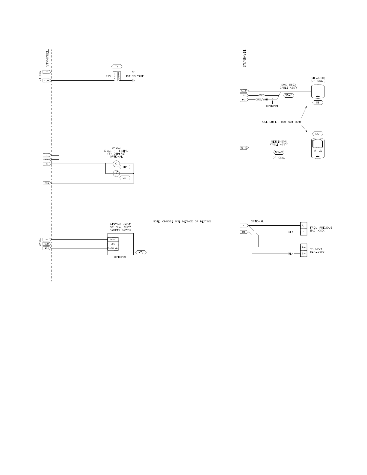
BAC-7000 VAV Installation, applications, and operation
guide
Applications for BAC-7000 series VAV controllers
Pressure dependent applications
Revision C
Illustration 7-6 Pressure dependent BAC-70x3 with reheat
57
Page 58

Applications for BAC-7000 series VAV controllers
Pressure dependent applications
Pressure dependent with staged reheat
The standard programming in a BAC-7003 or BAC-7053 controller supports staged
reheat with the addition of a staging relay. The analog reheat output at terminal AO1
varies between 0 and 10 volts DC to control the staging relay.
To enable pressure dependent programming, see the procedure in the topic,
Configuring for pressure dependent VAV on page 33.
Table 7-7 Bill of material for BAC-70x1 with staged reheat and parallel fan
REFERENCE PART # PART DESCRIPTION
DDC BAC-70X1 BACNET AAC FOR VAV, 3UI
DDC BAC-70X3 BACNET AAC FOR VAV, 1UI, 1 TRIAC, 1 N.O. RELAY
ST STE-60XX-10 CHOOSE 6011 OR 6014 SPACE TEMP SENSOR MODEL
ST-C KMD-569X TEMP SENSOR PLENUM CABLE W/CONN.
AF SSS-100X AIRFLOW SENSOR, CHOOSE SIZE 'X' FROM DATA
NS1 KMD-1161 NETSENSOR
HT3 REE-5001 3-STAGE RELAY CONTROLLER
TX XEE-6311-50 Control Transformer, 120/240/277/480VAC-24VAC,
KMC Controls
CHOOSE LENGTH
SHEET
50VA
58
Revision C
Page 59
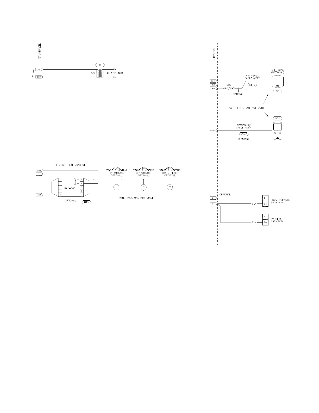
BAC-7000 VAV Installation, applications, and operation
guide
Applications for BAC-7000 series VAV controllers
Pressure dependent applications
Illustration 7-7 Pressure dependent BAC-7000 series VAV controller pressure dependent staged reheat
Revision C
59
Page 60

Applications for BAC-7000 series VAV controllers
Pressure dependent applications
KMC Controls
60
Revision C
Page 61

BAC-7000 VAV Installation, applications, and operation guide
Caution
SECTION 8
Reference to objects and programs
The following topics list the BACnet objects and Control Basic
programs are supplied with the controllers. These are advanced
reference topics for control technicians and engineers.
The BAC-7000 VAV controllers are BACnet Advanced Application Controlles (AAC)
and are composed of standard BACnet objects. This section lists the objects that are
likely to be monitored by a standard BACnet operator workstation to verify system
operation.
Input objects
Changing the configuration of any object or program may result in
unpredictable operation of a controller and damage to equipment that is under
control of a controller. See the topic Configuration and set up
on page 31 for
detailed instructions on object configuration in new controllers.
Topics in this section
◆ Input objects on page 61
◆ Output objects on page 62
◆ Value objects on page 62
◆ Loop objects on page 63
◆ Control Basic programs on page 64
The following BACnet input objects represent values at the physical inputs of the
controller. For wiring details, see the topics
Applications for BAC-7000 series VAV controllers on page 45.
Connecting inputs on page 18 and
Table 8-1 Input objects
Input Name Description Object type
AI1 ROOMTEMP Room Temperature KMC10K Type II
AI2 STESETPOINT STE Setpoint Table 4
AI3
AI4
DAT Discharge Air Temp KMC10K Type III
FLOWSNSR Airflow Sensor FPM 0-3000
Revision C 61
Page 62

Reference to objects and programs
Output objects
KMC Controls
Output objects
Value objects
The following BACnet output objects represent values at the physical outputs of the
controller. For wiring details, see the topics
Connecting outputs on page 19 and
Applications for BAC-7000 series VAV controllers on page 45.
Table 8-2 Output objects
Input Name Description Object type
AO1 ANALOG_HEAT Mod Heating 0-100%
BO2 BINARY_HEAT Binary Heat
BO3 FAN Fan Start
AO4 Damper Motor Drive MOTOR Volts 0-10
BACnet value objects represent setpoints or other operational conditions in the
controller.
Table 8-3 Analog Value objects
Object Name Description Units
AV1 SPACETEMP Space Temperature (auto) °F
AV2 SPACESSTPT Space Temp Setpoint °F
AV3 OFFSET Setpoint Offset °F
AV4 NS4_ActMinFlow User Button4 ActMinFlow cfm
AV5 NS5_MinSP User Button5 MinSP cfm
AV6 NS6_ActMaxFlow User Button6 ActMaxFlow cfm
AV7 NS7_MaxSP User Button7 MaxSP cfm
AV8 NS_MOTION Netsensor Motion
AV9 HTDMPRPOS PD Heat Damper Position %
AV10 --available--
AV11 STPT_MIN Setpoint Limit Min °F
AV12 STPT_MAX Setpoint Limit Max °F
AV13 STAT_DB Thermostat Deadband °F
AV14 --available--
AV15 --available--
AV16 LP1 Loop 1 (auto) ActiveSP% %
AV17 LP2 Loop 2 (auto) %
AV18 LP3 Loop 3 (auto) HtgSP% %
AV19 LP4 Loop 4 (auto) %
AV20 MIN_FLOW Minimum Flow cfm
AV21 MAX_FLOW Maximum Flow cfm
AV22 VOLFACTR Volume correction ft²
AV23 SNSRFACTR Sensor Correction (auto)
AV24 ACT_FLOW Actual Airflow (auto) ft/min
AV25 RQSTFLOW Requested Flow (auto) ft/min
AV26 ACTIVESP Active Temp Setpoint (auto) °F
AV27 VOLUME1 Duct Volume Readout (auto) cfm
62
Revision C
Page 63

BAC-7000 VAV Installation, applications, and operation
guide
Table 8-3 Analog Value objects (Continued)
Object Name Description Units
AV28 AUX_FLOW Auxillary Airflow cfm
AV29 HEAT_SP Heat Temperature °F
AV30 COOL_SP Cool Temperature Setpoint °F
AV31 DRV_TIME Damper Drive Time DRV_TIME
AV32 DMPR_POS Damper Position (auto) %
AV33 --available--
AV34 --available--
AV35 --available--
AV36 ACTFLOWMIN Actual Flow at Min cfm
AV37 ACTFLOWMAX Actual Flow at Max cfm
AV38 RQSTFLOWCFM Requested Flow Volume (auto) cfm
AV39 UNOCC_HTG_SP Unoccupied Heating Setpoin °F
AV40 UNOCC_CLG_SP Unoccupied Cooling Setpoint °F
Reference to objects and programs
Loop objects
Loop objects
Table 8-4 Binary value objects
Object Name Description Units
BV1 STANDBY Standby Mode Inactive/Active
BV2 UNOCC Unoccupied command Off/On
BV3 HEATING Changeover Mode Cool/Heat
BV4 CW_CLOSE Clockwise to Close No/Yes
BV5 REHEAT Reheat Status Disabled/Enabled
BV6 --available--
BV7 --available--
BV8 BALANCE Balancer OVRD Off/On
BV9 NETSENSOR NetSensor? Off/On
BACnet PID loops are used for modulating the damper and controlling reheat.
Table 8-5 Table 8–7 PID control loop objects
Loop Name Description Units
LOOP1 ACTSETCON Active Setpoint
LOOP2 FLWRQSTCON Flow Request
LOOP3 HTSETCON Heat Setpoint %
%
%
Revision C
63
Page 64

Reference to objects and programs
Control Basic programs
KMC Controls
Control Basic
programs
The following sections provide the Control Basic supplied with the controllers.
Program 1, 3, and 4 are configured to run automatically when the controller starts.
Table 8-6 Program objects
Automaticaly run
Program Name Description
1
2
3
4
5-10 --available-- No
SINGLEVAV Single Duct Pressure Indep VAV
SINGLEPRESS Single Duct Pressure Depend VAV
REHEAT Reheat (Mod & 2-Stg)
CALIB_UTIL Calibration Utility
on coldstart
Ye s
Ye s
Ye s
Ye s
Program 1—Pressure independent VAV
Program 1 configures the controller to run as a pressure independent VAV controller.
All input, output, value objects, and PID control loops are configured to support this
program. The program is configured to start automatically when the controller is
powered.
10 REM *** Pressure Independent BAC-70xx VAR 2.2 GS 5/27/14 ***
20 IF MODELNUMBER = 32 OR MODELNUMBER = 34 THEN AV31 = 300 ELSE
AV31 = 90
90 REM BALANCER OVRD
110 IF+ BV8 THEN S = AV2
130 IF- BV8 THEN START T , END
140 IF TIMEON( BV8 ) > 2:00:00 THEN BV8@8 = 0 , END
150 IF TIMEON( T ) > 20 THEN AV2@8 = S , STOP T , END
160 IF T THEN END
170 IF BV8 = 0 THEN GOTO 250
180 IF AV2 > 1 THEN AV2@8 = 1 : IF AV2 < 1 THEN AV2@8 = 0 : REM Bal
Limits
190 IF AV2 = 1 THEN AV25 = AV21 / AV22 ELSE AV25 = AV20 / AV22 :
REM Bal Flow Settings
200 GOTO 380
250 REM Temp SPs If no NetSensor use AI1 & AI2 (Not for STE-6012/
16)
260 BV9 = NETSENSORSTATUS
270 IF BV9 THEN GOTO 310
280 IF NOT BV9 THEN RLQ AV8@8
290 IF AI1 < 0 THEN RLQ AV1@8 , RLQ AV2@8 , GOTO 310 ELSE AV1@8 =
AI1 : REM Use Sensor if present
300 IF AI2 > 89 THEN GOTO 310 ELSE AV2@8 = AI2 : REM Use Setpoint
if present
310 IF BV3 THEN AV26 = AV29 ELSE AV26 = AV30
320 IF BV3 THEN A = 1 - AV16 / 100 ELSE A = AV16 / 100
330 AV2@8 = MIN( MAX( AV2 , AV11 ) , AV12 ) : REM Apply SP limits
340 IF BV1 = 0 THEN AV29 = AV2 - AV13 / 2 ELSE AV29 = AV2 - AV3
350 IF BV1 = 0 THEN AV30 = AV2 + AV13 / 2 ELSE AV30 = AV2 + AV3
355 IF BV2 = 1 THEN AV29 = AV39
356 IF BV2 = 1 THEN AV30 = AV40
64
Revision C
Page 65

BAC-7000 VAV Installation, applications, and operation
guide
360 REM Flow Calc (FPM & CFM)
370 AV25 = ( ( AV21 - AV20 ) * A + AV20 ) / AV22 : REM
RQSTFLOW(fpm)
380 AV24 = AI4 * AV23 : REM CORRECTED FPM
390 AV27 = AV24 * AV22 : REM CFM In
400 REM Damper Control
410 IF AV17 > 65 AND BV4 THEN START B
420 IF AV17 > 65 AND NOT BV4 THEN START C
430 IF AV17 < 35 AND BV4 THEN START C
440 IF AV17 < 35 AND NOT BV4 THEN START B
450 IF AV17 > 35 AND AV17 < 65 THEN STOP B , STOP C
460 IF B THEN STOP C
470 IF C THEN STOP B
480 X = 1 / SCANS
490 IF AV17 < 99 AND AV17 > 1 THEN GOTO 500 ELSE GOTO 560
500 IF AV17 < 36 OR AV17 > 64 THEN START D ELSE STOP D
510 IF TIMEON( D ) > 0:00:10 THEN GOTO 560
520 Y = X + Y
530 IF Y > 5 THEN Y = 0
540 Z = ABS( AV17 - 50 ) / 50
550 IF Y > Z THEN STOP B , STOP C
560 IF B THEN AO4 = 10
570 IF C THEN AO4 = 0
580 IF NOT B AND NOT C THEN AO4 = 5
590 IF AO4 > 7 THEN START G ELSE STOP G
600 IF AO4 < 3 THEN START H ELSE STOP H
610 IF TIMEON( G ) > 0:06:00 OR TIMEON( H ) > 0:06:00 THEN AO4 = 5
, START I ELSE STOP I
620 IF TIMEON( I ) > 0:06:00 THEN STOP G , STOP H , STOP B , STOP
C
630 IF BV4 AND AO4 < 3 THEN AV32 = AV32 + X * 100 / AV31
640 IF BV4 AND AO4 > 7 THEN AV32 = AV32 - X * 100 / AV31
650 IF NOT BV4 AND AO4 < 3 THEN AV32 = AV32 - X * 100 / AV31
660 IF NOT BV4 AND AO4 > 7 THEN AV32 = AV32 + X * 100 / AV31
670 IF AV32 > 100 THEN AV32 = 100
680 IF AV32 < 0 THEN AV32 = 0
690 END
Reference to objects and programs
Control Basic programs
Revision C
65
Page 66

Reference to objects and programs
Control Basic programs
Program 2—Pressure dependent VAV
Program 2 configures the controller to run as a pressure dependent VAV controller.
All input, output, value objects, and PID control loops are configured to support this
program. The program is not configured to run automatically when the controller is
powered. To change the controller to pressure dependent VAV, use a BACnet
operator workstation to halt Program 1 and start Program 2.
10 REM *** Pressure Dependent BAC-70xx VAR 2.2 GS 5/27/14 ***
80 REM Temp SPs If no NetSensor use AI1 & AI2 (Not for STE-6012/
16)
90 BV9 = NETSENSORSTATUS
100 IF BV9 THEN GOTO 140
110 IF NOT BV9 THEN RLQ AV8@8
120 IF AI1 < 0 THEN RLQ AV1@8 , RLQ AV2@8 , GOTO 140 ELSE AV1@8 =
AI1 : REM Use Sensor if present
130 IF AI2 > 89 THEN GOTO 140 ELSE AV2@8 = AI2 : REM Use Setpoint
if present
140 IF BV3 THEN AV26 = AV29 ELSE AV26 = AV30
150 AV2@8 = MIN( MAX( AV2 , AV11 ) , AV12 ) : REM Apply SP limits
160 IF BV1 = 0 THEN AV29 = AV2 - AV13 / 2 ELSE AV29 = AV2 - AV3
170 IF BV1 = 0 THEN AV30 = AV2 + AV13 / 2 ELSE AV30 = AV2 + AV3
KMC Controls
180 REM HEAT MODE
190 IF LOOP3 > 30 THEN START Q
200 IF LOOP3 < 1 THEN STOP Q
210 IF TIMEON( Q ) > 0:01:00 THEN START BV3 ELSE STOP BV3
220 REM CALIBRATE DAMPER
230 IF+ INT( TIME / 100 ) < 1 THEN START U
240 IF POWERLOSS THEN START U
250 IF TIMEON( U ) > AV31 THEN STOP U
260 IF U AND BV4 THEN AO4 = 0 , STOP BV3
270 IF U AND NOT BV4 THEN AO4 = 10 , STOP BV3
280 IF U OR BV3 THEN GOTO 520
290 REM Damper Control
300 IF AV16 > 70 THEN START C , STOP B
310 IF AV16 < 30 THEN START B , STOP C
320 IF AV16 > 35 AND AV16 < 65 THEN STOP B , STOP C
330 X = 1 / SCANS
340 IF AV16 < 99 AND AV16 > 1 THEN GOTO 350 ELSE GOTO 420
350 IF AV16 < 36 OR AV16 > 64 THEN START D ELSE STOP D
360 IF TIMEON( D ) > 0:00:10 THEN GOTO 420
370 REM The following will pulse the actuator as it nears
satisfied position to reduce overshoot
380 Y = X + Y : IF Y > 5 THEN Y = 0
390 Z = ABS( AV16 - 50 ) / 50
400 IF Y > Z THEN STOP B , STOP C
410 REM Drive Damper
420 IF B AND NOT BV4 THEN AO4 = 0 : REM Close damper CCW
430 IF B AND BV4 THEN AO4 = 10 : REM Close damper CW
440 IF C AND NOT BV4 THEN AO4 = 10 : REM Open damper CW
450 IF C AND BV4 THEN AO4 = 0 : REM Open damper CCW
460 IF NOT B AND NOT C THEN AO4 = 5 : REM Stop Damper
470 IF AO4 > 7 THEN START G ELSE STOP G : REM Check Drive Time
480 IF AO4 < 3 THEN START H ELSE STOP H : REM Check Drive Time
490 IF TIMEON( G ) > 0:06:00 OR TIMEON( H ) > 0:06:00 THEN AO4 = 5
, START I ELSE STOP I : REM Stop Driving Damper
500 IF TIMEON( I ) > 0:03:00 THEN STOP G , STOP H , STOP B , STOP
C : REM Allow Damper to be Driven
66
Revision C
Page 67

BAC-7000 VAV Installation, applications, and operation
guide
510 REM ESTIMATE DAMPER POSITION
520 P = 1 / SCANS
530 IF NOT BV4 AND AO4 < 3 THEN AV32 = AV32 - P * 100 / AV31
540 IF NOT BV4 AND AO4 > 7 THEN AV32 = AV32 + P * 100 / AV31
550 IF BV4 AND AO4 < 3 THEN AV32 = AV32 + P * 100 / AV31
560 IF BV4 AND AO4 > 7 THEN AV32 = AV32 - P * 100 / AV31
570 IF AV32 > 100 THEN AV32 = 100
580 IF AV32 < 0 THEN AV32 = 0
590 END
Program 3—Reheat
Program 3 configures the controller for a parallel fan and On/Off and modulating
reheat. The program is configured to start automatically when the controller is
powered. For custom reheat programming, halt this program and add custom
programming to Programs 5-10.
10 REM *** Reheat BAC-70xx VAR 2.2 GS 5/27/14 ***
20 REM ---------FAN POWERED 1-STAGE AND/OR MODULATING REHEAT
SEQUENCE---------30 REM Entire reheat sequence is easily disabled by toggling BV5
on-off.
40 REM Auxillary flow setpoint is used if AUXILLARY FLOW( AV28 ) >
MIN FLOW( AV20 )
Reference to objects and programs
Control Basic programs
50 IF BV5 THEN GOTO 90
60 AO1 = 0 : STOP BO2
70 IF TIMEOFF( BO2 ) > 0:00:30 THEN STOP BO3
80 END : REM If no reheat then stop
90 REM Reheat With Fan
100 AO1 = AV18 : REM Modulating Valve
110 IF AV18 > 50 THEN BO2 = 1 , AO1 = LOOP3 : REM Start Reheat
120 IF AV18 < 5 THEN BO2 = 0 , AO1 = 0 : REM Stop Reheat
130 IF AO1 > 10 OR BO2 = 1 THEN BO3 = 1
140 IF BV8 = 1 THEN GOTO 160
150 IF AO1 > 10 OR BO2 = 1 THEN AV25 = MAX( AV20 , AV28 ) / AV22
160 IF AO1 < 5 AND TIMEOFF( BO2 ) > 0:00:30 THEN STOP BO3 : REM
STOP FAN
170 END
Program 4—Calibration
Program 4 calculates airflow correction factors for the balancing routine. This
program is only required for pressure independent VAV control.
10 REM *** Calibration BAC-70xx VAR 2.2 GS 5/27/14 ***
20 REM -- NetSensor Buttons --
30 IF POWERLOSS THEN GOTO 230
40 IF BV8 = 0 THEN GOTO 110
50 REM Balancing Mode
60 AV20@8 = AV5 : REM AV20 = MinCFMSP Btn 5
70 AV21@8 = AV7 : REM AV21 = MaxCFMSP Btn 7
80 AV36@8 = AV4 : REM AV36 = ActualMinCFM Btn 4
90 AV37@8 = AV6 : REM AV37 = ActualMaxCFM Btn 6
100 GOTO 160
Revision C
67
Page 68

Reference to objects and programs
Control Basic programs
110 REM Normal Mode
120 AV5@8 = AV20 : REM MinCFMSP Btn 5 = AV20
130 AV7@8 = AV21 : REM MaxCFMSP Btn 7 = AV21
140 AV4@8 = AV36 : REM ActualMinCFM Btn 4 = AV36
150 AV6@8 = AV37 : REM ActualMaxCFM Btn 6 = AV37
160 REM Calculate SensorCorrection AV23 (using AV36 & AV37 values
)
170 H = AV37 / AV21 : L = AV36 / AV20
180 AV23 = ( AV38 - AV20 ) * ( H - L ) / ( AV21 - AV20 ) + L
190 REM Calculate Requested Flow in CFM
200 AV38 = AV25 * AV22 : REM RQSTFLOW in CFM..AV38 for display on
graphics
210 AV36@10 = AV20 : AV37@10 = AV21 : REM Sets temporary values
220 END
230 REM ------ Saves Balance Data After Power loss ----240 IF ABS( AV6 - 150 ) > 0.5 THEN AV37@8 = AV6
250 IF ABS( AV4 - 50 ) > 0.5 THEN AV36@8 = AV4
260 END
KMC Controls
68
Revision C
Page 69

BAC-7000 VAV Installation, applications, and operation guide
Index
A
accessories 10
actuator specifications
airflow sensor
connecting
sequence of operation
specifications
airflow setpoint configuration
applications
pressure dependent
pressure independent
automatic network address
auxiliary airflow configuration
23
45
8
39
8
54
46
31
B
BACnet objects 61
inputs
61
loops
63
output
value
balancing
balancing sequence
baud
bulbs
network isolation
replacement
62
62
35
43
31
27
10
C
changeover sequence 41
clockwise to close
communications LED
conduit connections
configuration
airflow setpoints
auxiliary airflow 33
damper direction to close
network addresses
pressure dependent 33
pressure independent
reheat
33
temperature sepoint limits 33
volume correction factor
Control Basic programs
balancing and calibration
pressure dependent VAV 66
pressure independent VAV
reheat and fan
32
25
17
31
33
32
31
32
32
64
67
67
33
33
64
D
damper
direction to close
manual position
operation sequence
position indicator
position sequence
shaft size
device instance
dimensions
direction to close the damper
8
9
32
27
42
25
42
31
E
end-of-line switches 22
F
fan operation, sequence 42
I
inputs
as BACnet objects
NetSensor
pull-up
specifications
wiring
20
18
18
61
6
L
LED
communications
ready
25
loop objects
63
25
M
MAC address 31
maintenance
MS/TP
specifications
termination 21
wiring
30
7
21
N
NetSensor
as a balancing tool
as an input
detecting
wiriing
20
39
20
35
32
Revision C 69
Page 70

KMC Controls
network
addresses
disconnect switch
end-of-line
isolation bulbs
termination
wiring
31
25
22
27
22
21
O
occupancy sequence 40
operation
outputs
as BACnet objects
by model
specifications
wiring
25
62
6
6
19
P
PID loops
as BACnet objects
sequence of operation
power supply
requirements
wiring
pressure dependent
applications
configuration
pressure independent
applications
configuration
pull-up resistors
23
63
8
54
33
46
32
18
41
S
sequences of operation 39, 40
airflow sensor
balancing
changeover
damper
fan operation
input sources
NetSenor
occupancy
PID loops
pressure dependent
pressure independent
reheat
42
standby
specifications
actuator
airflow sensor
dimensions
inputs
6
MS/TP
network
outputs
power supply
speed of rotation
standby sequence
stop pins
14
39
43
41
42
42
39
39
40
41
41
41
40
6
8
8
9
7
7
6
8
8
40
T
temperature setpoints 40
termination for MS/TP
21
R
ready LED 25
reheat
configuration
sequence
replacement parts
rotation
limits
speed 8
42
14
33
10
V
value objects 62
volume correction factor
W
wiring 17
inputs
18
MS/TP
NetSensor
outputs 19
power supply
21
20
23
32
Revision C70
 Loading...