

Page 1
Applications Guide
BAC-5051E router
Includes installation, operation, and maintenance instructions
Revision J
Page 2

KMC Controls, Inc.
Copyrights and trademarks
©2018, KMCControls, Inc.
NetSensor, WinControl, and the KMC logo are registered trademarks of KMC Controls, Inc.
AppStat, BACstage, FlexStat, FullBAC, KMC Connect, KMC Connect Lite, KMC Converge,
KMC Converge GFX, KMC Conquest, TotalControl, SimplyVAV, and the SimplyVAV logo are
trademarks of KMC Controls, Inc.
All rights reserved. No part of this publication may be reproduced, transmitted, transcribed,
stored in a retrieval system, or translated into any language in any form by any means
without the written permission of KMC Controls, Inc.
Printed in U.S.A.
The material in this manual is for information purposes only. The contents and the product it
describes are subject to change without notice. KMC Controls, Inc. makes no
representations or warranties with respect to this manual. In no event shall KMC Controls,
Inc. be liable for any damages, direct or incidental, arising out of or related to the use of this
manual.
Handling precautions
To prevent damage from electrostatic discharges, take reasonable precautions when
handling, servicing, or installing the router. Discharge accumulated static electricity by
touching your hand to a securely grounded object before working with the router.
KMC Controls, Inc.
19476 Industrial Drive
New Paris, IN 46553
U.S.A.
TEL: 1.574.831.5250
FAX: 1.574.831.5252
info@kmccontrols.com
2 Revision J
Page 3

BAC-5051E Router Contents
C o n t e n t s
Contents 3
Section 1: Introduction 5
Specifications 5
Accessories and replacement parts 7
Mounting the router 8
Connecting for network routing 8
MS/TP network wiring 9
MS/TP EOL (End-Of-Line) termination switches 9
Connecting power 9
Single-cable connection 11
Maintenance 12
If you encounter difficulty 12
Safety considerations 12
Using the router for a technician's service tool 13
Section 2: Configuring the BAC-5051E router 15
Initial setup 15
Set up for configuration 16
Logging in 16
Changing your computer's address 18
Device properties page 21
Time page 22
BACnet Time Sync Networks 23
SNTP Time Server 24
Daylight Saving Time 24
Security page 24
Session timeout 26
Section 3: Setting up routing 27
BACnet IP routing 27
BACnet foreign device routing 28
BACnet Broadcast Management Device routing 30
Network address translation 31
Table 31
BACnet PAD routing 32
BACnet Ethernet routing 33
MS/TP configuration 34
Router Core properties page 35
Home Port 35
Routing properties 36
Section 4: Diagnostics and status 37
Routing Status page 37
Route Status buttons 38
Route Status list 39
Purging the Route Status list 41
Device Status page 42
Token Use page 44
MS/TP Metrics page 46
Interpreting the diagnostic data 46
Revision J 3
Page 4

Contents KMC Controls, Inc.
Description of the Metrics page 48
MS/TP Capture page 49
Section 5: Advanced features 51
Recovering the network address 51
Updating the firmware 53
Configure from a file 54
VAV balancing and configuration 55
VAV balancing 55
Configuring VAV setpoints 56
Commanding and monitoring airflow 57
Index 59
4 Revision J
Page 5

BAC-5051E Router Section 1: Introduction
Sec tion 1: Introduction
This section provides a description of the KMC Controls BAC-5051E router. It also
introduces safety information. Review this material before installing or operating the
router.
The KMC Controls BAC–5051E is a multi-port BACnet router. Router highlights are:
l Easy to install and simple to configure.
l Configured from internally served web pages.
l Internal network diagnostics and route status reports.
Topics in this section
Specifications 5
Accessories and replacement parts 7
Mounting the router 8
Connecting for network routing 8
Connecting power 9
Single-cable connection 11
Maintenance 12
If you encounter difficulty 12
Safety considerations 12
Using the router for a technician's service tool 13
Specifications
Specifications are subject to change without notice.
Communication ports
BACnet Ethernet and IP
10BaseT/100BaseT, RJ–45 connector
BACnet MS/TP
One optically isolated MS/TP port, 9.6–115.2kilobaud
Removable three-screw terminal block, 12–22 AWG wire
Switched end-of-line termination
USB
USB micro B connection for temporary power
Configuration and software
All configuration is through internal browser based configuration pages. Requires HTML5
browser.
Revision J 5
Page 6

Section 1: Introduction KMC Controls, Inc.
BACnet routing
BACnet IP–Two ports each of that can be set up for any of the following protocols:
l Normal BACnet IP network routing
l BACnet broadcast management device with network and port address translation
l Foreign device registration with BACnet broadcast management devices (BBMD)
l PAD (packet assembling/disassembling) routing
One BACnet Ethernet port
One MS/TP port
Installation
Supply voltage 24 VAC (50/60 Hz) or 24 VDC; –15%, +20%; Class2 only; non-
supervised (all circuits, including supply voltage, are power
limited circuits)
5 volts DC from powered USB connection
Supply source automatically switches to highest available
voltage
8 VA required power
Weight Approximately 5.3 ounces (149 grams)
Case material Green and black flame retardant plastic
Processor and memory
Processor Processor 32-bit ARM® Cortex-M4
Memory Configuration parameters and diagnostics are stored in
nonvolatile memory; auto restart on power failure
Regulatory and agency listings
BTL Listed as BACnet Testing Laboratory profile B-RTR.
UL UL 916 Energy Management Equipment
RoHS RoHS compliant (pending)
CE CE compliant
FCC FCC Class A, Part 15, Subpart B and complies with Canadian
ICES-003 Class A
This device complies with part 15 of the FCC Rules. Operation
is subject to the following two conditions: (1) This device may
not cause harmful interference, and (2) this device must accept
any interference received, including interference that may
cause undesired operation.
Environmental limits
Operating Temperature 32 to 120° F (0 to 49° C)
Shipping Temperature -40 to 140° F (–40 to 60° C)
Humidity 0–95% RH, non-condensing
6 Revision J
Page 7
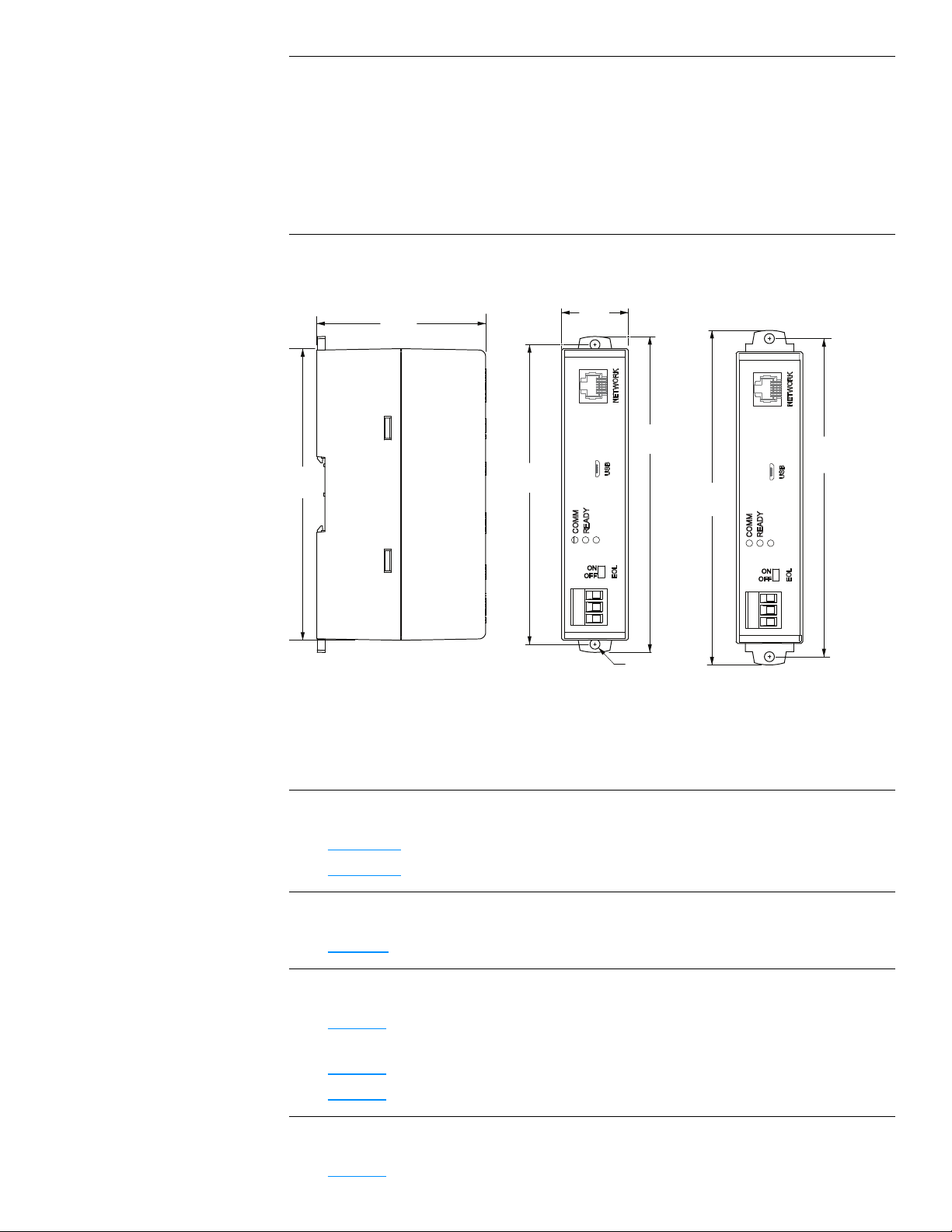
5.64 in.
143 mm
1.25 in.
38 mm
6.31 in.
160 mm
6.00 in.
152 mm
Ø .187 in.
4.8 mm
5.50 in.
140 mm
5.95 in.
151 mm
3.16 in.
80 mm
BAC-5051E Router Section 1: Introduction
Timekeeping
The BAC-5051E router is a BACnet time master device.
Update interval Daily, weekly, or monthly
Time message type UTC, local, or both
Setting time Synchronized to SNTP server, set from computer time, or
manually entered
Dimensions and mounting
Surface mount or 35 x 7.5 mm DIN rail mounting
Accessories and replacement parts
The following accessories and replacement parts are available from KMC Controls, Inc.
Power transformer
XEE-6111-50
XEE-6112-50
Surge suppressors
KMD-5567
Cables
HPO-5551
HSO-9001
HSO-9011
Replacement parts
HPO-9901
Revision J 7
Transformer, 120-to-24 VAC, 50 VA, single-hub
Transformer, 120-to-24 VAC, 50 VA, dual-hub
EIA-485 surge suppressor for MS/TPor Tier 2 networks
Conquest Router Tech Cable Kit–Includes USB, Ethernet, and
MS/TP to NetSensor cables
Ethernet cable, 50 feet
Ethernet cable, 50 feet, plenum rated
Controller replacement parts kit with terminal blocks and DIN clip
Page 8
Extend mounting tabs
6.00 in.
152 mm
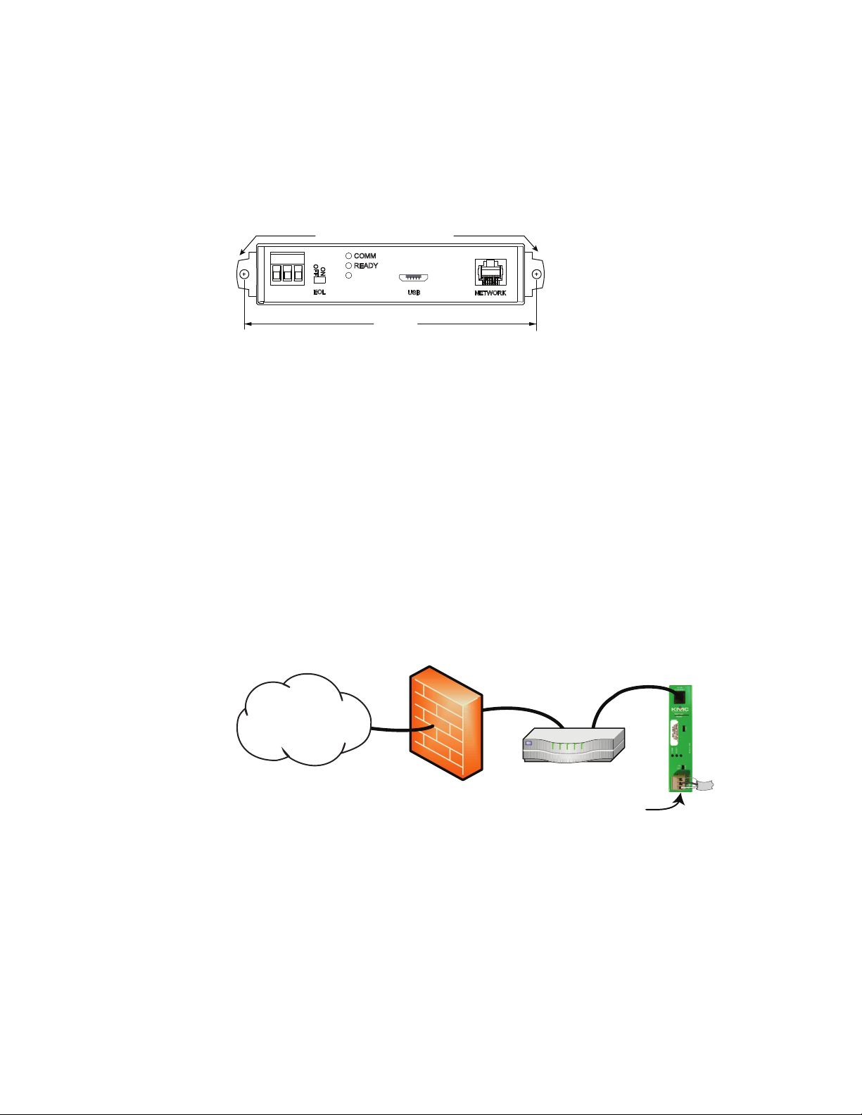
Internet
Firewall
Network router
BAC-5051E
24 volts (on end)
MS/TP
Section 1: Introduction KMC Controls, Inc.
Mounting the router
For permanent installations, the router can be flush mounted or snapped to a 35 x 75 mm
DIN rail. For router dimensions, see the topic Specifications on page 5.
Surface mounting Extend the mounting tabs away from the router body and fasten with
screws.
Illustration 1–1 Surface mounting the router
DIN rail mounting Mount the DIN rail and then do the following:
1 Extend the mounting tabs.
2 Place the bottom of the router over the DIN rail.
3 Push the mounting tabs back toward the router body to lock it to the rail.
Connecting for network routing
For permanent installations, connect the BAC-5051E router to a network router or network
switch and an MS/TP network. For permanent installations, the router is typically connected
to a 24 volt transformer for power.
For installations that include Internet access, install the router behind a firewall.
Illustration 1–2 Permanent installation
See also the following topics:
l Mounting the router on page 8
l Connecting power on page 9
8 Revision J
Page 9

-A +B S
-A +B S
End of segment
Middle of segment
BAC-5051E Router Section 1: Introduction
MS/TP network wiring
Use the following principles when connecting the router to an MS/TP network:
l Connect no more than 128 BACnet devices to one MS/TP network. The devices can be
any mix of masters, slaves, or routers.
l Use twisted pair, shielded cable with capacitance of no more than 51picofarads per
foot for all network wiring. Belden cable #82760 or equivalent meets the requirements.
l Connect the -A terminal in parallel with all other - terminals.
l Connect the +B terminal in parallel with all other + terminals.
l Connect the shields of the cable together at each mid line device. For KMC BACnet
devices use the S terminal.
l Connect the shield to an earth ground at one end only.
l Use a repeater between every 32 MS/TP devices or if the cable length exceeds 4,000
feet (1,220 meters). Use no more than four repeaters per MS/TP network.
l Place a KMD-5567 surge suppressor in the MS/TP cable where it exits a building.
Illustration 1–3 MS/TPwiring
MS/TP EOL (End-Of-Line) termination switches
The controllers on the physical ends of the MS/TP wiring segment must have end-of-line
termination added for proper network operation.
l If the router is at the end of the network segment, set the EOL switch to ON.
l If the router is in the middle of the network segment, set the EOL switch to OFF.
Connecting power
Power the BAC-5051E router from a 24 volt power source, either AC or DC, or from a USB
connection. The router begins to operate when a power source is applied. Use the following
guidelines when choosing and wiring sources to the router.
Revision J 9
Page 10
USB power
24 volts AC 24 volts DC
Section 1: Introduction KMC Controls, Inc.
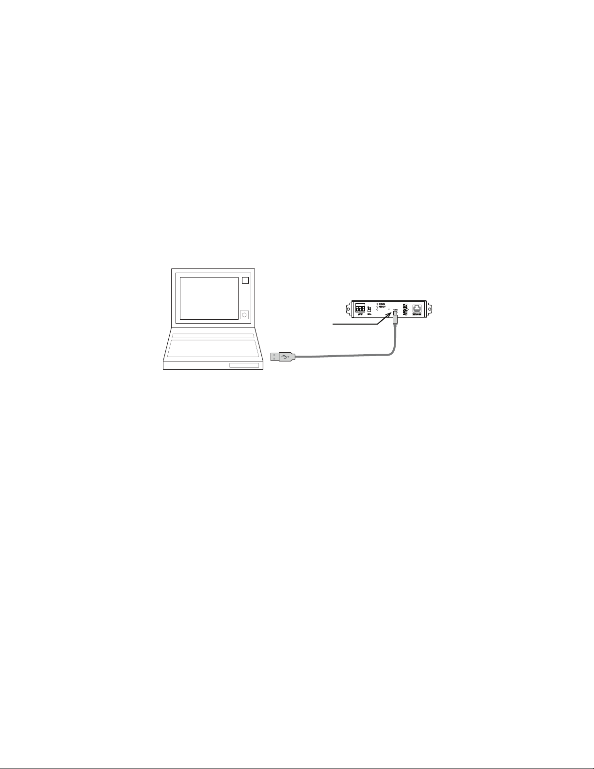
For USB power Connect the router to a powered USB port with a USB A to USB micro B
cable. Typically the USB ports on laptop computers can supply power to the router. When
connecting to a USB hub, verify the power specifications of the hub. See the topic
Specifications on page 5.
Illustration 1–4 USB connection
Note: When using USB connection for power and communications, use the USB cable from the
HPO-5551 Technician's Router Cable Kit. The cable from the kit is specified to supply
enough power for both the USB and the networkconnection.
To use the USB for power and networkcommunications, see the topic Single-cable
connection on page 11.
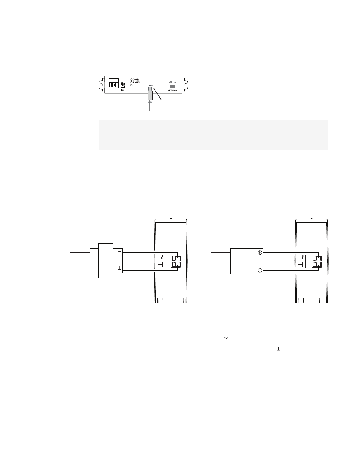
For permanent installations, the router is usually powered from a 24 volt transformer or DC
power supply.
Illustration 1–5 24 volt power connections
For 24 volt AC power Connect a 24 volt transformer to the black power terminal block on the
end of the router.
l Connect the AC phase to the phase terminal .
l Connect the ground side of the transformer to the ground terminal .
l Use a Class2 transformer of the appropriate size to supply power to the router.
l KMC Controls recommends powering the router from a dedicated transformer.
l Do not run 24 volt power from within an enclosure to external devices.
10 Revision J
Page 11
Computer with
browser or
service tool
USB-A to
USB-micro
cable
BAC-5051E Router Section 1: Introduction
For 24 volt DC power Connect a 24 volt power supply to the black power terminal block on
the end of the router.
l Connect the positive terminal (+) to the phase terminal .
l Connect the negative terminal (-) of the power supply to the ground terminal .
l Use a Class2 power supply of the appropriate size to supply power to the router.
l KMC Controls recommends powering the router from a dedicated power supply.
l Do not run 24 volt power from within an enclosure to external devices.
Single-cable connection
The single-cable connection method connects the BAC-5051E router to a computer with a
USB cable that supplies both power and communications. The USB port becomes a virtual
network interface card (NIC) and establishes a network between the computer and the
router.
Note: Use the USB cable from the HPO-5551 Router Technician's Cable kit for a single cable
connection. This cable meets the specification to supply the power and communications
required by the router. Other cables may prevent routing on one or more ports.
Illustration 1–6 Single-cable connection
To set up a single-cable connection, do the following:
1 Plug the USB cable from the HPO-5551 cable kit into the router.
2 Plug the other end of the USB cable into the computer.
Depending on the version of Windows, the first time the router is plugged into a
computer, Windows will display a message that it is installing a new driver. Click on the
message to see more details. Note the name of the device in the message because
you will need this information in later steps. Allow the installation to finish and then
close the dialog.
Revision J 11
3 From the Windows Control Panel, click Network and Internet and then Networking
Sharing Center.
4 Once the center is open, click Change Adaptor Settings.
5 Identify the Local Area Connection that is associated with the router and click it to
open the connection.
6 In the Local Area Connection status, click Properties.
Page 12

Section 1: Introduction KMC Controls, Inc.
7 When the next dialog opens, choose Internet Protocol Version 4 and then click
Properties.
8 In the Properties dialog, select Use the following IPaddress and then enter a unique
IPaddress and subnet mask.
l The IP address must be unique and be part of the same subnet as the router’s
address.
l If the router is still configured with the default address, use 192.168.1.252.
l Set the subnet mask to 255.255.0.0.
9 When finished, click OK to save the work and then close all dialog boxes.
To test the connection, do the following:
1 Open a browser window.
2 Enter the address of the router.
3 When the log in page opens, set up the router as described in the topic Setting up
routing on page 27.
See also the topic, Using the router for a technician's service tool on page 13.
Maintenance
The BAC-5051E router requires no routine maintenance. If necessary, clean with a damp
cloth and mild soap.
If you encounter difficulty
If you experience difficulty with the BAC-5051E router, KMC Controls provides the following
assistance.
The KMC Controls web siteNavigate to the support section on the KMC controls web site
for the latest information for BAC-5051E router and other KMC Controls products.
www.kmccontrols.com
KMC technical supportOur distribution partners have unlimited and free access to our team
of Technical Support representatives. We provide coast-to-coast and toll-free support from
8:00 AM Eastern to 5:00 PM Pacific time.
Toll-Free Technical Support: (866) 303-4562
Safety considerations
KMC Controls, Inc. assumes the responsibility for providing you a safe product and safety
guidelines during its use. Safety means protection to all individuals who install, operate, and
service the equipment as well as protection of the equipment itself. To promote safety, we
use hazard alert labeling in this manual. Follow the associated guidelines to avoid hazards.
12 Revision J
Page 13
Caution
Computer with
service tool
NetSensor and device on
permanent MS/TP network
Service tool
router
MS/TP to NetSensor cable
USB-A to
USB-micro
cable
BAC-5051E Router Section 1: Introduction
Caution indicates potential personal injury or
equipment or property damage if instructions
are not followed.
Note: Provides additional information that is important but may be missed.
Tip: Provides programing tips and shortcuts that may save time.
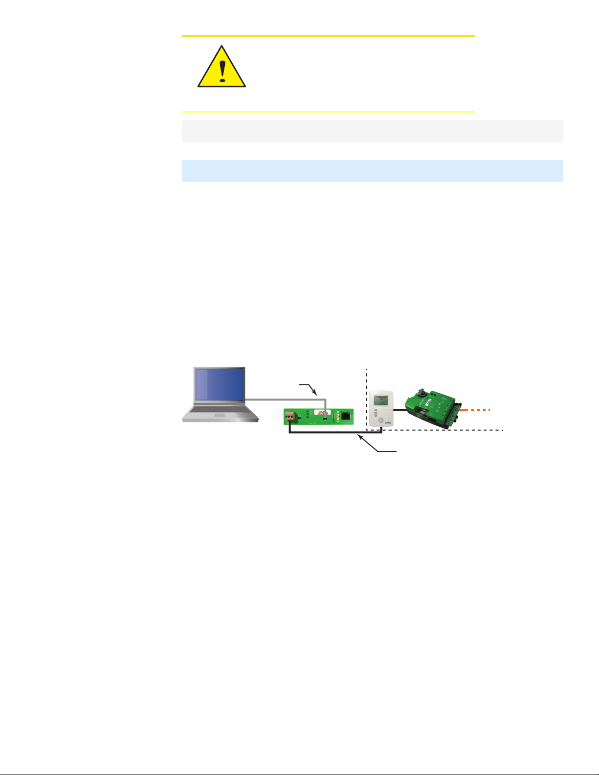
Using the router for a technician's service tool
To use the BAC-5051E router as a technicians service tool, connect it between a computer
running a service tool program and a BACnet internetwork. Use the following cables from the
HPO-5551 Router Technician's Cable kit to make the connections.
l The MS/TP to NetSensor cable
l The USB-A to USB-micro cable
Illustration 1–7 Router service tool connection
KMC Connect, TotalControl, BACstage, or other BACnet configuration program my be used
for the service tool program
Computer requirements The computer running the service or configuration program must
have a BACnet driver installed and configured to match a port in the service tool router. The
program also requires a unique Device Instance number assigned to the BACnet driver. The
exact details for setting up the driver vary with each program.
Router set up Using the router for service connection requires that the router is set up with a
unique device instance and network number between the computer and router. The network
between the computer and router may be one of the IPprotocols or the Ethernet protocol.
Typically, the normal IPprotocol is used when the router is connected between a computer
and an MS/TP network.
Revision J 13
l See the topic Setting up routing on page 27 for details on configuring the router's ports
for BACnet networks.
l Setting the device instance number is described in the topic Device properties page on
page 21.
Page 14

Section 1: Introduction KMC Controls, Inc.
To set up the router for a service connection, do the following:
1 Set up the computer and router fora single cable connection as described in the topic
Single-cable connection on page 11.
2 Connect the MS/TP to NetSensor cable between the router and the bottom of a
NetSensor or STE-6000 sensor with a network port.
3 Assign a unique device instance number and network number to the service tool
program.
4 Log in to the router with an HTML5 browser.
5 Assign a unique device instance number to the router.
6 Enable a port in the router for BACnet network.
l The protocol for the port, either IP or Ethernet, in the router must match the protocol
used by the service tool program.
l The BACnet network number assigned to the port must be unique on the BACnet
internetwork.
7 Enable the MS/TP port in the service tool router.
l Set the MS/TP network number in the router service tool to match the network
number that the devices on the building's network are using.
l Set the MS/TP MAC in the router that is unique on the MS/TP network.
l Set the baud rate to match the baud rate of the building's MS/TP network.
8 Start the service tool program. The BACnet devices on the internetwork will be
available for discovery. If it is a large internetwork, it may take a few minutes to
discover all devices.
14 Revision J
Page 15

BAC-5051E Router Section 2: Configuring the BAC-5051E router
Sec tion 2: Configuri ng the BA C-5051E r o u ter
This section provides important guidelines for configuring a router before it is placed on a
network. Review this information carefully for proper installation.
The router must be configured as a network device. To prevent disrupting an existing
network, configure the network address before connecting the router to the network. The
BACnet device instance and other properties can be configured at the same time or after the
router has an IPaddress assigned and it is installed in its permanent location on a network.
Topics in this section
Initial setup 15
Device properties page 21
Time page 22
Security page 24
Session timeout 26
Initial setup
Configure the BAC-5051E router with an HTML5 compatible web browser using the web
pages served from within the router. The router has the following default network address
values.
l IPaddress—192.168.1.252
l Subnet mask—255.255.255.0
l Gateway—192.168.1.1
You will need the following information before you can configure a router.
From the BACnet system engineer:
l BACnet device instance forthe router.
l Network numbers for each of the enabled networks.
l If applicable, the address and port for a PAD router or BBMD to which the router will
connect.
l A MAC address for the MS/TP port.
l The highest MAC address used on the MS/TP network.
l The baud rate for the MS/TP network.
From the IT system administer:
l The IP address for the router.
l The IP subnet mask for the Ethernet LAN to which the router will connect.
l The IP address of the network gateway.
Revision J 15
Page 16
USB for
power
Section 2: Configuring the BAC-5051E router KMC Controls, Inc.
l If the router is part ofa system that uses the Internet, you will also need the public IP
address and port.
You will also need an HTML5 compliant browser, Ethernet cable, and a USB-A to USB-B
micro cable or a 24 volt AC power source.
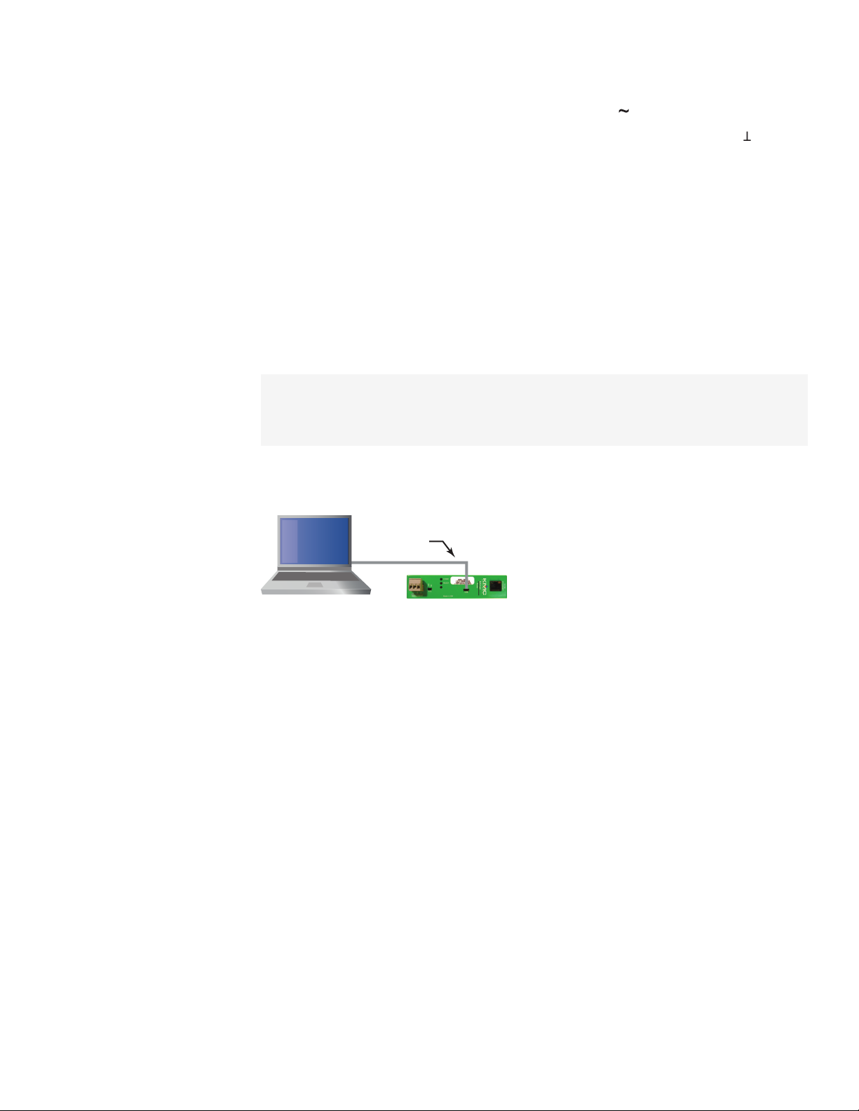
Set up for configuration
To configure the router, plug it into an Ethernet port. Typically this is a direct connection to a
computer Ethernet connection which requires changing the computer IPaddress. See the
procedure Changing your computer's address on page 18.
In addition to the Ethernet connection, supply temporary power to the router with a USB
cable. An alternative to the USB power connection is a 24 volt AC source. See Connecting
power on page 9.
Illustration 2–1 Connecting for configuration
Logging in
Use an HTML5 browser to log in and configure the router.
To log in, do the following.
1 Connect the router to an Ethernet port by doing one of the following.
l Connect directly to the computer.
l Connect to a subnet that recognizes address 192.168.1.252.
2 Connect the router to either USB or 24 volt AC power.
3 Open a new browser window.
16 Revision J
Page 17
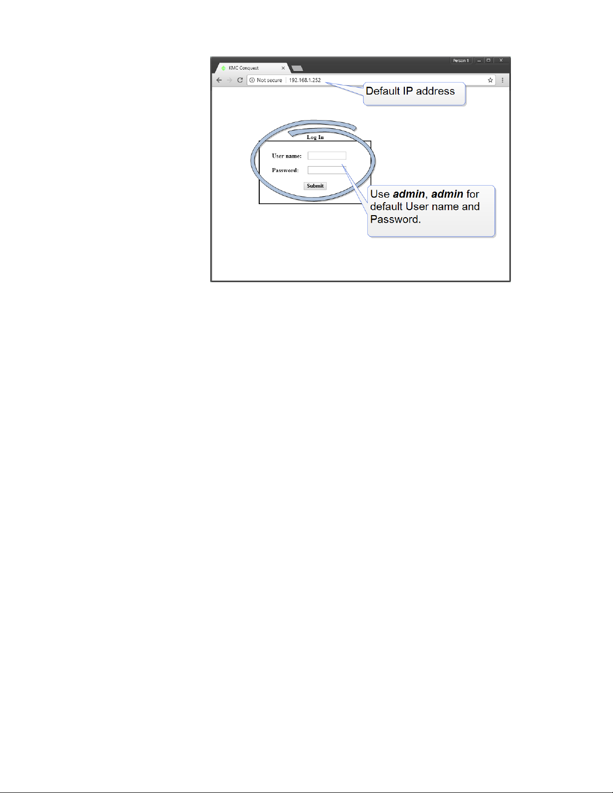
BAC-5051E Router Section 2: Configuring the BAC-5051E router
4 Enter the address 192.168.1.252.
5 At the log in window enter the following user name and password.
l User name: admin
l Password: admin
Revision J 17
Page 18
Section 2: Configuring the BAC-5051E router KMC Controls, Inc.
6 Once you have logged in, other parameters of the router can be changed from the
Home page.
l To change the IP address, see the topic Device properties page on page 21.
l To set up BACnet routing, see the topic Setting up routing on page 27.
l To change passwords and add users, see the topic Security page on page 24.
Note: Once you change the IP address, place the router on the new subnet and log in using the
new address. After the address is changed and saved, the router will not respond to the old
address.
Changing your computer's address
To directly connect a computer to a router, you must set the IPaddress of the computer to
be compatible with the IP address of the router.
1 From the Windows Control Panel, click Network and Internet and then Networking
Sharing Center.
18 Revision J
Page 19

BAC-5051E Router Section 2: Configuring the BAC-5051E router
2 Choose the local connection forthe LAN. Depending on the computer and version of
Windows, the exact name for the connection may be Ethernet, Local Area
Connection, or something similar.
3 In the Ethernet Status dialog, click Properties.
4 In the Ethernet Properties dialog, scroll and select Internet Protocol Version 4
(TCP/IP) and then click Properties.
Revision J 19
Page 20

Section 2: Configuring the BAC-5051E router KMC Controls, Inc.
5 In the Properties dialog, select Use the following IPaddress and then enter the
following for the IPaddress, subnet mask, and Gateway.
l IP address—192.168.1.10
l Subnet mask—255.255.255.0
l Gateway—Leave empty or unchanged
6 When all information is correct, click OK.
20 Revision J
Page 21

BAC-5051E Router Section 2: Configuring the BAC-5051E router
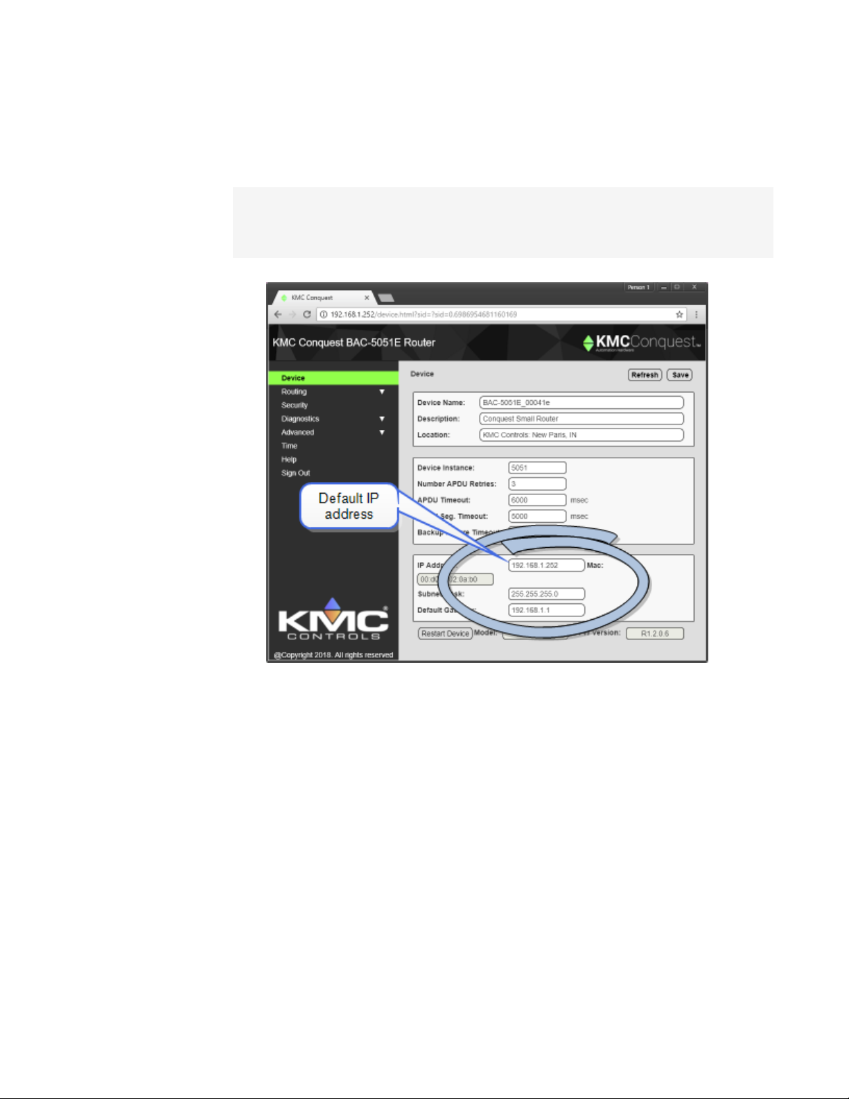
Device properties page
The Device page identifies the BAC-5051E router for the Local Area Network (LAN). The IP
Address, Subnet Mask, and Default Gateway values are supplied by the IT department
system administrator.
The Device page also identifies the router as a BACnet device and sets BACnet
communication properties. The default device instance for the router is 5051.
Note: Once the window is saved, the router will use the new settings and will require you to log in
at the new address. If the router is not on the same subnet as the network gateway router,
it will not function correctly.
Note: The Device Instance on this page identifies the BAC-5051E router as a BACnet device but
not KMD controllers as BACnet devices. See the topics Configuring the KMD Virtual Port
and KMD Subnet Device Configuration page.
Device Name The name must be unique among all devices on the BACnet internetwork.
Description Optional information not included in the device name.
Location An optional value that describes the router's physical location.
Device Instance A number that identifies the router on the internetwork. The device
instance must be unique on the internetwork and in the range from 0 to 4,194,302. The
device instance is assigned by the BACnet system designer. The default device instance is
5051.
Number APDU Retries Indicates the maximum number of retries that an APDU is
retransmitted.
Revision J 21
Page 22

Section 2: Configuring the BAC-5051E router KMC Controls, Inc.
APDU Timeout Indicates the time—in milliseconds—between retransmissions of an APDU
requiring an acknowledgment for which no acknowledgment has been received.
APDU Seg. Timeout The Segment Timeout property indicates the time—in milliseconds—
between the retransmission of an APDU segment.
Backup Failure Timeout The time—in seconds—that the router must wait before ending a
BACnet backup or restore procedure. Use a BACnet Operator Workstation such as KMC
Connect or TotalControl to backup the router.
IPAddress The internal or private network address of the router. For BACnet routing that
requires a public IPaddress, see Setting up routing on page 27.
Subnet Mask Mask determines which part of the IP address is used for a network identifier
and which part is used for a device identifier. The mask must match the mask for the
network gateway router and other devices on the subnet.
Default Gateway The address of the network gateway router. The BAC-5051E router and
gateway router must be part of the same LAN subnet.
Restart Device Restarts the router. Similar to restarting the router with a BACnet cold start
from KMC Connect or TotalControl. A restart does not change properties or save changes
not yet saved.
MAC The MAC (Media Access Control) address uniquely identifies the router on the local
area network. This number is assigned by the manufacturer and cannot be changed.
Time page
Set the properties of the Time page to set up the router as a BACnet time master device.
Time The local time and date as maintained by the router is displayed at the top of the web
page. Time and date can be entered directly or synchronized to the time in the computer
running the browser.
Sync to PC Click to immediately transfer the time and date maintained by the computer
running the browser to the router.
Refresh Clicking Refresh discards any changes and reloads router properties on the web
page.
22 Revision J
Page 23

BAC-5051E Router Section 2: Configuring the BAC-5051E router
Save When finished making changes, click Save to make the changes permanent.
BACnet Time Sync Networks
Selects the interval and type of BACnet time message foreach network.
Time Sync Period Sets the interval to send time synchronization to the selected BACnet
networks. The choices are None, Daily, Weekly, Monthly, or Custom. The Custom interval is
entered in minutes.
Interval Offset If Align Intervals is selected, the time synchronization messages are offset,
in minutes, from the beginning of the hour or day.
Align Intervals If selected and a Time Sync Period is specified, time synchronization
messages are sent at the start of the hour or day.
UTC Offset The UTC Offset property indicates the time offset—in minutes—between local
standard time and Universal Time Coordinated. The value of the property ranges from -780 to
+780 minutes. The time zones to the west of the zero degree meridian are positive values;
those to the east are negative values. The value of the UTC Offset property is derived from
the UTC received in a UTC Time Synchronization service request to calculate the correct
local standard time.
Sync Network Enabled networks are indicated with a green background. To enable a
network, see the topic Setting up routing on page 27.
Time Choice Sets the type of time synchronization to NONE, UTC, LOCAL, or UTC & LOCAL.
The router supports both UTC and local time synchronization.
l UTC The router sends time sync messages in Universal Time Coordinated (UTC). The
devices on the network then apply an offset to calculate local time and date. UTC is
the preferred method when the building automation system crosses time zones.
l Local time The router sends time sync messages in local time from which devices
update their internal clock.
Revision J 23
Page 24

Section 2: Configuring the BAC-5051E router KMC Controls, Inc.
Send Time To Recipients When clicked, the router immediately sends a BACnet time
service message to the designated networks.
SNTP Time Server
A Simple Network Time Protocol Server is a networkdevice that synchronizes the time for
devices connected to a local area network. The router receives these time messages and
rebroadcasts them as BACnet time service messages.
IP Address Enter the address of the SNTP server. The address is supplied by the IT
department.
Sync Period Select an hourly, daily, weekly, monthly, or a custom interval to send the time
synchronization message. The custom period is set in minutes.
Test Server Click to test the connection to the network SNTP server.
Daylight Saving Time
DST Status This property indicates ACTIVE when Daylight Saving Time is in effect and
INACTIVE when it is not in effect.
DST Enable Enables the router to change its time to Daylight Saving Time. The period of
Daylight Saving Time is defined by DST Start Time and DST End.
DST Auto Calculation Selecting this check box sets the type of Daylight Saving Time
calculation. When selected, the router uses a rules-based calculation for DST based on the
day of the month in DST Start Time and DST End Time. When this check box is clear, DST is
set to specific calender dates.
DST Start Time Enter the day and time that starts Daylight Saving Time.
DST End Time Enter the day and time that ends Daylight Saving Time.
Security page
The Security page sets user access to the router. Assign users to one of the five access
levels.
l The user name list must include at least one name with Administrator privileges.
l User names and passwords are case sensitive.
l Only the Custom access level can be changed.
24 Revision J
Page 25

BAC-5051E Router Section 2: Configuring the BAC-5051E router
The router is configured with the following default user name and password.
l User name: admin
l Password: admin
Table 2–1 Security access levels
Configure Diagnostic Security Balancing
Administrator Display
Modify
Display
Modify
Display
Modify
Display
Modify
View Only Display Display
Operator Display
Modify
Display
Modify
Balancing Display
Modify
Custom Display*
Modify*
Display*
Modify*
Display*
Modify*
Display*
Modify*
*Assigned as required.
Revision J 25
Page 26

Section 2: Configuring the BAC-5051E router KMC Controls, Inc.
Session timeout
The browser session will automatically close after one hour of inactivity. After 58 minutes,
the Reset Session Timer button appears on any open page. Click to reset the session timer.
26 Revision J
Page 27

BAC-5051E Router Section 3: Setting up routing
Sec tion 3: Setti n g u p r o u ting
This section provides important guidelines for configuring a KMC BAC-5051E router for
BACnet routing. Review this information carefully for proper installation.
The BAC-5051E supports the following routing protocols.
l One MS/TP network
l One BACnet Ethernet
l Two IP networks that can be set up for any of the following protocols:
l Normal BACnet IP network routing
l BACnet broadcast management device with network and port address translation
l Foreign device registration with BACnet broadcast management devices (BBMD)
l PAD (packet assembling/disassembling) routing
Setting up routing can be performed either during initial configuration or after the router has
an IPaddress assigned and is installed in its permanent location. See Configuring the BAC-
5051E router on page 15 for initial configuration and log in procedures.
Topics in this section
BACnet IP routing 27
BACnet foreign device routing 28
BACnet Broadcast Management Device routing 30
BACnet PAD routing 32
BACnet Ethernet routing 33
MS/TP configuration 34
Router Core properties page 35
BACnet IP routing
Either of the two IP ports can be configured for normal IProuting. The values on this page
are assigned by the BACnet system engineer.
For the log in procedure, see the topic Initial setup on page 15.
1 Use an Internet browser to log in.
2 Click Routing and then Configuration.
3 Select Enable for one of the IP Ports.
4 Select Enable for the IP Port.
5 From the list box, choose IP (Normal).
Revision J 27
Page 28

Section 3: Setting up routing KMC Controls, Inc.
6 Set the Network and Port properties as needed and then click Save.
Note: The router will restart when changes are made. For additional changes, log in
again.
Enable Select to enable the network. The port block turns green when enabled.
Port Assign a unique UDP port number to each of the enabled IP networks. The default port
number is 47808.
Net Designates the BACnet network number for the port. Assign network numbers in the
range from 1 to 65534.
Other IProuting protocols
l BACnet Broadcast Management Device routing on page 30
l BACnet PAD routing on page 32
l BACnet foreign device routing on page 28
l Router Core properties page on page 35
BACnet foreign device routing
Either of the two IP ports can be configured as a BACnet Foreign device. The values on this
page are assigned by the BACnet system engineer.
For the log in procedure, see the topic Initial setup on page 15.
1 Use an Internet browser to log in.
2 Click Routing and then Configuration.
3 Select Enable for the port.
4 From the list box, choose Foreign Device.
28 Revision J
Page 29

BAC-5051E Router Section 3: Setting up routing
5 Set other properties as needed and then click Save.
Note: The router will restart. Foradditional changes, log in again.
Enable Select to enable the network. The port block turns green when enabled.
Net Designates the BACnet network number for the port. Assign network numbers in the
range from 1 to 65534.
Port Assign a unique UDP port number to each of the enabled IP networks. The default port
number is 47808.
Remote IP Enter the address of the remote BBMD. If network address translation (NAT) is
used between the BAC-5051E router and the BBMD, contact the network system
administrator for the correct public IP address.
Remote Port Enter the port number of the remote BBMD. If port address translation (PAT) is
used between the BAC-5051E router and the BBMD, contact the network system
administrator for the correct public UDP port.
Time To Live Sets the interval at which the router sends a registration message to the
BBMD with which it is registered. The valid time range is 1-65535 seconds.
If the BBMD does not receive a registration message within the value of the period set by
Time To Live plus 30 seconds, the BBMD will remove the router from its foreign device table
and will not send broadcast messages to the router.
Other IProuting protocols
l BACnet IP routing on page 27
l BACnet Broadcast Management Device routing on page 30
l BACnet PAD routing on page 32
l Router Core properties page on page 35
Revision J 29
Page 30

Section 3: Setting up routing KMC Controls, Inc.
BACnet Broadcast Management Device routing
Either of the two IP ports can be configured as a BACnet Broadcast Management Device
(BBMD). When configuring an IP port as a BBMD, keep in mind the following rules.
l Configure only one BBMD for a single IP subnetwork.
l Assign the same BACnet network number to all BBMDs on the internetwork.
l The BBMD can accept registration from foreign devices or perform BBMD-to-BBMD
routing.
For the log in procedure, see the topic Initial setup on page 15.
To set up the router as a BBMD, do the following:
1 Use an Internet browser to log in.
2 Click Routing and then Configuration.
3 Select Enable for the port.
4 From the port list box, choose BBMD.
5 Click Table and then add entries to the Broadcast Distribution Table (BDT).
6 Set other properties as needed and then click Save.
Note: The router will restart. Foradditional changes, log in again.
Enable Select to enable the network. The port block turns green when enabled.
Net Designates the BACnet network number for the port. Assign network numbers in the
range from 1 to 65534.
Port Assign a unique UDP port number to each of the enabled IP networks. The default port
number is 47808.
30 Revision J
Page 31

BAC-5051E Router Section 3: Setting up routing
Network address translation
When using Network address translation, coordinate with the IT department to obtain a
public IPaddress and a port exception in the firewall.
Use public address Select to enable network address translation and port forwarding.
Public address The static public IP address supplied by the IT department.
Public port The public UDP port supplied by the IT department. For security, use a port that
is not in the typical range of BACnet ports.
Table
The items in Table define the Broadcast Distribution Table (BDT) for the BBMD. Enter an IP
address, UDP port number, and IP subnet mask of each BBMD that is part of the
internetwork.
l If none of the BBMDs are using a public IP address, the BDT entries in every BBMD are
the same.
l If the BBMD uses a public IPaddress, the BDTs are different in every router. Each BDT
will use its own private IPaddress, port number, and subnet mask and the public
IPaddress, port number, and subnet mask for all of the other BBMDs on the
internetwork.
To add or delete entries, do the following:
l Adding entries—Click Add for additional entries.
l Deleting entries—Select sel and click Delete.
Max FDT Table Entries Sets the maximum number offoreign devices that can register at
one time. The value for MAX FDT Entries is 1–128.
Enable FD Service When selected, the BBMD permits foreign devices to register with the
BBMD. The maximum number of devices is limited by the value in Max FDT Table Entries.
Accept Remote Configuration When selected, the BBMD will update the BDT with a table it
receives from another BBMD.
Other IProuting protocols
l BACnet IP routing on page 27
l BACnet PAD routing on page 32
l BACnet foreign device routing on page 28
l Router Core properties page on page 35
Revision J 31
Page 32

Section 3: Setting up routing KMC Controls, Inc.
BACnet PAD routing
Either of the two IP ports can be configured for PAD (Packet Assembling and
Dissassembling) routing to a companion PAD router located on a different subnet. The
values on this page are assigned by the BACnet system engineer.
For the log in procedure, see the topic Initial setup on page 15.
1 Use an Internet browser to log in.
2 Click Routing and then Configuration.
3 Select Enable for the port.
4 From the list box, choose PAD.
5 Set other properties as needed and then click Save.
Note: The router will restart. Foradditional changes, log in again.
A BACnet IP PAD router is a special type of router that connects two or more BACnet network
segments that are separated by at least one IP-only router. The PAD router monitors network
traffic for BACnet messages addressed to other subnets and then repackages the message
so that they can pass through IP routers, in effect forming a “tunnel” between the two
network segments. A companion PAD router unpacks and retransmits the message on the
remote BACnet network.
Enable Select to enable the network. The port block turns green when enabled.
Net Designates the BACnet network number for the port. Assign network numbers in the
range from 1 to 65534.
Port Assign a unique UDP port number to each of the enabled IP networks. The default port
number is 47808.
Remote IP Enter the address of the remote PAD router. If network address translation (NAT)
is used between the local router and the PAD router, contact the network system
administrator for the correct public IP address.
32 Revision J
Page 33

BAC-5051E Router Section 3: Setting up routing
Remote Port Enter the port number of the remote PAD router. If port address translation
(PAT) is used between the BAC-5051E router and the PAD or BBMD, contact the network
system administrator for the correct public IP address.
Other IProuting protocols
l BACnet Broadcast Management Device routing on page 30
l BACnet IP routing on page 27
l BACnet foreign device routing on page 28
l Router Core properties page on page 35
BACnet Ethernet routing
Configure the Ethernet port in this page. The values on this page are assigned by the BACnet
system engineer.
For the log in procedure, see the topic Initial setup on page 15.
1 Use an Internet browser to log in.
2 Click Routing and then Configuration.
3 Select Enable for the Ethernet port.
4 Enter the Network number and then click Save.
Note: The router will restart. Foradditional changes, log in again.
Enable Select to enable the network. The port block turns green when enabled.
Net Designates the BACnet network number for the port. Assign network numbers in the
range from 1 to 65534.
Revision J 33
Page 34

Section 3: Setting up routing KMC Controls, Inc.
MS/TP configuration
Configure the MS/TP network in this page. The values on this page are assigned by the
BACnet system engineer.
For the log in procedure, see the topic Initial setup on page 15.
1 Use an Internet browser to log in.
2 Click Routing and then Configuration.
3 Select Enable for the MS/TP port.
4 Enter the Network number and a MAC address for the router.
5 Set Baud Rate. All devices on the MS/TP network must use the same Baud.
6 When finished, click Save.
Note: The router will restart. Foradditional changes, log in again.
Enable Select to enable the network. The port block turns green when enabled.
Net Designates the BACnet network number for the MS/TP port. Assign a network number
that is in the range from 1-65534.
Baud Rate Select the baud rate from the drop down list. The Baud Rate for the router and all
devices connected to the MS/TP networkmust use the same rate.
34 Revision J
Page 35

Caution
BAC-5051E Router Section 3: Setting up routing
Max Master Set to 127 or no lower than the highest MAC address on the network. See
Device Status page on page 42.
Usage Timeout Sets the maximum time the router will wait on a response from a master
device before passing the token. The default value is 20 milliseconds.
MAC Address The MAC (Media Access Control) address assigned to the router for the
MS/TP network. This must be unique on the MS/TP network and in the range from 0–127.
Typically the MAC address fora router is zero (0).
Router Core properties page
The Router Core properties are general properties that apply to all routing protocols. The
properties consist of the Home Port selection and the Routing properties.
Home Port
Because the router is a BACnet device, it must be connected to one of the BACnet networks
by setting the Home Port property.
The home port is designated on a router port by the Home Port icon .
l
l The home port sets the network on which the router is connected. In operator
workstations, the router appears on the network designated as the home port network.
l The home port can be assigned only to an enabled network.
Using the MS/TP network reduces the APDU size and
significantly increases network traffic. KMCControls
recommends that one of the IP ports or the Ethernet port is
designated as the home port.
Illustration 3–1 Router Home Port
Revision J 35
Page 36

Section 3: Setting up routing KMC Controls, Inc.
Routing properties
Route On Startup When selected, the router will immediately begin routing after a power
cycle or BACnet Cold start. This includes restarting the router on the Device properties page
on page 21. The router will also select the Enable Routing check box during the reset or
power up procedure.
Enable Routing When this check box is clear, routing on all ports is disabled but the router
remains an active device on the BACnet Internetwork. The MS/TP diagnostic and Routing
Status pages are still active. When routing is not enabled the background of Router Core is
gray. When routing is enabled the background is green. Routing can also be enabled or
disabled on the Routing Statuspage on page 37.
Use Learned Networks When selected, the router will attempt to learn the network number
being used on a port. This only works if there is at least one other router on the network that
responds to a BACnet What-Is-My-Network-Number message. If available the router
will use the learned network otherwise the router will use the configured network number.
Illustration 3–2 Routing properties
36 Revision J
Page 37

BAC-5051E Router Section 4: Diagnostics and status
Sec tion 4: Diagnostics an d s tatus
Topics in this section cover the diagnostic and status functions of the BAC-5051E router.
The BAC-5051E router includes several status and function pages for diagnosing problems
and improving the efficiency of the connected networks.
l The topic Routing Statuspage applies to all connected networks.
l The topics Device Status page, MS/TP Metrics page, and Token Use page apply to the
MS/TP network.
Topics in this section
Routing Status page 37
Device Status page 42
Token Use page 44
MS/TP Metrics page 46
MS/TP Capture page 49
Routing Status page
The Routing Status page contains a network status list and command buttons to update the
display and networks. The page consists of three major parts.
l Send commands to the router with the Route Status buttons on page 38.
l View the status of networks in the Route Status list on page 39.
l Clear selected networks by Purging the Route Status list on page 41.
Enable Routing When this check box is clear, routing on all ports is disabled but the router
remains an active device on the BACnet internetwork. The MS/TP diagnostic and Routing
Status pages are still active. Routing can also be enabled or disabled on the Router Core
properties page on page 35.
Note: Enable Routing will not remain selected after a restart if Route On Startup is not selected on
the Router Core properties page on page 35.
Revision J 37
Page 38

Section 4: Diagnostics and status KMC Controls, Inc.
Refresh Click to refresh the Route Status list. To automatically refresh the list every 10
seconds, select the Auto Refresh check box.
Illustration 4–1 Routing Status page
Route Status buttons
The Route Status buttons are useful for diagnosing routing and network problems.
Send I-Am-Router-To-Network Broadcasts to all networks that the router is on the network.
This can trigger internetwork wide updates.
Clear Direct Network Status Forces the status of all direct networks to Active. If a network
problem continues after clearing the direct networks, the networks with problems will return
to a status other than Active.
Purge Remote Networks Removes all remote routes from the network table.
Send Who-Is-Router-to-Network Initiates a query to other routers that results in the
discovery of other networks. Other routers respond with a BACnet I-Am-Router-To-Network
message.
Clear Remote Networks Forces the status of all remote networks to Active. If a problem
continues with a remote network, it will return to a status other than Active.
Send Sequence Sequentially broadcasts the three commands Purge, Clear, and Send I-Am-
Router-To-Network.
38 Revision J
Page 39

BAC-5051E Router Section 4: Diagnostics and status
Route Status list
The Routing Status list is a diagnostic display of all networks known to the router. Both direct
and remote networks are listed.
l Direct (or local) networks are connected directly to the router.
l Remote networks are on the other side of one or more remote routers. The path to a
remote network always includes at least one directly connected network.
Each of the columns lists information about local or remote networks.
Tip: If a directly connected network is shown to have a problem, the remote networks that
connect to it will also show problems. Correct directly connected network problems before
troubleshooting remote network problems.
Status The status of each network known to the router. See the table Route status
conditions for a description of each condition.
Net The columns under Net will change modes depending on the setting of Use Learned
Networks on the Routing Status page on page 37.
Destination The Destination is always the network number the router is using.
l If Use Learned Networks is enabled, this is the learned network number.
l If Use Learned Networks is not enabled, this is the network number entered for
the port on the Configuration page.
Configured (Use Learned Networks enabled) The network number that is configured
for the port on the Configuration page. If this number is different than the Destination
network, the networknumber is in red.
Discovered (Use Learned Networks not enabled) The learned network number at a
port. If this network number is different than the network number on the Configuration
page the number is in red and the status will be other than Active. Other networks are
listed as N/A.
Next Router A list of each network connected to the router's ports that will be used to route
a message to the next router.
l Network The BACet network number to the next router.
l Address The MAC address of the next router.
Time The elapsed time since the status update.
Idle Time The elapsed time since the last traffic was passed to the networkby the router.
Revision J 39
Page 40

!
D
M
S
Section 4: Diagnostics and status KMC Controls, Inc.
Table 4–1 Route status conditions
Status Icon Description Action
Active The network is
functioning correctly and
capable of passing
traffic.
Busy The amount of network
traffic is high enough
that no new traffic can
be accepted.
Down
Gone
No Status
Duplicated Network
The network is not
functional and is
rejecting traffic.
The router is searching
for the network.
Two networks are using
the same network
number. A router cannot
pass traffic on a
duplicated network.
None required.
A temporary condition
that does not require
intervention.
Most likely will require
manual intervention.
Conditions that cause
a networkto be down
may include either LAN
or BACnet router
problems.
Usually a temporary
condition. Does not
require intervention.
Usually requires
intervention to locate
and change the
duplicated network
number. Multiple
duplicated networks
are usually an
indication of a network
loop.
Duplicate MAC
Sole Master
40 Revision J
The router has detected
two MS/TP device using
the same MAC address.
Traffic is not routed.
The router is not
detecting any master
MS/TP devices on the
local network. Slave
devices however, may
be present.
Change the MST/TP
MAC address in either
the router or the device
that contains the
duplicated number.
Requires corrective
action if master
devices are known to
be connected to the
local MS/TP network.
Page 41

B
B
F
BAC-5051E Router Section 4: Diagnostics and status
Table 4–1 Route status conditions (continued)
Status Icon Description Action
BBMD: Unknown
BBMD: Multiple
Foreign Device NAK
Indicates the router is
receiving BBMD traffic
from an unknown BBMD.
This does not stop traffic
from routing.
Indicates the router has
detected another BBMD
in the same subnet as
itself. Traffic is not
routed.
A foreign device is
preventing the router's
request to distribute
messages. Initially, this
will not block traffic.
However, as additional
registration requests are
received, attempts
speed up until traffic is
stopped.
If appropriate, add the
unknown BBMD to the
local BDT. A possible
cause of unknown
traffic is an address
issue because of
network address
translation.
Remove a BBMD from
the network.
The remote device
server cannot register
additional devices.
Increase the value of
Max FDT Entries in the
remote server or
register with a different
server.
Mismatched Network
Number
The learned network
does not match the
configured network.
Select Use Learned
Networks on the
Configuration page or
change the router's
network number.
Purging the Route Status list
To clear old data from the Route list, select a network and then click Purge.
l Choose Select to remove a specific remote network from the table.
l Choose Select Routes to remove all of the remote routes related to a directly
connected network.
The selected network or networks are then cleared from the list. As the router detects the
actual networks in use, they are added back to the list.
Revision J 41
Page 42

Section 4: Diagnostics and status KMC Controls, Inc.
Device Status page
The Diagnostics Status page is a color coded status display and a list of metrics for the
MS/TP network. Background color indicates the status of each MAC address.
Note: When the Diagnostics page opens, the router shows active network devices in green. After
clicking Refresh, any device that was active but has stopped communicating within the last
few seconds changes from green to gray.
See the topic Setting up routing on page 27
Refresh Updates the window with the latest network status.
Clear Deletes all current values in the MS/TP Status display and Metrics list.
Table 4–2 Device status
Color Icon Description
White No device is assigned to this MAC address.
Gray A device was active with this MAC address but is no longer online.
Blue The MAC address assigned to the router.
Green The MAC address is assigned to an active device.
Red Two devices are using the same MAC address.
42 Revision J
Page 43

BAC-5051E Router Section 4: Diagnostics and status
If you encounter difficulty, click Refresh about every ten seconds to see how the Device
Status changes.
l If a MAC is red, start disconnecting devices from the networkand click Refresh as you
disconnect until the red goes away. This will help find the device that has the same
MAC address as the router.
l Gaps in the MAC addresses. MAC address gaps make the network less efficient
because devices will continually search for devices in the gap. Small gaps between
the router and the first device is okay, but you should try to eliminate gaps between
devices by changing MAC addresses.
l Gray can indicate several issues. This means communications at or near the gray
MAC address is intermittent. This can be caused by noise, loose wiring, and duplicate
MAC addresses. It could mean the end-of-line termination is not set properly. It could
mean a device has bad power and is resetting often. The problem is usually
associated with the first device that is shown gray.
l Known devices are not green. This is usually caused by bad wiring, bad grounding, or
not having the same baud-rate for the router and devices. To isolate the problem, start
splitting the network by physically disconnecting wires until devices begin
communicating.
The network metrics are useful for evaluating overall networkperformance.
Network metrics
Metric Description
Total Devices Number of devices on the network including the
router
AVG Token Cycle time The time for the token pass to all controllers and
return.
AVG Token Time per device Typically 10 ms or less.
Last Master MAC Address The highest MAC found by the router.
Revision J 43
Page 44

Section 4: Diagnostics and status KMC Controls, Inc.
Token Use page
The Token Use page is a dynamic display of token passing on the network. The colors of
each device indicate the speed of token passing.
Illustration 4–2 MS/TP Token Use page
Token use by color
Color Description Condition Action
Blue The MAC address assigned to
the router.
Light traffic.
Will change to green or yellow
None required.
if traffic increases.
Green Token passed in less than 100
Normal token passing. None required.
ms.
Yellow Token passed in more than 100
ms but less than the value of
APDU Timeout.
Red APDU Timeout The device is retaining the
Token passing is slow but the
device is still functional.
token too long.
Indicates a potential
bottleneck. No action if device
returns to green.
A bottleneck in network
traffic. Typical cause is
excessive or continuous
polling for data in other
controllers.
Light Blue Poll for Master A device is polling for a
master device.
This is normal if there are
gaps in the MAC addresses.
44 Revision J
Page 45

BAC-5051E Router Section 4: Diagnostics and status
Stop when full When selected full Stop when full freezes the capture when the frame buffer
is full.
Clear Removes data from the window and refreshes it with the current network status.
The network metrics are useful for evaluating overall networkperformance.
Network metrics
Metric Description
Total Devices Number of devices on the network including the
router
AVG Token Cycle time The time for the token pass to all controllers and
return.
AVG Token Time per device Typically 10 ms or less.
Last Master MAC Address The highest MAC found by the router.
Revision J 45
Page 46

Section 4: Diagnostics and status KMC Controls, Inc.
MS/TP Metrics page
The network metrics are useful for evaluating network performance and troubleshooting.
Illustration 4–3 Diagnostic metrics
Interpreting the diagnostic data
Even the best designed and installed network will have minor or infrequent communications
issues. The following tips will help determine the significance of the networkmetric as well
as suggestions forimprovement.
Tx and Rx Frame Counts The actual number of frame counts depends on the baud rate and
number of network devices. The more connected devices, the slower the frame counts
grow. Unless the relative difference between the two counts is greater than 10%, the network
is generally okay. The reason is the router sends more messages than it receives is primarily
because of the small gap between its own MAC address and the next device.
46 Revision J
Page 47

BAC-5051E Router Section 4: Diagnostics and status
Rx Frame Count greater than Tx Frame Count The greater the difference, the higher the
probability of the following conditions.
l One or more devices somewhere in BACnet internetwork is sending a lot of broadcast
messages.
l One or more devices on the router’s MS/TP network is sending a lot of network unicast
messages.
Typically a device is trying to find other devices that do not exist or are not communicating
properly and are repeatedly sending BACnet WHO-IS messages. Usually this is caused by a
Control Basic program or a Notification Class object recipient list referring to a device that
does not exist.
Rx Frame Count much less than Tx Count Will probably also see a device in a gray offline
status. It usually means devices are not communicating reliably either because of noise or
they because they are inundated with network messages and cannot keep up.
Tx Data Count This is the number of messages that contain actual point data. Most other
messages are just passing the token. In the previous example, the Data Count is only 0.1%
of the Tx Frame Count which just means the network is passing a small number of points or
trends. If this ratio is more than 30%, it may indicate a problem because it is likely that one or
more devices or workstation are gathering more data than is really needed. This can mean
the network will drop important messages.
Token Retry or Token Timeout This usually indicates a problem with the device next to the
router in the MAC chain. The cause could be noise specific to the device or general network
noise. This is not a problem unless this count is more than ten counts in a 24-hour period.
Rx PFM Count This indicates a problem between the router and the device just before it in
the MAC chain, usually the one at the end. A few counts in a 24-hour period is not unusual.
All other metrics Other metrics typically do not indicate a problem unless a value exceeds
ten counts in a 24-hour period. If you encounter issues, see the topic If you encounter
difficulty on page 12 to contact technical support.
Revision J 47
Page 48

Section 4: Diagnostics and status KMC Controls, Inc.
Description of the Metrics page
The following table describe each of the properties displayed on the MS/TP Metrics page.
Table 4–3 Diagnostic metrics
Metric Description
TX Frame Count The number of transmissions sent by the router.
Tx Data Count The number of transmissions sent by the router
that included data.
Tx ErrorCount The number of transmissions sent by the router
that were in error.
Rx Frame Count The number of frames received by the router.
Rx CRC Error Count The number of frames intended for the route with
a bad CRC (Cyclic Redundancy Check).
Rx Unexpected Frame Count The number of frames with an unexpected error
that were received by the router.
Duplicate MAC Count The number of times the router received a
message from another device with the same
MAC.
Token Retry Count The number of times the router had to retry
passing the token.
Token Timeout Count Number oftimes the token passing from the
router to the next device failed.
RX Token Count Number of times the router received the token.
RX PFM Count Number oftimes the router saw a poll-for-master
message for its own MAC.
PFM Error Count The number of times the router was expecting a
poll-for-master message and did not receive it.
RX Frame Abort Count The number of frames that were terminated
because of a timeout error.
RX Discard Count The number of frames rejected because of
mismatched timing or preambles.
RX FB Reparse Count The number of times more than one frame was
found inside of the frame buffer.
48 Revision J
Page 49

BAC-5051E Router Section 4: Diagnostics and status
MS/TP Capture page
Use the MS/TP Capture page to monitorand save the BACnet traffic on the MS/TP network.
The captured traffic can then be saved in a standard .pcap (Packet CAPture) file format.
Once saved, analyze the data with Wireshark or any other network analyzing program that
uses .pcap files. The router must be connected directly to the monitored MS/TP network.
This can be from either an existing router or a router temporarily connected as a service tool.
Illustration 4–4 MS/TP Capture page
Current State Shows the status of the capture. The status can be any of the following
conditions.
l Idle
l Starting Capture
l Capturing
l Ending Capture
l Data Ready
l Error
Start Now Select this check box and then click Save to start a capture. The capture will
continue until the length of time set in Max Time, the amount of data set in Max Length, or
the maximum buffer size is reached.
Stop Now Select this check box and then click Save to end a capture. The data can then be
saved by clicking Download Capture.
Revision J 49
Page 50

Section 4: Diagnostics and status KMC Controls, Inc.
Start on Restart Select this check box and then click Save. The router will restart and
capture MS/TP traffic until the Max Time or Max Length is reached or the buffer is full. The
maximum amount of space to store captured data is 1 gigabyte. The router will capture
MS/TP traffic after every restart until Start on Restart is cleared.
Max Time Enter the length of time, in seconds, for a timed capture.
Max Length The amount of data, in bytes, to capture.
Last Start Time For information only. This is the time—as maintained by the clock in the
router—when the last capture started.
Last End Time For information only. This is the time—as maintained by the clock in the
router—when the last capture ended.
Capture Filled The percentage of available buffer space to store a capture. The maximum
amount of space to store captured data is 1 gigabyte.
Download Capture When this link is blue, captured data is ready to save to the computer on
which the browser is ruining. Data is saved in the file format .pcap (Packet CAPture). The
first capture is saved as Capture.pcap. Additional captures are saved with a number
added to the file name (Capture(1).pcap, Capture(2).pcap, etc.). Files are
saved in the downloads folder forthe current Windows user.
50 Revision J
Page 51

BAC-5051E Router Section 5: Advanced features
Sec tion 5: Adv an c ed f eatures
This section covers features for updating and backing up the BAC-5051E router.
Features in the Advanced group are for updating the firmware and backing up the router
configuration.
Recovering the IPaddress Discover an unknown networkIP address.
Firmware updates—From time to time, KMC Controls issues updates to the firmware forthe
router. The updates can be added directly to the router from the browser pages.
Configure from file—Configuration properties for the router can be saved in a JSON
(JavaScript Object Notation) file. The file can then be used as a backup file or to configure
other routers with similar properties.
Topics in this section
Recovering the network address 51
Updating the firmware 53
Configure from a file 54
VAV balancing and configuration 55
Recovering the network address
If the network address of the router is lost or unknown, the router will respond to the default
IPaddress for the first 20 seconds after power is applied.
1 Disconnect the router from the LAN and connect the router as described in the topic
Initial setup on page 15.
2 Unplug the router from the power source.
3 On the computer, open a browser window and enter the default address of
192.168.1.252.
4 Reconnect the router from the power source and immediately attempt to connect with
the browser. The browser will respond with the router's IP address and subnet mask.
Revision J 51
Page 52

Section 5: Advanced features KMC Controls, Inc.
5 Once the address is known, connect the router to the correct IPsubnet for normal
operation orrouter configuration.
52 Revision J
Page 53

BAC-5051E Router Section 5: Advanced features
Updating the firmware
The router firmware can be updated from the Firmware page in the Advanced group.
Note: The router firmware can also be updated with KMC Connect, TotalControl, or the Firmware
Upgrade Tool. For instructions, see the help and other documentation for those programs.
Illustration 5–1 Firmware update page
To update the firmware, do the following:
1 Download the new firmware from the KMC partner portal. The file is a self extracting
executable file that will install the firmware in the correct location.
2 Run the downloaded file. This will place a .zip file in the folder at
C:\ProgramData\KMC Controls\Firmware Upgrade
Manager\BACnet Family\BAC-5051E. Do not unzip this file.
3 Use an Internet browser to log in to the router.
4 From the Advanced group, choose Firmware.
5 Click Choose File and browse to the following location: C:\ProgramData\KMC
Controls\Firmware Upgrade Manager\BACnet Family\BAC5051E.
6 Locate and open the folder with the correct version of firmware and then select the
.zip file.
7 When the Proceed with Download dialog opens, click OK.
8 When the download is finished, click Commit. The router will restart.
Revision J 53
Page 54

Section 5: Advanced features KMC Controls, Inc.
Configure from a file
Configuration properties for the BAC-5051E router can be saved in a configuration file. The
configuration file can then be used as a backup file or to configure other routers with similar
properties.
1 Use an Internet browser to log in.
2 From the Advanced group, click Choose File.
3 Browse to the file location, choose the file, and then click Open.
4 When the Overwrite Router Configuration dialog opens, click OK to precede.
Choose File Browse to the location and choose the configuration file.
Save Configuration Saves the router configuration in the file config_5051E.json.
The file type is JSON (Java Script Object Notation) and it is saved in the Windows current
user's downloads folder.
Illustration 5–2 Configure from File page
54 Revision J
Page 55

BAC-5051E Router Section 5: Advanced features
VAV balancing and configuration
Topics in this section are forcontrol technicians or engineers who will be balancing the
airflow in BAC-8000 or BAC-9000 series controllers. The BAC-5051E includes the following
features for balancing, configuring, and commanding airflow in a VAV controller.
l VAV balancing on page 55
l Configuring VAV setpoints on page 56
l Commanding and monitoring airflow on page 57
VAV balancing
The airflow balancing procedure described in this topic requires the following items.
l A flow hood or other accurate method to measure airflow.
l The engineering design specifications forthe minimum and maximum airflow
setpoints.
l A user name and password with permission to the VAV balancing feature in the
BAC-5051E.
Note: If the VAV unit is a heat only or cooling only unit, the airflow setpoints for the unused mode
must be set within the range of the mode in use. Failure to set the unused setpoints
correctly will result in unpredictable or erroneous air balancing settings.
Note: Starting the balancing procedure erases all previous airflow correction factors. The airflow
readings displayed on the VAV balancing page are the actual uncorrected airflow readings
as measured by the controller
1 Use an Internet browser to log in.
2 From the Advanced group click Balancing.
3 Enter a range of device instance values for the VAV units to be balanced.
4 Click Discover. Up to 50 devices will be added to the list.
5 Select a VAV unit from list of discovered units. The background of the selected unit
changes to yellow.
6 At the bottom of the page click the Balance tab.
7 Click Start Balancing. The controller commands the VAV controller to position the
damper for maximum airflow.
8 Wait forthe Actual Airflow value to stabilize.
9 With a flow hood, measure and note the actual airflow.
10 Enter the measured airflow in the Measured Max textbox. The controller then
commands the VAV controller to position the damper forminimum airflow.
11 Again, wait for the Actual Airflow value to stabilize.
12 With a flow hood, measure and note the actual airflow.
Revision J 55
Page 56

Section 5: Advanced features KMC Controls, Inc.
13 Enter the measured airflow in the Measured Min textbox. The program in the controller
calculates new airflow constants and returns the VAV controller to normal operation.
Note: Fordual-duct VAV systems, both the primary and secondary airflows are displayed by the
application.
Configuring VAV setpoints
Airflow setpoints in BAC-8000 or BAC-9000 series controllers can be change from the
Configure tab.
1 Log in and discover the VAV units as described in the steps 1-5 in VAV balancing.
2 At the bottom of the page click the Configure tab.
The values shown are the actual values in the controllers. The values forDual
Minimum Flow and Secondary K Factor are active only if a dual-duct VAV controller is
selected.
56 Revision J
Page 57

BAC-5051E Router Section 5: Advanced features
3 Make changes as needed and click Save when finished.
Commanding and monitoring airflow
Command the airflow to a specific level to make adjustments or measurements that require
a steady airflow.
1 Log in and discover the VAV units as described in the steps 1-5 in VAV balancing.
2 At the bottom of the page click the Command tab.
3 Enter an airflow or damper position value.
4 Click Start Commanding.
5 When finished click Stop Commanding.
Revision J 57
Page 58

Section 5: Advanced features KMC Controls, Inc.
58 Revision J
Page 59

BAC-5051E Router
I n d e x
2
24 volt power 9
A
access level 24
accessories 7
adding users 24
address
network gateway 21
of router 21
public IP 30
address unknown 51
advanced features 51
configure from file 54
firmware updates 53
token use 44
dimensions 7
DIN rail mounting 8
DST 22
E
enable routing 35
end-of-line switches 8
environmental limits 6
Ethernet routing 33
F
file types
JSON 54
PCAP 49
firewall 8
firmware updates 53
FLASH updates 53
foreign device routing 28
B
backup configuration 54
balancing 55
baud 5, 34
BBMD routing 30
BDT 30
broadcast distribution table 30
C
capture, MS/tP diagnostics 49
configuration
for network 15
from file 54
home port 35
contact information 12
D
Daylight Saving Time 22
default
device instance 21
gateway address 15
IP address 15
subnet mask 15
device
configuration 21
instance 21
name 21
status 42
diagnostics
device status 42
metrics 46
MS/TP capture 49
G
gateway
configuring 15
default address 15
gateway address 21
H
home port 35
I
initial setup 15
IP address
configuring 15
default 15
Device window 21
recovering 51
IP routing 27
J
JSON file 54
L
learned networks 35
M
MAC
MS/TP 34
of the router 21
maintenance 12
Max Master 34
metrics 42, 46
mounting 8
Revision J 59
Page 60

KMC Controls, Inc.
MS/TP
baud 34
diagnostics capture 49
MAC 34
Max Master 34
metrics 46
routing 34
token use diagnostic 44
wiring 8
N
name of router 21
network
address 21
gateway 21
termination 8
unknown address 51
wiring 8
P
PAD routing 32
passwords 24
PCAP file 49
power
24 volt 9
from transformer 9
from USB 9
power specifications 6
public IP address 30
purge routes 41
R
recovering IP address 51
regulatory specifications 6
replacement parts 7
Reset Session Timer 26
restart 21
route on startup 35
router core 35
routing 27
BACnet IP 27
BACnet PAD 32
BBMD routing 30
enabled 35
Ethernet 33
foreign device 28
on startup 35
status 37
session timeout 26
setting time 22
setup 15
single cable connection
as a service tool 13
for configuration 11
SNTP server 22
specifications
baud 5
envionmental 6
ethernet 5
MS/TP 5
power 6
regulatory 6
timekeeping 7
weight 6
status
device 42
routing 37
subnet mask
configuring 15
default 15
surface mounting 8
T
table, broadcast distribution 30
technician's service tool 13
telephone number 12
time
service 22
setting 22
zones 22
Time page 22
timekeeping specifications 7
timeout 26
token use 44
transformer wiring 9
troubleshooting 42
BACnet networks 37
U
unknown address 51
updating firmware 53
USB
power 9
service tool connection 13
single cable connection 11
UTC time 22
S
security 24
service tool 13
60 Revision J
V
VAV balancing 55
Page 61

BAC-5051E Router
W
weight 6
wiring
connecting power 9
MS/TP network 8
Revision J 61
 Loading...