

Page 1
Installation, Operation, and Application Guide
for
AppStat™
BAC-4000 series controllers for
Fan Coil Units, Roof Top Units, and Heat Pump Units.
Revision G
Page 2

Installation, Operation, and Application Guide for AppStat
©2014, KMC Controls, Inc.
NetSensor, WinControl, and the KMC logo are registered trademarks of KMC
Controls, Inc.
AppStat, BACstage, FlexStat, FullBAC, TotalControl, SimplyVAV, and the
SimplyVAV logo are trademarks of KMC Controls, Inc.
All rights reserved. No part of this publication may be reproduced,
transmitted, transcribed, stored in a retrieval system, or translated into any
language in any form by any means without the written permission of KMC
Controls, Inc.
Printed in U.S.A.
The material in this manual is for information purposes only. The contents
and the product it describes are subject to change without notice. KMC
Controls, Inc. makes no representations or warranties with respect to this
manual. In no event shall KMC Controls, Inc. be liable for any damages, direct
or incidental, arising out of or related to the use of this manual.
KMC Controls, Inc.
19476 Industrial Drive
New Paris, IN 46553
U.S.A.
TEL: 1.574.831.5250
FAX: 1.574.831.5252
E-mail: info@kmccontrols.com
2 Revision G
Page 3

Installation, Operation, and Application Guide for AppStat Contents
C o n t e n t s
Contents 3
Section 1: Introduction to the AppStat 7
Specifications 8
Installation accessories 12
AppStat model numbers 13
Safety considerations 16
Section 2: Installing the AppStat 17
Planning for motion sensing 17
Mounting the AppStat 18
Rough-in preparation 19
Installing the AppStat 19
Connecting inputs 20
Remote space temperature sensor (optional) 20
Discharge air temperature sensor 21
Fan status switch (optional) 21
Water temperature sensor 22
Outside air temperature 23
Connecting outputs 24
Connecting to a three-speed fan 24
Connecting to a modulating fan 25
Connecting on/off valves 26
Connecting to modulating valves 27
Connecting an economizer 28
Connecting power 28
Maintenance 29
Section 3: User functions 31
Operating the AppStat 31
Entering a user password 34
Changing the active setpoints 35
Setting the operating modes 36
Section 4: Commissioning functions 39
Enter the commissioning mode 40
Setting the commissioning setpoints 41
Set up communications 43
Set the time and date 45
Setting the occupancy schedule 47
Set fan coil unit system options 50
Set roof top unit system options 53
Set heat pump unit system options 56
Revision G 3
Page 4

Contents KMC Controls, Inc.
Advanced options 60
Section 5: Sequences of operation 65
Room temperature setpoints 66
Types of setpoints 66
Setpoint limits 67
Occupancy, motion sensing, and standby 67
Automatic cooling and heating changeover 68
Scheduling occupancy 68
Dehumidification sequence 68
Fan status 68
Display blanking and backlight 69
Temperature sensing inputs 69
Space temperature sensing 69
Outside air temperature sensing 69
Water temperature sensor 69
Discharge air temperature sensor 70
PID control loops 70
Valve operation for fan coil units 70
On/Off valves 70
Modulating valves 71
Two-pipe water supply temperature evaluation 71
Electric heat for fan coil units 72
Fan operation for fan coil units 72
One, two, and three speed fans 72
Modulating fans 72
Automatic fan control 73
Modulating cooling and heating for Roof Top Units 73
Cooling 73
Heating 73
Valve action 73
Staged heating and cooling for for roof top and heat pump units 74
Staged cooling 74
Staged heating 74
Fan control for roof top and heat pump units 74
Economizer cooling for roof top and heat pump units 75
Heat pump unit specific functions 75
Reversing valve action 75
Auxiliary or emergency heat action 75
Section 6: Application drawings 77
Fan Coil Unit applications 78
Fan Coil Unit—Four-pipe with three-speed fan and on/off valves 78
Fan Coil Unit—Four-pipe with three-speed fan and modulating valves 80
Fan Coil Unit—Four-pipe with modulating fan and on/off valves 82
Fan Coil Unit—Four-pipe with modulating fan and modulating valves 84
4 Revision G
Page 5

Installation, Operation, and Application Guide for AppStat Contents
Fan Coil Unit—Two-pipe with three-speed fan and on/off valves 86
Fan Coil Unit—Two-pipe with three-speed fan and modulating valve 88
Fan Coil Unit—Two-pipe with modulating fan and on/off valve 90
Fan Coil Unit—Two-pipe with modulating fan and modulating valve 92
Fan Coil Unit—Two-pipe with three-speed fan, modulating valve, and electric heat 94
Fan Coil Unit—Two-pipe with modulating speed fan, modulating valve, and electric heat 96
Roof Top Unit applications 98
Roof Top Unit—Two-stage gas heat and two-stage DX cooling 98
Roof Top Unit—Two-stage gas heat and two-stage DX cooling with economizer 100
Roof top unit—Cooling and heating with modulating valves and economizer 102
Roof Top Unit—Two-stage gas heat, chilled water cooling with modulating valve and
economizer 104
Roof Top Unit—Two-stage DX cooling, hot water heating with economizer 106
Heat Pump Unit applications 108
Heat pump unit—Three heat, two cool 108
Heat Pump Unit—Three heat, two cool and economizer 110
Section 7: System integration 113
BACnet objects 114
Input objects 114
Output objects 115
Value objects 117
Schedule object 119
Loop objects 119
Connecting to an MS/TP network 121
Index 125
Revision G 5
Page 6

Contents KMC Controls, Inc.
6 Revision G
Page 7

Installation, Operation, and Application Guide for AppStat
Sec tion 1: Introductio n to t h e A ppSt at
This section provides a description of the BAC-4000 series of controllers
KMC Controls, Inc.. It also introduces safety information. Review this
material before installing or operating the controllers.
The BAC-4000 series of controllers are space mounted devices that combine a
BACnet controller with temperature, humidity and motion sensors. The
controllers include programs for the following applications.
Roof top units, both single or multi-stage, or similar split or unitary
packaged systems
Heat pumps
Two and four pipe fan coil units
The AppStat controllers are native BACnet, Application Specific Controllers.
BACnet communication parameters, device instance, MAC address, baud rate,
room occupant adjustments, and application configuration values are set from
password protected front panel controls.
All models feature an integrated BACnet schedule and hardware real-time
clock with 72-hour capacitor backup for standalone operation or network
time synchronization.
A two-piece mechanical design, featuring a removable backplate, facilitates
easy wiring and installation.
Revision G 7
Page 8

Section 1: Introduction to the AppStat KMC Controls, Inc.
Specifications
AppStat specifications are subject to change without notice.
User Interface
The user interface is a color display and with five push buttons. Through the
menu driven display, an operator can do the following.
Add or change user passwords
Change setpoints
Set BACnet addressing
Set up and commission the installation
Configure any available options
Security
Separate passwords for users and controls technicians.
Display type
128 × 128 pixels
Active color LCD with LED back lighting
1.00 x 1.04 inches (25 x 26 mm)
Inputs and outputs
All inputs and outputs are preprogrammed and application specific. No field
configuration is required for most installations. For details on input and
output connections see the section Application drawings on page 77.
Analog inputs
Analog inputs represent BACnet analog input objects and are configured
for discharge air temperature, remote temperature sensor, water
temperature sensor, and fan status. Not all input sensors are applicable or
required for all models.
Sensors are automatically detected.
Inputs accept industry-standard 10,000 Ω, Type II or Type III thermistors
sensors.
Input overvoltage protection up to 24 volts AC, continuous.
12-bit analog-to-digital conversion
Analog outputs
Analog outputs are configured to represent BACnet analog objects. The
outputs control modulating valves, variable speed fans, damper positions
or other equipment that requires a proportional input signal.
8 Revision G
Page 9

Installation, Operation, and Application Guide for AppStat Section 1: Introduction to the AppStat
Short-circuit protected
Loads up to 10 mA at 0–12 volts DC
8-bit PWM digital-to-analog conversion
Relay outputs
Relay outputs are configured to represent BACnet binary objects. The
outputs control on/off valves, speeds for three-speed fans, fan start circuits,
or other equipment that requires an on or off input signal.
All relay outputs are normally open, SPST, Form “A” relays
1 Ampere maximum per relay at 24 volts AC or DC for each output.
Maximum for all relay outputs is 3 amperes (72VA).
Connectors
Screw terminal block mounted to backplate
Wire size 14-22 AWG
Communications—BACnet MS/TP
Integral peer-to-peer BACnet MS/TP network communications.
Network speeds from 9600 to 76,800 baud.
Front panel configurable device instance, MAC address, and baud.
Automatic baud detection.
Screw terminal block mounted to backplate. Wire size 14–22 AWG
Meets or exceeds ANSI/ASHRAE BACnet Standard 135-2008 for
Application Specific Controllers
Accuracy–temperature only models
Type Thermistor
Accuracy ±0.36° F (±0.2° C)
Resistance 10,000 Ω at 77° F (25° C)
Operating range 48 to 96° F (8.8 to 35.5° C)
Accuracy–temperature and humidity models
Temperature Sensor
Type CMOS
Accuracy ±0.9° F offset (±0.5° C) from 40° to 104° F
(4.4 to 40° C)
Resolution ±0.1°F (±0.1° C)
Operating range 36 to 120° F (2.2 to 48.8° C)
Response time 5 to 30 seconds
Revision G 9
Page 10

Section 1: Introduction to the AppStat KMC Controls, Inc.
Humidity Sensor
Type CMOS
Humidity 0 to 100% RH
Accuracy at 25° C ± 2% RH from 10 to 90% RH
Response time 4 seconds or less
Regulatory
UL 916 Energy Management Equipment
FCC Class A, Part 15, Subpart B and complies with Canadian ICES-003
Class B
BACnet Testing Laboratory listed as an application specific controller
SASO PCP Registration KSA R-103263
This device complies with part 15 of the FCC Rules. Operation is subject to the
following two conditions: (1) This device may not cause harmful interference,
and (2) this device must accept any interference received, including
interference that may cause undesired operation.
Environmental limits
Operating 32 to 120° F (0 to 49° C)
Shipping –40 to 140° F (–40 to 60° C)
Humidity 0–95% relative humidity
(non-condensing)
Installation
Supply voltage 24 volts AC (–15%, +20%), 50-60 Hz, 12 VA, Class 2
only, non-supervised.
All circuits, including supply voltage, are power
limited circuits.
Weight Approximately 6 ounces (170 grams)
Case material Flame retardant plastic
10 Revision G
Page 11
A
B
C
Installation, Operation, and Application Guide for AppStat Section 1: Introduction to the AppStat
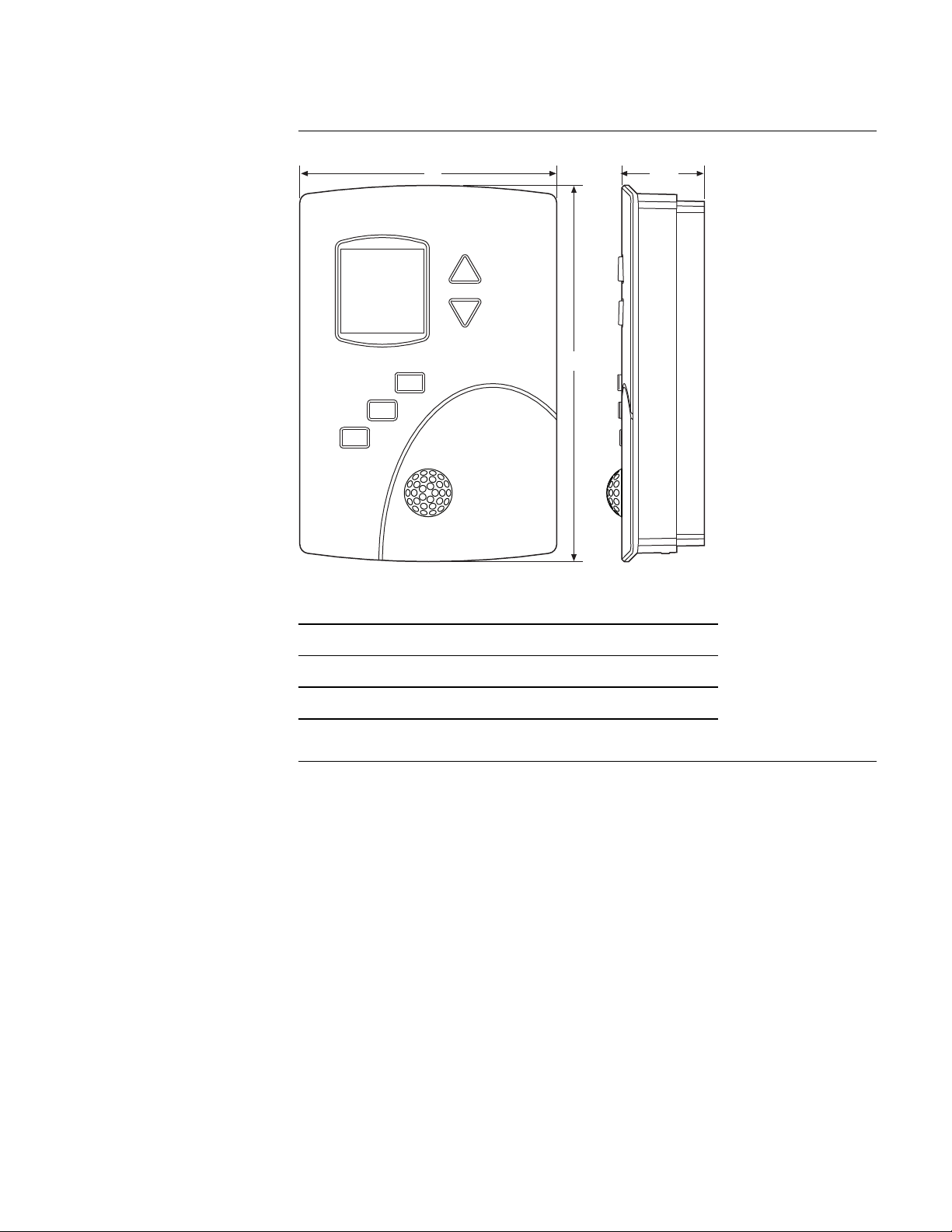
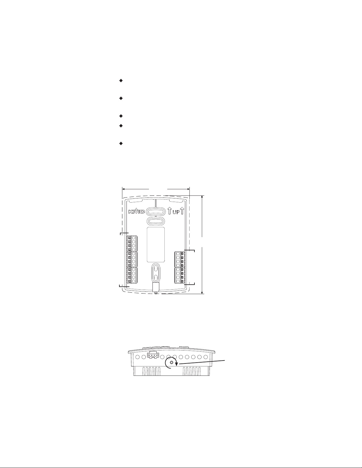
Dimensions
Table 1–1 AppStat Dimensions
A B C
3.50 in. 5.12 in. 1.12 in.
89 mm 130 mm 29 mm
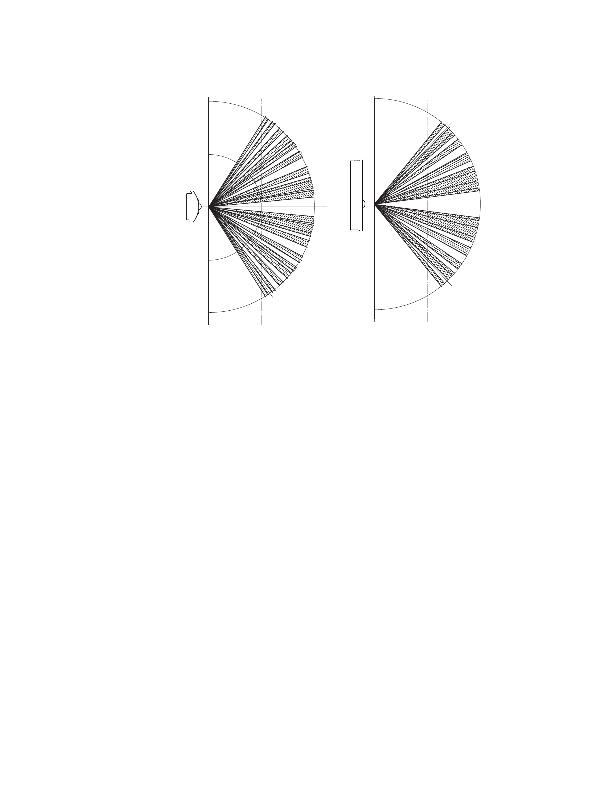
Motion sensor
Motion sensors are options available only on select models.
Detector type Passive infrared
Range 33 feet (10 meters). See the following
diagrams.
Revision G 11
Page 12
10 m
32.8 ft
10 m
32.8 ft
0°
46.5
°
Y
55
°
10 m
32.8 ft
10 m
32.8 ft
X
0°
Side viewTop view
Section 1: Introduction to the AppStat KMC Controls, Inc.
Installation accessories
The following accessories are available from KMC Controls, Inc.
XEE-6111-040 Single-hub 120 volt power transformer
XEE-6112-040 Dual-hub 120 volt power transformer
XEE-6311-075 120/240/277/480VAC, 24 VAC, 75 VA transformer
HMO-10000W White mounting plate kit for retrofit on horizontal
boxes or 4 x 4 handy boxes
12 Revision G
Page 13
BAC-4 _ _ _ CW0001
1 3-speed fan, On/off valves
2 3-speed fan, Modulating valves
3 3-speed or modulating fan,
modulating or On/Off valves
7 Modulating fan, On/Off valves
8 Modulating fan, Modulating Valves
0 Without humidity
2 With humidity
0 Without motion
2 With motion
Installation, Operation, and Application Guide for AppStat Section 1: Introduction to the AppStat
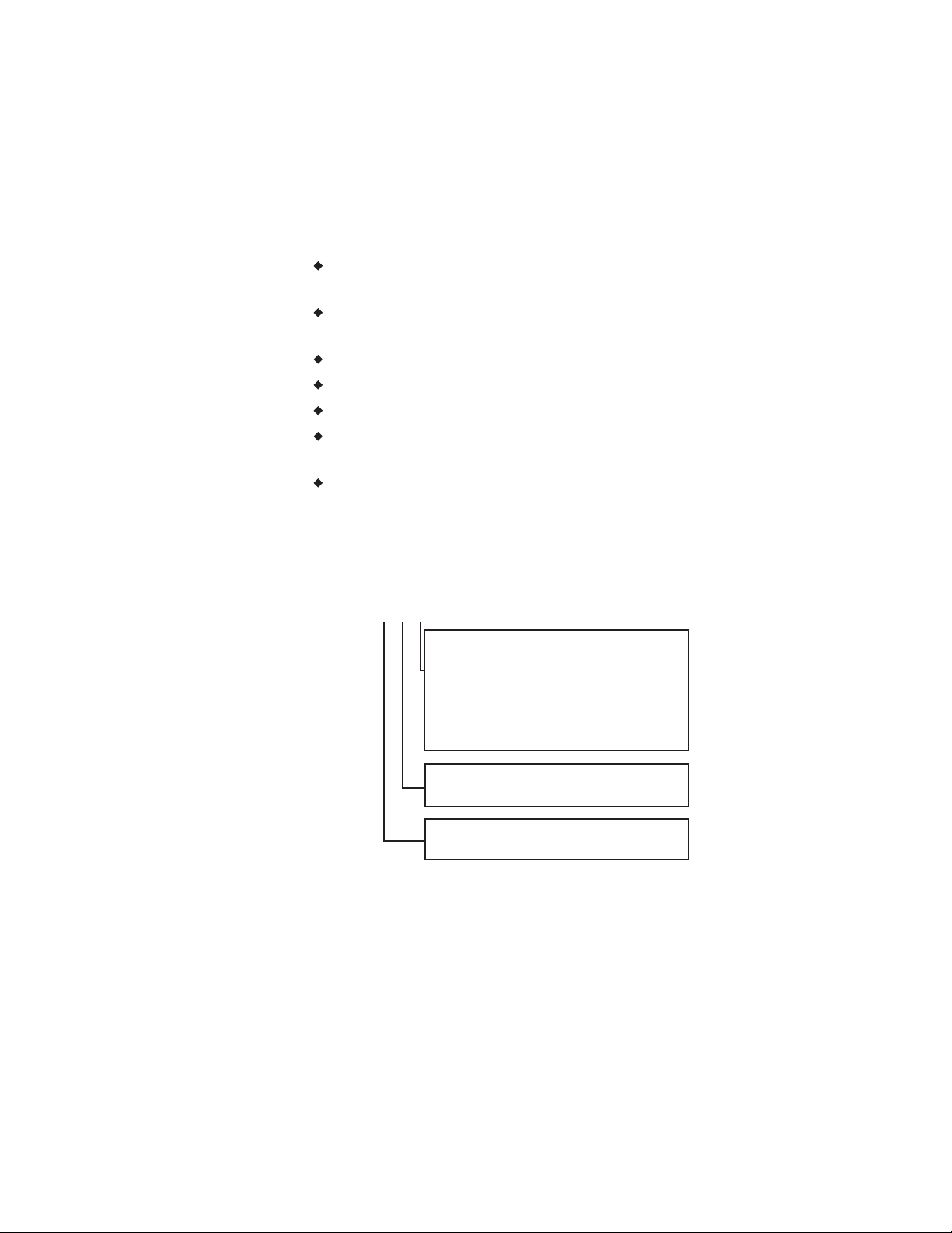
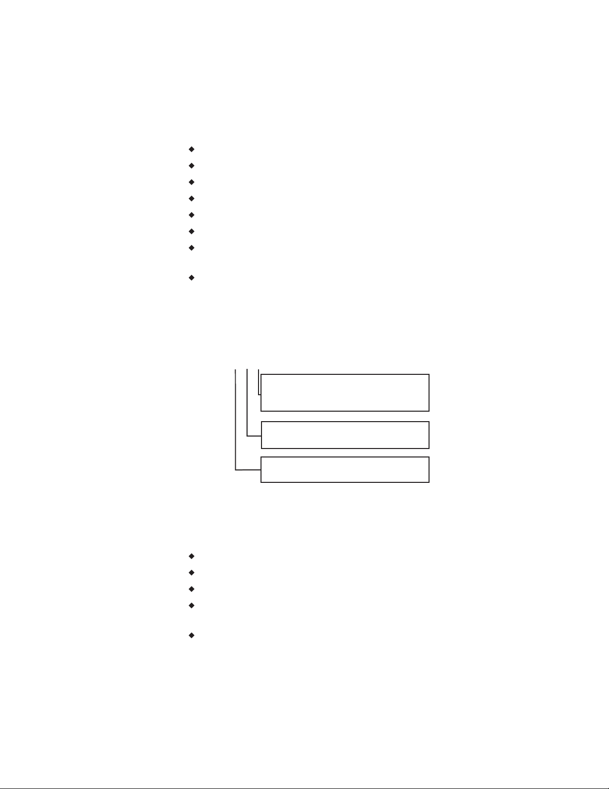
AppStat model numbers
Use the following charts to identify features in a specific AppStat model.
Fan coil units—The model numbers for these controllers end with "0001".
The inputs, outputs, and sequences of operation are configured and
programmed for the following functions.
Two-pipe heating and cooling with on/off valves, modulating valves or
both
Four-pipe heating and cooling with on/off valves, modulating valves or
both
Three-speed or modulating fan control
Automatic or manual fan control
Remote space temperature sensor
Local temperature setback mode based on optional built-in motion
sensor
Dehumidification on models with humidity sensor
See the following chart for the specific features included with each model.
Illustration 1–1 Model numbers for fan coil units
Revision G 13
Page 14
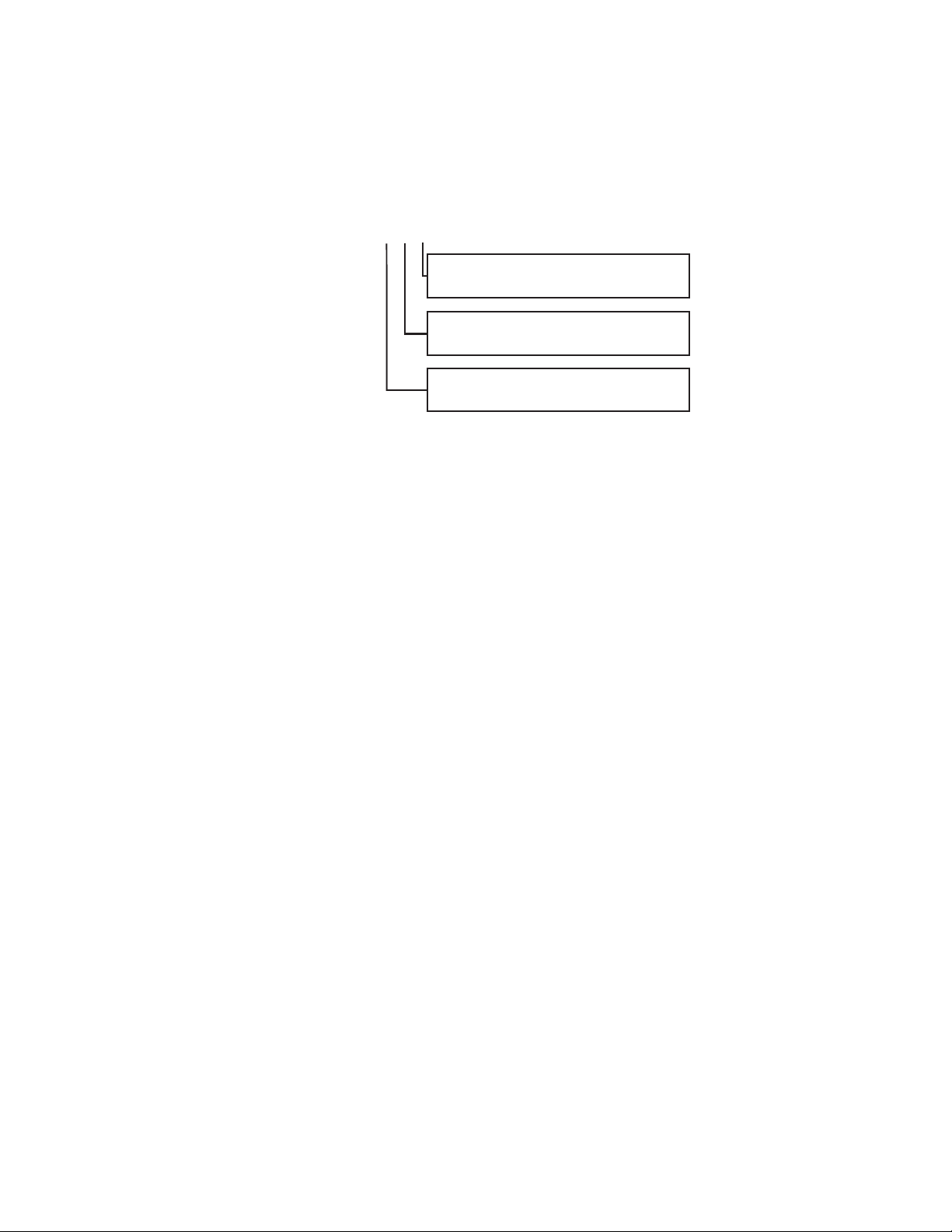
BAC-4 _ _ _ CW0002
1
2H/2C On/off valves or stages
3 2H/2C On/off or modulating valves
and economizer
0 Without humidity
2 With humidity
0 Without motion
2 With motion
Section 1: Introduction to the AppStat KMC Controls, Inc.
Roof top units—The model numbers for these controllers end with "0002".
These models control roof top or similar packaged or split unitary units. The
inputs, outputs, and sequences of operation are configured and programmed
for the following functions.
Automatic or manual fan control
Modulating valves or on/off heating and cooling valves.
One or two stage heating
One or two stage cooling
Optional economizer
Remote space temperature sensor
Local temperature setback mode based on optional built-in motion
sensor
Dehumidification on models with humidity sensor
See the following chart for the specific features included with each model.
Illustration 1–2 Model numbers for roof top units
14 Revision G
Heat pump units—The model numbers for these controllers end with "0003".
The inputs, outputs, and sequences of operation are configured and
programmed for the following functions.
Two stages of heat and two stages of cooling plus auxiliary heat
Optional economizer
Dehumidification-in models with auxiliary heat and a humidity sensor
Local temperature setback mode based on optional built-in motion
sensor
Automatic or manual fan control
Page 15
BAC-4 _ _ _ CW0003
1
3H/2C
3 3H/2C and economizer
0 Without humidity
2 With humidity
0 Without motion
2 With motion
Installation, Operation, and Application Guide for AppStat Section 1: Introduction to the AppStat
See the following chart for the specific features included with each model.
Illustration 1–3 Model numbers for heat pump units
Revision G 15
Page 16
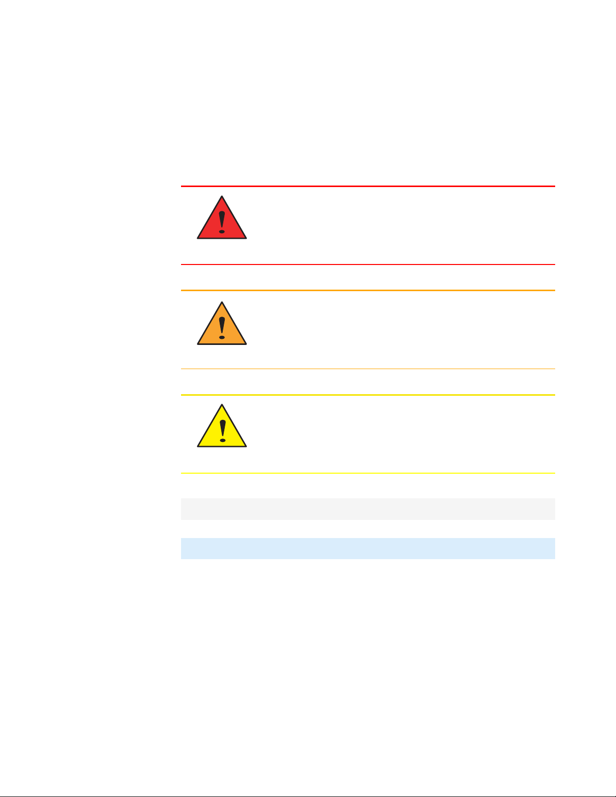
Danger
Warning
Caution
Section 1: Introduction to the AppStat KMC Controls, Inc.
Safety considerations
KMC Controls, Inc. assumes the responsibility for providing you a safe
product and safety guidelines during its use. Safety means protection to all
individuals who install, operate, and service the equipment as well as
protection of the equipment itself. To promote safety, we use hazard alert
labeling in this manual. Follow the associated guidelines to avoid hazards.
Danger represents the most severe hazard alert. Bodily
harm or death will occur if danger guidelines are not
followed.
Warning represents hazards that could result in severe
injury or death.
Caution indicates potential personal injury, equipment
damage, or property damage if instructions are not followed.
Note: Notes provide additional information that is important.
Tip: Provides programing tips and shortcuts that may save time.
16 Revision G
Page 17
Installation, Operation, and Application Guide for AppStat
Sec tion 2: Installing the AppS tat
This section provides important instructions and guidelines for installing
the AppStat. Carefully review this information before installation begins.
Installing the sensors includes the following topics that are covered in this
section.
Planning for motion sensing on page 17
Mounting the AppStat on page 18
Connecting inputs on page 20
Connecting outputs on page 24
Connecting power on page 28
Maintenance on page 29
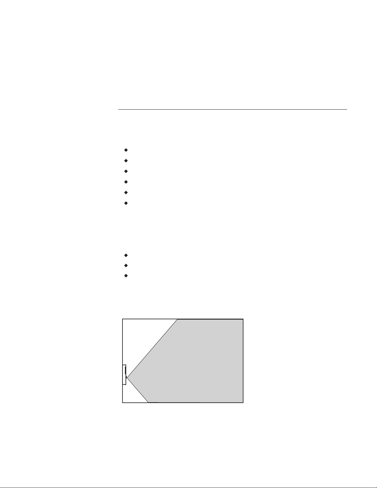
Planning for motion sensing
For models with a motion sensor mount the AppStat on a wall that will have
an unobstructed view of the typical traffic in the coverage area. When
choosing a location, do not install the sensor in the following areas.
Behind curtains or other obstructions
In locations that will expose it to sunlight or heat sources
Near a heating or cooling inlet or outlet.
For details on the coverage pattern, see Specifications on page 8.
Illustration 2–1 Typical motion sensing coverage area
Revision G 17
Page 18

Section 2: Installing the AppStat KMC Controls, Inc.
The effective detection range is approximately 10 meters or 33 feet. Factors
that may reduce the range include:
The difference between the surface temperature of the object and the
background temperature of the room is too small.
Object movement in a direct line toward the sensor.
Very slow or very fast object movement.
Obstructions as shown in the illustration Typical motion sensing coverage
area on page 17.
False detections may be triggered by:
The temperature inside the detection range suddenly changes because of
the entry of cold or warm air from an air-conditioning or heating unit.
The sensor being directly exposed to sunlight, an incandescent light, or
other source of far-infrared rays.
Small animal movement.
Mounting the AppStat
For the most accurate performance, install the AppStat on an inside wall
where it can sense the average room temperature. Avoid locations with direct
sunlight, heat sources, windows, air vents, and air circulation or obstructions
such as curtains, furniture, etc.
The AppStat must not be:
Mounted on an exterior wall.
Mounted on or near an object with large a thermal mass such as a
concrete block wall.
Blocked from normal air circulation by obstructions.
Exposed to heat sources such as lights, computers, copiers, or coffee
makers, or to direct sunlight at any time of the day.
Exposed to drafts from windows, diffusers, or returns.
Exposed to air flow through connecting conduits or empty spaces behind
walls.
For models with motion sensing, see the topic, Planning for motion sensing.
18 Revision G
Page 19
A
5.12 in.
130 mm
3.50 in.
89 mm
Inputs and
network
Power and outputs
Turn clockwise to remove
from base.
Installation, Operation, and Application Guide for AppStat Section 2: Installing the AppStat
Rough-in preparation
Complete rough-in wiring at each location before mounting an AppStat. This
includes the following steps.
Install the supplied mounting base directly to a wall, a vertical electrical
box, or a box with a wall plate kit.
Routing the connecting cable or cables from the AppStat to the
equipment it is controlling.
If required, install an appropriate wall plate kit.
Block leaks and airflow from conduits with plumber’s putty or similar
material.
If replacing an existing thermostat, label existing wires for reference
when removing the existing thermostat.
Illustration 2–2 AppStat mounting base details
Installing the AppStat
To install the controller on a mounting base, do the following:
1. Turn the Allen screw in the base of the sensor clockwise until it clears
the case.
2. Swing the AppStat away from the mounting base to remove it.
3. Route wiring for the AppStat through the mounting base.
Revision G 19
Page 20
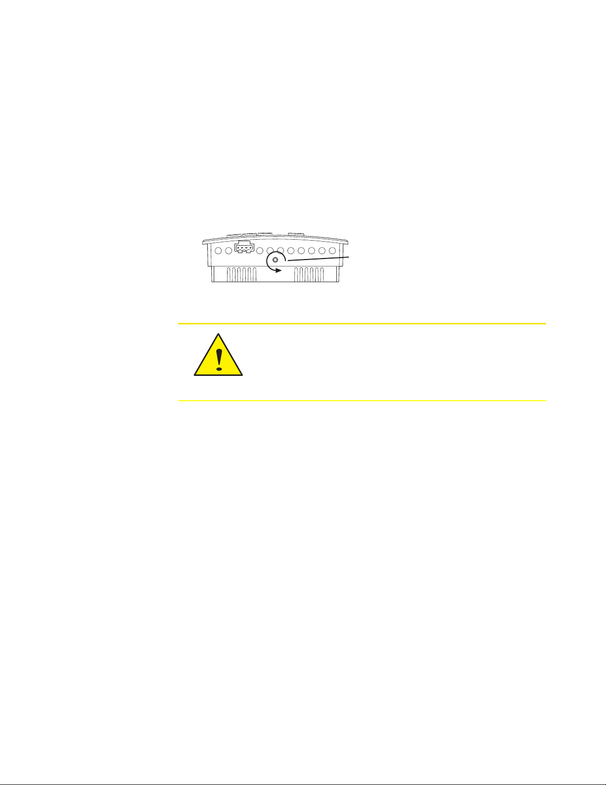
Turn counterclockwise
until the screw engages
the base.
Caution
Section 2: Installing the AppStat KMC Controls, Inc.
4. Position the base with the embossed UP toward the ceiling and fasten it
directly to a vertical 2x4 inch electrical box. For horizontal boxes or
4x4 applications, use a wall plate kit. See Installation accessories on page
12 for part numbers.
5. Connect the wires for the AppStat to the terminals in the mounting base.
6. Place the top of the sensor over the top of the mounting base and swing
it down over the Allen screw bracket. Be careful not to pinch any wiring.
7. Turn the Allen screw counterclockwise until it backs out of the mounting
base and engages the case.
To prevent mounting screw heads from touching the circuit
board in the controller, use only the mounting screws
supplied with the controller. Using screws other than the
type supplied may damage the AppStat.
Connecting inputs
The inputs for the AppStat are configured for specific functions and do not
require set up in the field. Not all inputs are required for every model or
application. See the topic BACnet objects on page 114 for the configuration
properties of the input objects.
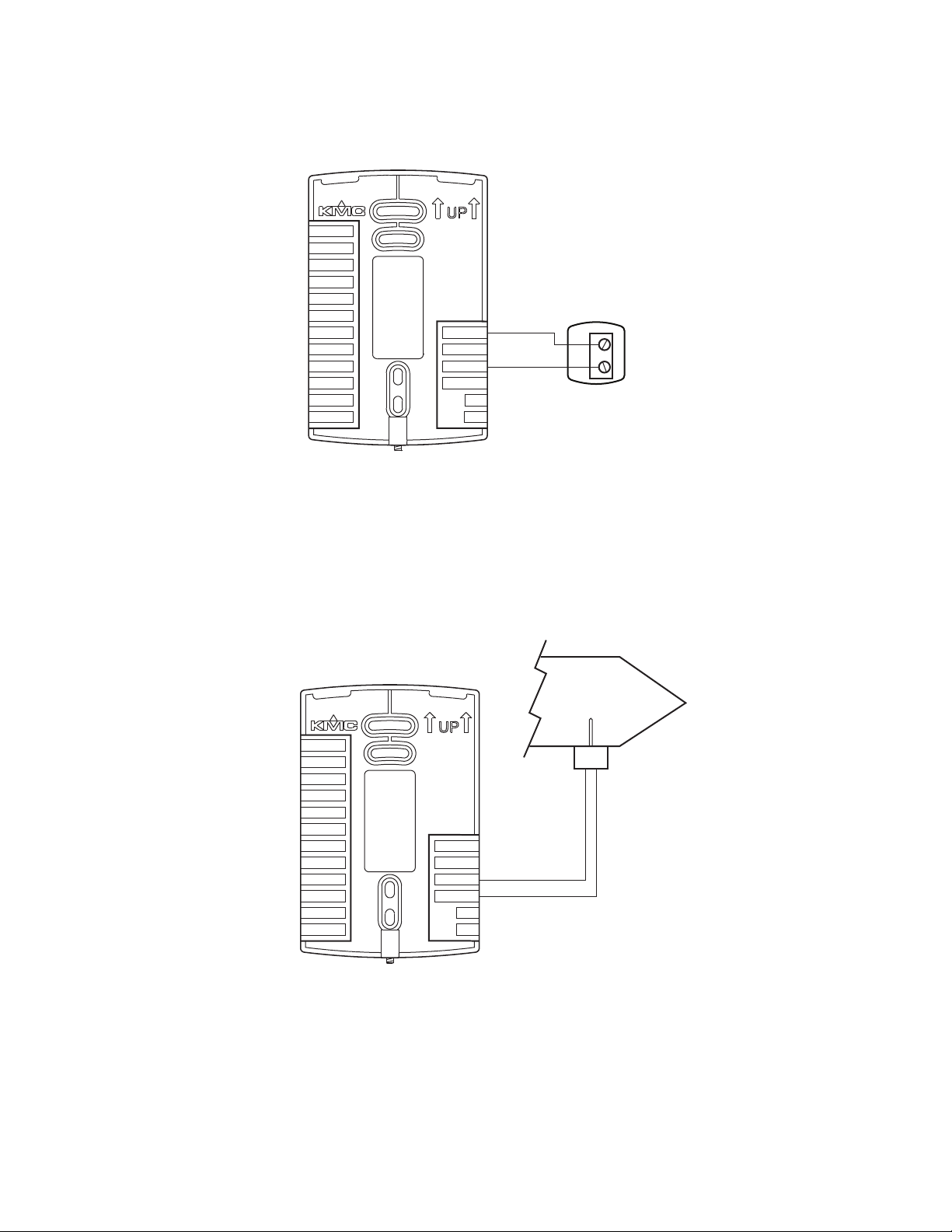
Remote space temperature sensor (optional)
Connect a 10kΩ, TypeII thermistor temperature sensor to the remote space
temperature (RS) input and ground (GND) terminals. The input includes the
internal pull-up resistor. An STE-6011W10 sensor is suitable for this
application. Follow the instructions supplied with the sensor for installation.
When a remote space temperature input is connected to the AppStat, the
remote temperature is used instead of the internal temperature sensor.
20 Revision G
Page 21
STE-6011W10
or equivalent
MS/TP
+B
A
RS
WST
GND
DAT
COM
FAN-L
FAN-M
FAN-H
R
BO4
BO5
GND
AO6
AO8
AO7
24VAC
STE-1405 or
equivalent
DAT
MS/TP
+B
A
RS
WST
GND
DAT
COM
FAN-L
FAN-M
FAN-H
R
BO4
BO5
GND
AO6
AO8
AO7
24VAC
Installation, Operation, and Application Guide for AppStat Section 2: Installing the AppStat
Illustration 2–3 Wiring for remote space temperature sensor
Discharge air temperature sensor
Connect a 10kΩ, Type III thermistor temperature probe to the discharge air
temperature (DAT) input. The input includes the internal pull-up resistor. An
STE-1405 sensor is suitable for this application. Follow the instructions
supplied with the sensor for installation.
Illustration 2–4 Wiring for Discharge Air Temperature Sensor
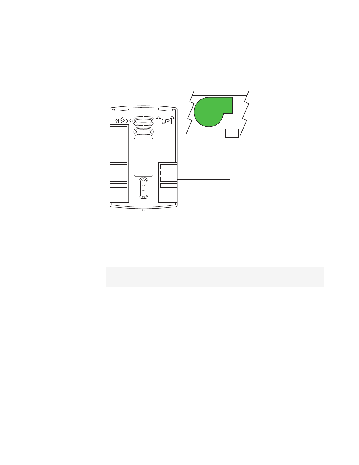
Fan status switch (optional)
Connect a Normally Closed Fan Status switch to the Discharge Air
Revision G 21
Temperature (DAT) input and ground (GND) terminals. The input includes
the internal pull-up resistor. A CSE-1102 differential pressure switch is
Page 22
FST
N.C Fan Status
CSE-1102
FAN
MS/TP
+B
A
RS
WST
GND
DAT
COM
FAN-L
FAN-M
FAN-H
R
BO4
BO5
GND
AO6
AO8
AO7
24VAC
Section 2: Installing the AppStat KMC Controls, Inc.
suitable for this application. Follow the instructions supplied with the switch
for installation.
Illustration 2–5 Wiring for a fan status switch
Water temperature sensor
Connect a 10kΩ, Type III thermistor temperature probe to the water
temperature (WST) input. The input includes the internal pull-up resistor. An
STE-1455 sensor is suitable for this application. Follow the instructions
supplied with the sensor for installation.
Note: The water temperature sensor is a required input sensor for 2-pipe fancoil
units.
22 Revision G
Page 23
STE-1455 or
equivalent
WST
MS/TP
+B
A
RS
WST
GND
DAT
COM
FAN-L
FAN-M
FAN-H
R
BO4
BO5
GND
AO6
AO8
AO7
24VAC
STE-1451 or
equivalent
MS/TP
+B
A
RS
OAT
GND
DAT
ECON
G
Y1
Y2
RC
W1
W2
RH
AO6
AO7
COM
24VAC
OAT
Installation, Operation, and Application Guide for AppStat Section 2: Installing the AppStat
Illustration 2–6 Wiring for a water temperature sensor
Outside air temperature
Connect a 10kΩ, Type III thermistor temperature probe to the outside air
temperature (OAT) input. The input includes the internal pull-up resistor. An
STE-1451 sensor is suitable for this application. Follow the instructions
supplied with the sensor for installation.
Illustration 2–7 Wiring for an outside air temperature sensor
Revision G 23
Page 24
Caution
Section 2: Installing the AppStat KMC Controls, Inc.
Connecting outputs
The AppStat outputs are model dependent and are configured for specific
applications.
No field programming or set up is required or possible.
Depending on model and application, the AppStat outputs are designed
for either 24 voltAC or 0-10 voltDC loads.
The outputs may represent analog or digital signals.
See the topic BACnet objects on page 114 for the configuration properties
of the output objects.
Improperly connecting loads or equipment to output
terminals may damage the equipment. Connect only as
shown in the following diagrams or application drawings.
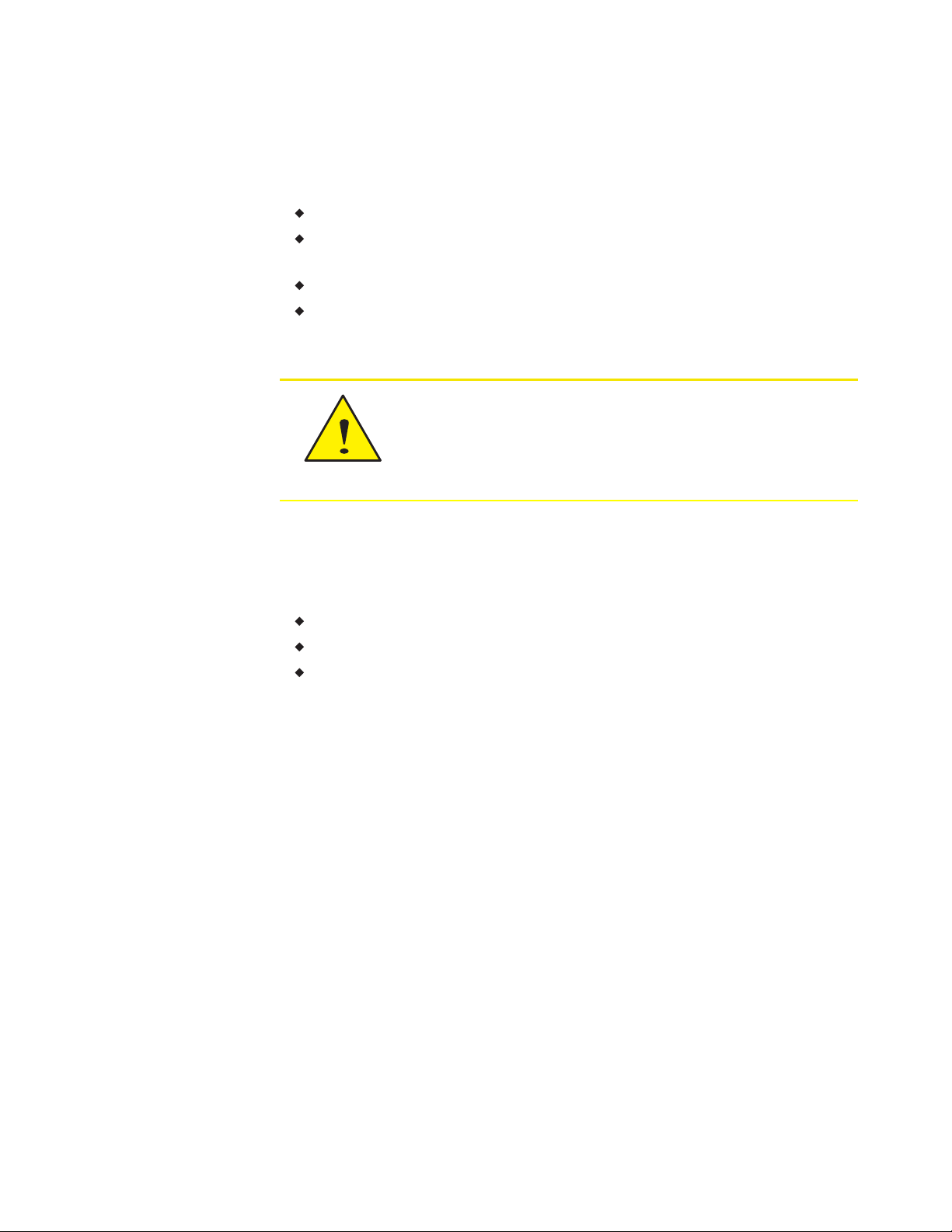
Connecting to a three-speed fan
The following diagram shows the connections for a three-speed fan. The fan
circuits must be a 24-volt AC pilot duty only.
For a single-speed fan, use only the FAN-L connection.
For a two-speed fan, use the FAN-L and FAN-H connections.
For a three-speed, use FAN-L, FAN-M, and FAN-H
24 Revision G
Page 25
High
Med
LoW
Com
24 VAC
MS/TP
+B
A
RS
WST
GND
DAT
COM
FAN-L
FAN-M
FAN-H
R
BO4
BO5
GND
AO6
AO8
AO7
24VAC
Installation, Operation, and Application Guide for AppStat Section 2: Installing the AppStat
Illustration 2–8 Connections to a three-speed fan
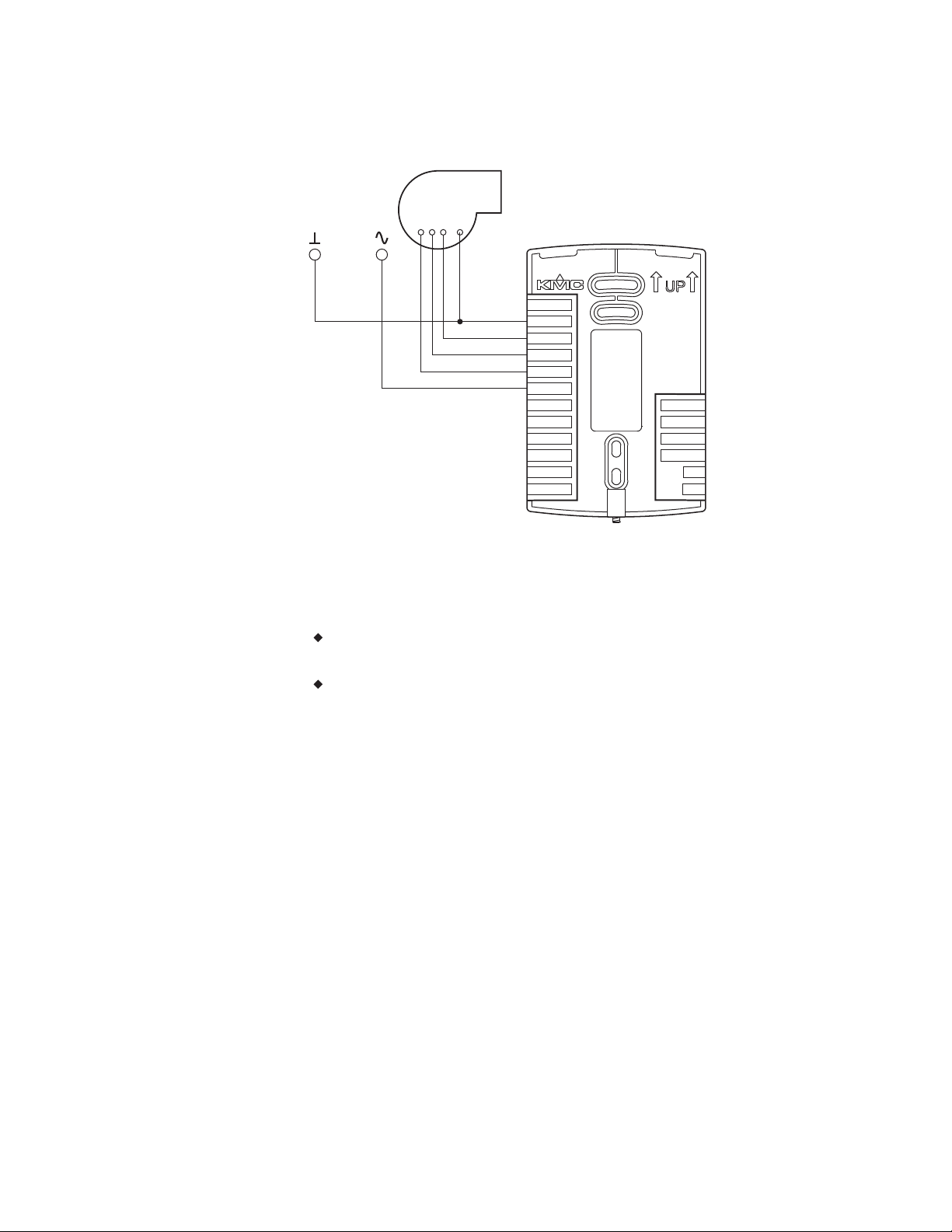
Connecting to a modulating fan
The following diagram shows the connections for a modulating speed fan.
The fan start circuit must be a 24-volt AC circuit. Connect it to the
FAN-L output.
The speed control is a 0-10 volt DC analog output.
Revision G 25
Page 26
Speed
Start
Com
24 VAC
MS/TP
+B
A
RS
WST
GND
DAT
COM
FAN-L
FAN-M
FAN-H
R
BO4
BO5
GND
AO6
AO8
AO7
24VAC
Cooling Heating
24 VAC
MS/TP
+B
A
RS
WST
GND
DAT
COM
FAN-L
FAN-M
FAN-H
R
BO4
BO5
GND
AO6
AO8
AO7
24VAC
Section 2: Installing the AppStat KMC Controls, Inc.
Illustration 2–9 Connections for a modulating fan
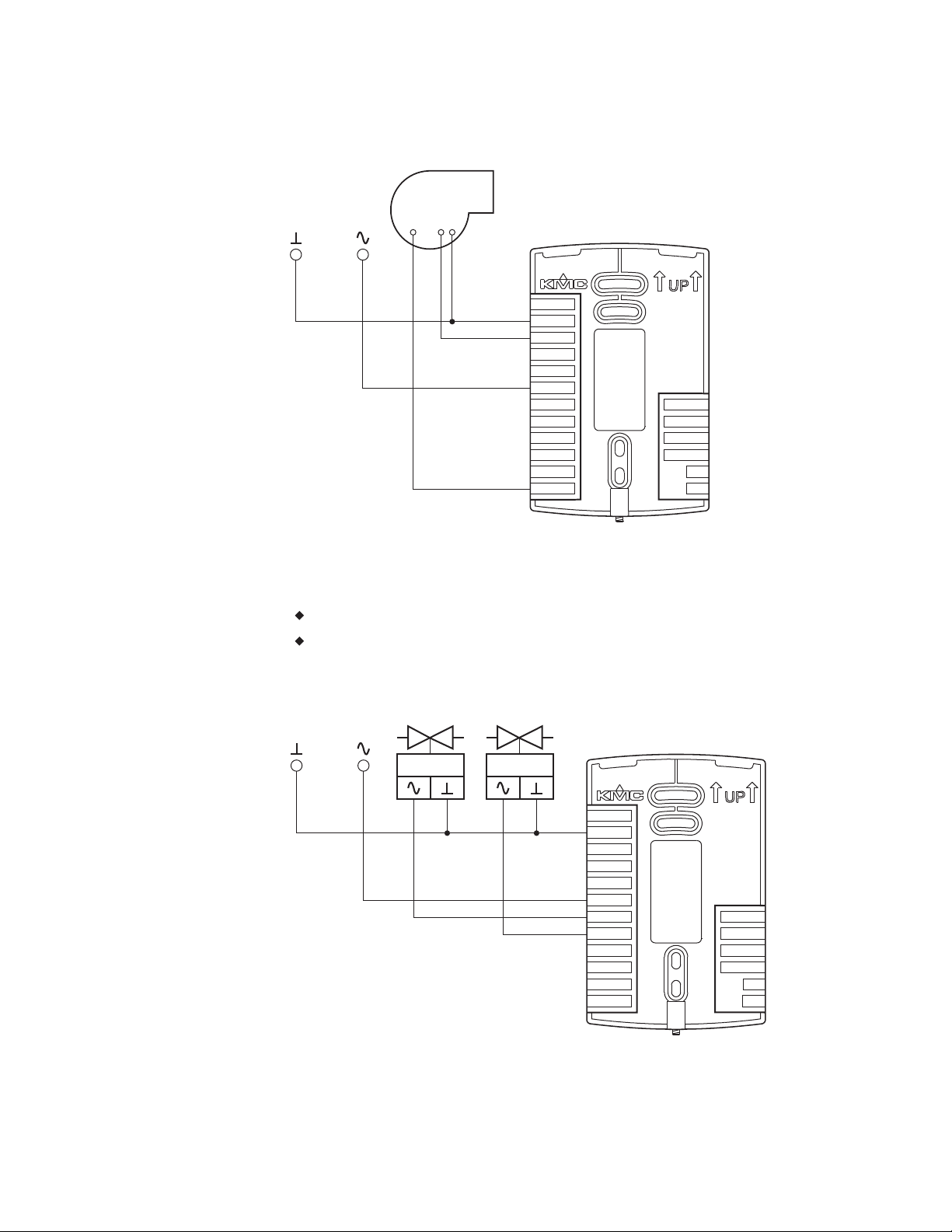
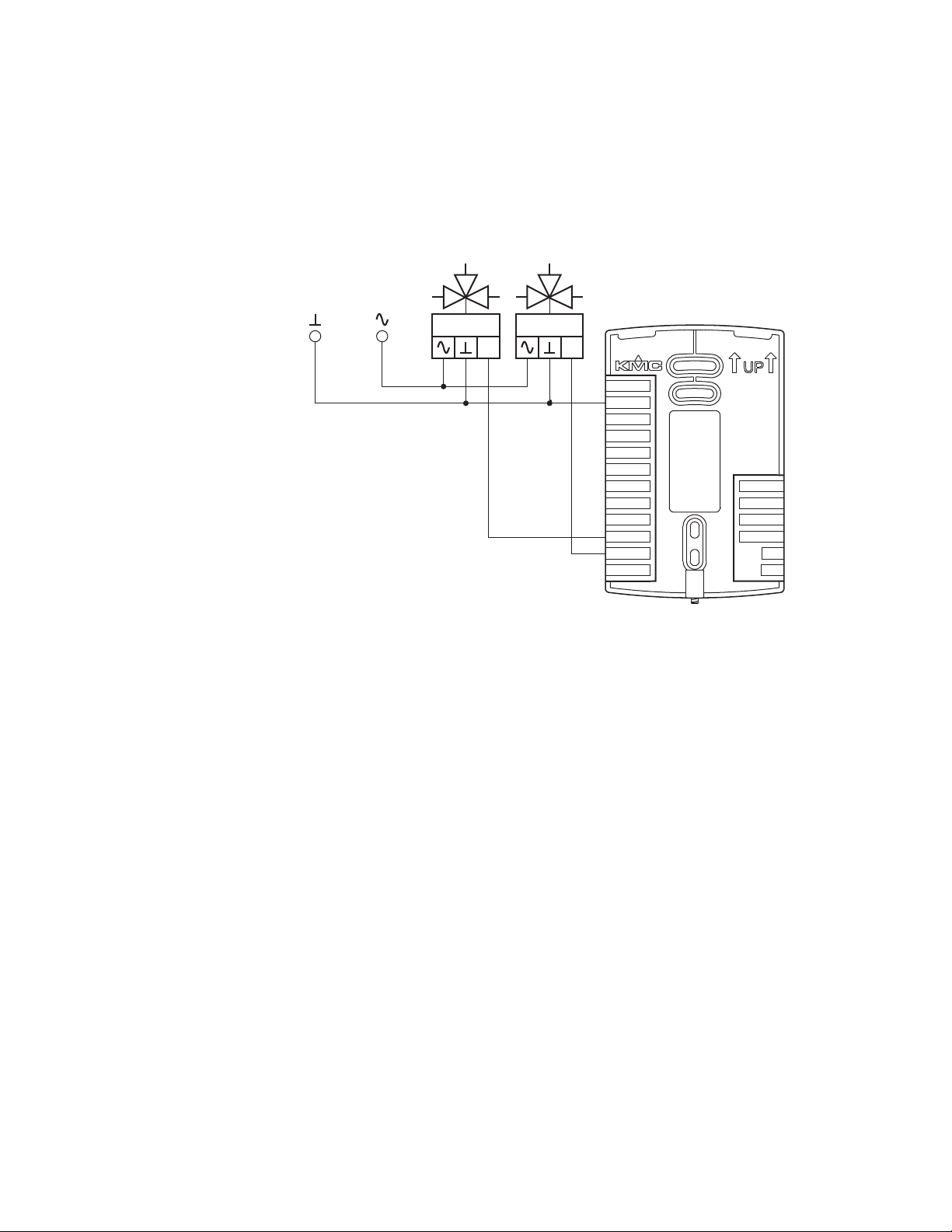
Connecting on/off valves
The following diagram shows the connections on/off valves.
The valves are activated by 24-volts AC.
The outputs are 24-volt relays.
Illustration 2–10 Connections to on/off valves
26 Revision G
Page 27
0-10
VDC
0-10
VDC
Cooling Heating
24 VAC
MS/TP
+B
A
RS
WST
GND
DAT
COM
FAN-L
FAN-M
FAN-H
R
BO4
BO5
GND
AO6
AO8
AO7
24VAC
Installation, Operation, and Application Guide for AppStat Section 2: Installing the AppStat
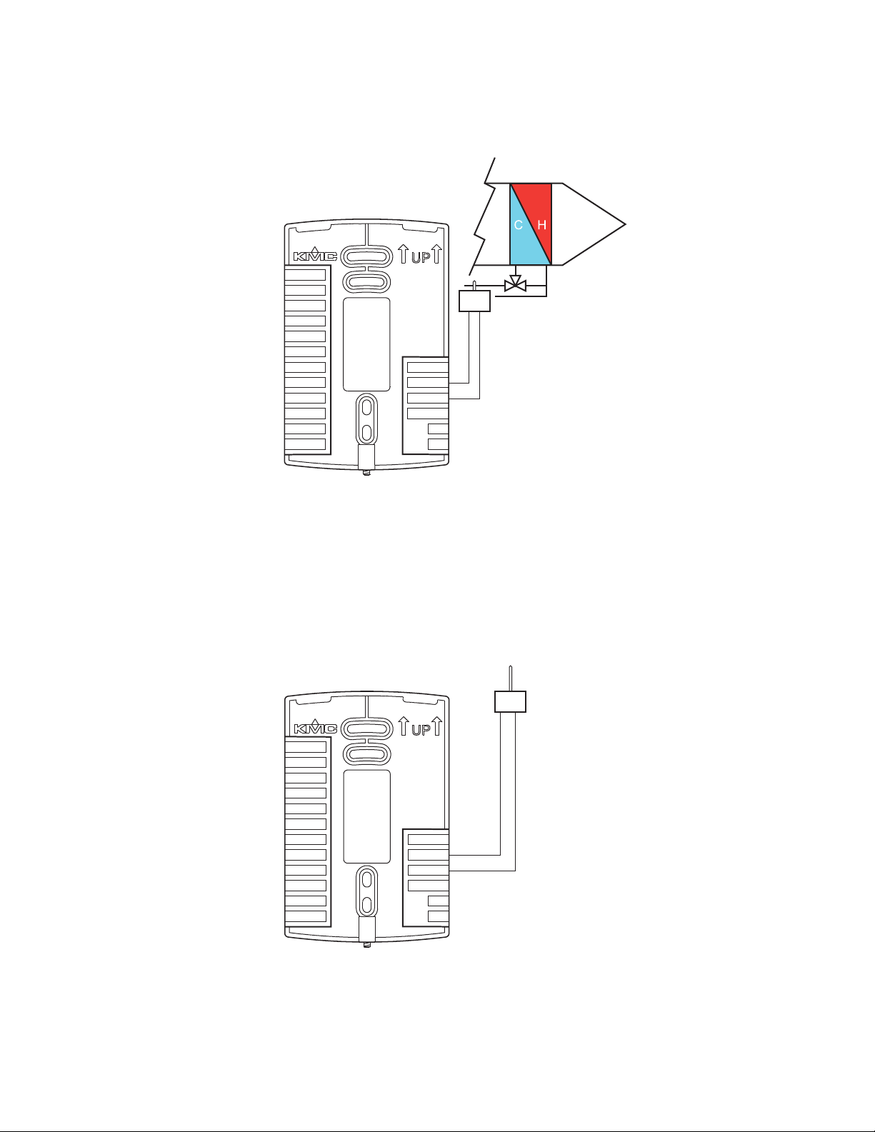
Connecting to modulating valves
The following diagram shows the connections for a modulating mixing
valves. The valve control signal is a 0-10 volt analog output.
Illustration 2–11 Modulating heating and cooling valves
Revision G 27
Page 28
0-10
VDC
24 VAC
MS/TP
+B
A
RS
OAT
GND
DAT
ECON
G
Y1
Y2
RC
W1
W2
RH
AO6
AO7
COM
24VAC
Section 2: Installing the AppStat KMC Controls, Inc.
Connecting an economizer
The following diagram shows the connections for an economizer. The damper
control signal is a 0-10 volt analog output.
Illustration 2–12 Wiring for an economizer
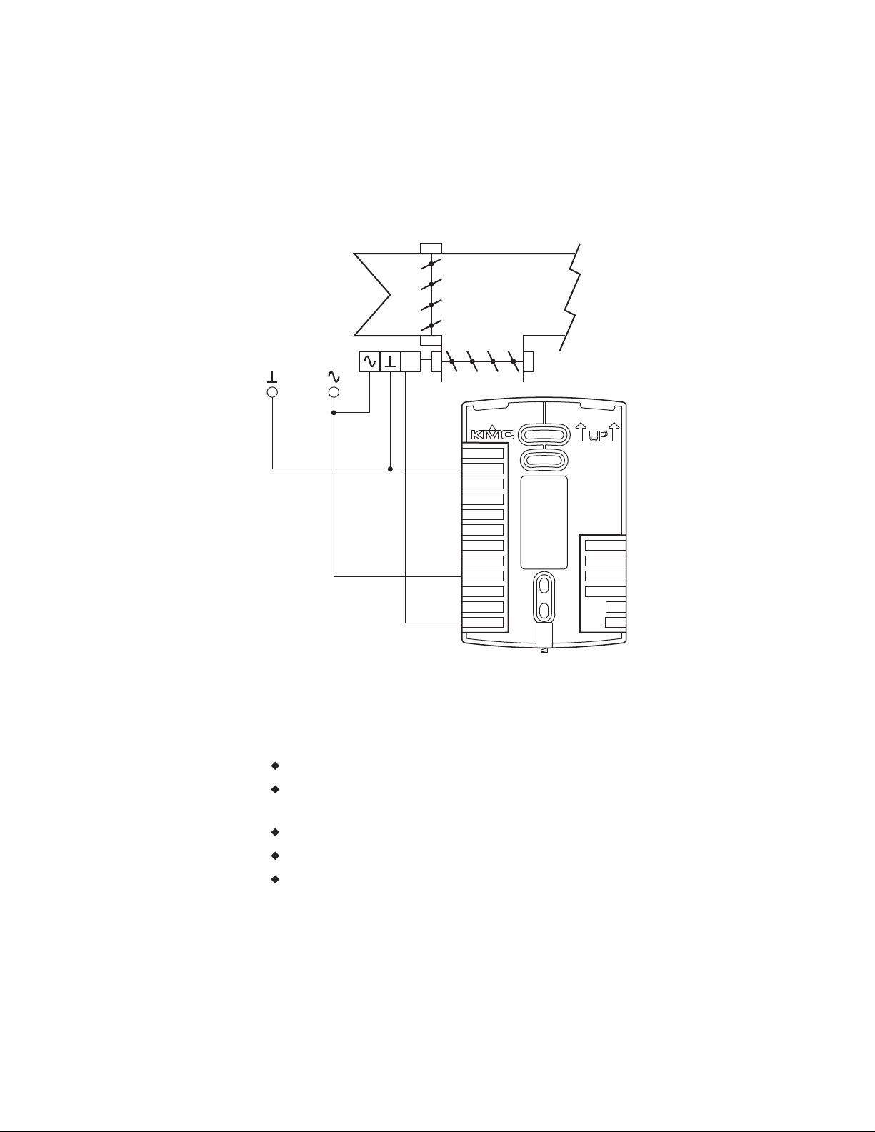
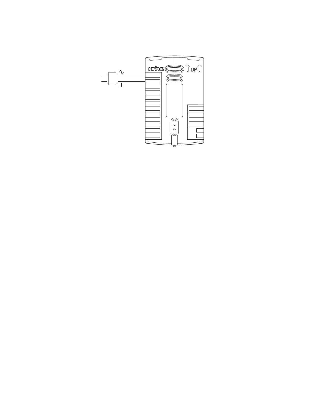
Connecting power
The AppStat requires an external, 24 volt, AC power source. Use the
following guidelines when choosing and wiring transformers.
Use only a Class-2 transformer of the appropriate size to supply power.
KMC Controls recommends powering the AppStat from a dedicated
controls transformer.
Connect the transformer’s neutral lead to the COM terminal.
Connect the AC phase lead to the 24VAC terminal.
Power is applied to the controller when the transformer is powered.
See Installation accessories on page 12 for a list of transformers available from
28 Revision G
KMC Controls, Inc.
Page 29
24 VAC
Class-2
Controls
transformer
MS/TP
+B
A
RS
WST
GND
DAT
COM
FAN-L
FAN-M
FAN-H
R
BO4
BO5
GND
AO6
AO8
AO7
24VAC
Installation, Operation, and Application Guide for AppStat Section 2: Installing the AppStat
Illustration 2–13 Wiring for AppStat power
Maintenance
Remove dust as necessary from the holes in the top and bottom. Clean the
display with soft, damp cloth and mild soap.
Revision G 29
Page 30

Section 2: Installing the AppStat KMC Controls, Inc.
30 Revision G
Page 31

COOLING SETPT
Up and down
buttons
Soft key
buttons
Soft key
bar
Optional
motion sensor
72
F
°
AUTO AUTO
DoneEnterCncl
Installation, Operation, and Application Guide for AppStat
Sec tion 3: Use r f u n c tio ns
This section covers topics for the end user in a facility.
AppStat user functions are limited to changing the following functions.
Active temperature setpoints
Fan operation
Changing between heating and cooling
Override scheduled occupancy or occupancy based on the schedule in
the AppStat.
Change the display between Fahrenheit and Celsius
Operating the AppStat
AppStat functions are accessible through a user interface consisting of simple,
context sensitive menus. The menus are opened and options are selected by
using the buttons and a color display on the front of the AppStat.
Pressing either the up button or down button changes a selection,
setting, or value.
Pressing the Enter button saves the selected setting or value. Typically
the Enter button is the middle of the three buttons below the display.
Saving a selection also advances to the next display.
Illustration 3–1 AppStat display and buttons
Revision G 31
Page 32

Section 3: User functions KMC Controls, Inc.
The three buttons below the display are defined by labels in the soft key bar.
Typically the buttons are designated for the following functions.
Back—Returns to the previous menu.
Cncl—Cancels current changes.
Done—Push this button at any point while entering a value. For example,
if you have entered the first two digits of a password and the remaining
two digits are correct, pushing Done completes the entry of the
password.
Enter—Pushing this button enters the selection and advances to the next
step.
Exit—Returns to temperature display.
The operating modes of the AppStat are represented by the display icons.
Table 3–1 Operating mode icons
Icon Description Mode
The fan icon rotates when the system
fan is operational. In systems with
multispeed fans the icon rotation is
the same regardless of speed. When
fan operation is set to automatic, the
word "Auto" is placed under the
icon.
Occupied—Occupancy is set to
occupied by the schedule maintained
in the controller.
Unoccupied—Occupancy is set to
unoccupied by the schedule
maintained in the controller.
Standby—The space is temporarily
unoccupied because of lack of
detected motion in the room.
Override—A user has entered
temperature setpoints that override
the unoccupied setpoints.
Fan
Occupancy
Occupancy
Occupancy
Occupancy
Cooling—The system will cool the
space until the cooling setpoint is
reach. The icon is in motion when
cooling is taking place.
32 Revision G
Heating/Cooling
Page 33

Installation, Operation, and Application Guide for AppStat Section 3: User functions
Operating mode icons (continued)
Icon Description Mode
Heating—The system will heat the
space until the heating setpoint is
reached. The icon is in motion when
heating is taking place.
Off System is off Heating/Cooling
Dehumidification—During
dehumidification the system will
heat and cool at the same time to
remove humidity and maintain the
active temperature setpoint. The icon
is in motion while dehumidification
is taking place.
Heating/Cooling
Heating/Cooling
Revision G 33
Page 34

F
°
70
AUTO AUTO
SECURITY
ADMIN LEVEL
0 0 0 0
Section 3: User functions KMC Controls, Inc.
Entering a user password
User functions may require a password consisting of four numbers. Once a
user password is entered it will remain active for 60-seconds after the last
button is pushed.
Enter a user password
Procedure Steps Display
1 Starting display
2 Enter the Level 1
password.
Start at the temperature display.
1.
Press any button on the AppStat. The display
changes to the Security User Level display.
2.
Press either the or button to change the
first digit of the password.
3.
Press the Enter button to select the next
digit. Repeat for all four digits.
4.
If the password is correct, the display will
advance to the first menu.
34 Revision G
Page 35

F
°
70
AUTO AUTO
F
°
68
HEATING SETPT
Done
Enter
Cncl
F
°
72
COOLING SETPT
Done
Enter
Cncl
Installation, Operation, and Application Guide for AppStat Section 3: User functions
Changing the active setpoints
To enter or change the active temperature setpoints you may need user
password. To enter the password, see Entering a user password on page 34.
Note: In the following procedure the current active setpoint–either cooling or
heating–is the first setpoint to change. Once that setpoint is entered, the
display advances to the next setpoint.
To change the operation of the fan, occupancy, or heating/cooling, see the
topic Setting the operating modes on page 36.
Change the active temperature setpoints
Procedure Steps Display
1 Starting display
2 Change the active
setpoints
Start at the temperature display.
Note:
The next step may require a user
password. See
34
.
1.
Press either the or button to change the
active temperature setpoint.
Entering a user password on page
Note: A user password may be required
after pushing the first button.
2.
Press the Enter button to save the value. The
display will advance to the next setpoint
3.
Press either the or button to change the
next setpoint.
4.
Press the Enter button to save the value. The
display will return to the temperature
display.
Revision G 35
Page 36

F
°
70
AUTO AUTO
Enter
Cncl
MODE: HEAT
COOL
AUTO
OFF
Enter
Cncl
MODE: EMERGENCY
HEAT
COOL
AUTO
OFF
Section 3: User functions KMC Controls, Inc.
Setting the operating modes
The operating modes set the following functions.
Fan operation
Changing between heating and cooling
Override scheduled occupancy or occupancy that has been set by a
schedule.
Change the display units from Fahrenheit to Celsius.
To change the occupied temperature setpoints, see the topic Changing the
active setpoints on page 35.
Set the operating modes
Procedure Steps Display
1 Starting display
2 Change the heating
or cooling mode.
Start at the temperature display.
Note:
The following procedures may require a
user password. See
page 34
1.
.
Push the button under the heating/cooling
Entering a user password on
icon.
Note: If a user password has previously been
entered or if the AppStat has not been set up
with a user password, entering a password is
not required.
2.
Press either the or button to select the
heating/cooling mode. The mode may be one
of the following.
Emergency—(Option) Turns on the auxiliary
heating in a heat pump unit.
Heat—The system will only heat the space.
Cool—The system will only cool the space.
Auto—The system will switch between
heating and cooling.
Heating/cooling icons
Off—The system is turned off.
3.
Press the Enter button to save the setting.
The display returns to the temperature
display.
36 Revision G
Page 37

Enter
Cncl
FAN: ON
AUTO
Enter
Cncl
FAN: HIGH
MED
LOW
AUTO
Installation, Operation, and Application Guide for AppStat Section 3: User functions
Set the operating modes (continued)
Procedure Steps Display
1.
3 Set the fan mode.
Push the button under the fan icon.
Note: If a user password has previously been
entered or if the AppStat has not been set up
Fan icon
with a user password, entering a password is
not required.
2.
Press the Enter button to select the next
digit. Repeat for all four digits.
3.
Press either the or button to select the
fan mode from the following options.
Auto—Sets the fan to run only when
1-speed fan option
there is a call for heat or cooling. The
word AUTO will be placed under the fan
icon.
On—Sets a single speed fan will run
continuously.
Low, Med, High—Sets the speed at which
3-speed or modulating fans will run
Multi-speed fan option
continuously.
4.
Press the Enter button to save the setting.
The display returns to the temperature
display.
Revision G 37
Page 38

F
°
65
AUTO AUTO
Enter
Cncl
LOCAL OVRD: ON
OFF
F
°
70
AUTO AUTO
°
21
c
.0
AUTO AUTO
Section 3: User functions KMC Controls, Inc.
Set the operating modes (continued)
Procedure Steps Display
4 Change the override
setpoint
Entering an override setpoint can only take
place if the AppStat is in the unoccupied mode.
1.
Push the button under the unoccupied icon
.
Note: If a user password has previously been
entered or if the AppStat has not been set up
with a user password, entering a password is
not required.
2.
Press either the or button to change the
first digit of the password.
3.
Press the Enter button to select the next
digit. Repeat for all four digits.
4.
Press either the or button to turn the
override on or off.
Override Off—The controller uses the
unoccupied setpoint as the active setpoint.
Override On—the controller changes to the
occupied setpoint which can then be
temporarily changed.
5.
Press the Enter button to save the setting.
5 Change the display
38 Revision G
units
Note: When the system is in the unoccupied
mode, changing the active setpoint will
automatically place the system in the
override mode.
To temporarily change the display units to
either Celsius or Fahrenheit, press and hold the
middle button under the display until the units
change.
Page 39

Installation, Operation, and Application Guide for AppStat
Sec tion 4: Co m m i s s io n ing f u n c t ions
This topics in this section are advanced topics for control technicians and
engineers. These topic cover procedures for the initial AppStat setup.
The AppStat commissioning functions are values and settings that are entered
during the installation and commissioning of a controller and the equipment
it is controlling. Typically these functions do not change after the installation
and commissioning process.
To set up the commissioning functions, you will need the following
information.
Information about the equipment
The sequence of operation for the equipment
The building automation system plans for controllers that are part of a
network.
Users may change the occupied heating and cooling setpoints without
accessing the commissioning functions. This procedure is covered in the topic
User functions on page 31.
Note: The instructions for the AppStat commissioning functions cover all of the
functions that can be set in the controller. Not all functions are available on
every model of controller. Consult the installation and operation manual
supplied with the controller to verify the application programming in the
AppStat.
Revision G 39
Page 40

F
°
70
AUTO AUTO
Push together for
commissioning
AUTO AUTO
70
F
°
SECURITY
ADMIN LEVEL
0 0 0 0
Enter
Cncl
MAIN
SETPOINT
SCHEDULE
SYSTEM
COMM
ADVANCED
Section 4: Commissioning functions KMC Controls, Inc.
Enter the commissioning mode
For access to the commissioning functions you will need to know Password 2.
If the controller has not been previously set up, no password is required.
A new Password 2 can be entered in the advanced commissioning
functions. See the topic Advanced options on page 60.
Enter the commissioning mode
Procedure Steps Display
1 Starting display
2 Enter the
commissioning
password
Start from the temperature display.
1.
Press the left and right buttons below the
display at the same time and hold them until
the display changes to the SECURITY USER
LEVEL display.
Note: If Password 2 has not previously been
entered, the display will change to the
MAINmenu.
2.
Press either the or button to change the
first digit of Password 2.
3.
Press the Enter button to select the next
digit. Repeat for all four digits. The Enter
button is the middle of the three buttons
below the display.
3 Select a
40 Revision G
commissioning
function
Access to the commissioning functions always
starts at the MAIN menu display.
Page 41

F
°
70
AUTO AUTO
SECURITY
ADMIN LEVEL
0 0 0 0
Enter
Cncl
MAIN
SETPOINT
SCHEDULE
SYSTEM
COMM
ADVANCED
Installation, Operation, and Application Guide for AppStat Section 4: Commissioning functions
Setting the commissioning setpoints
The commissioning setpoints set the operational setpoints and limits for the
AppStat. The functions of the setpoints and how they are used are describe in
the topic Room temperature setpoints on page 66. Setting commissioning
setpoints requires entering Password2 which is described in the topic Enter
the commissioning mode on page 40.
Note: Not all setpoints in the following procedure are applicable to all models of
AppStat. Those setpoints are marked as (optional).
Procedure to set the commissioning setpoints
Procedure Steps Display
1.
1 Starting display
Start at the temperature display.
2.
Enter Password 2. The display changes to the
MAIN menu display.
2 Choose and set the
setpoints.
1.
From the MAIN menu , press either the or
button to select SETPOINTS.
2.
Press Enter. The SETPOINT menu opens
3.
Choose and set each of the following
setpoints.
Revision G 41
Page 42

Back
Enter
Cncl
SETPOINT
OCC COOL
OCC HEAT
UNOCC COOL
UNOCC HEAT
MIN COOLING
MAX HEATING
DIFFERENTIAL
Section 4: Commissioning functions KMC Controls, Inc.
Procedure to set the commissioning setpoints (continued)
Procedure Steps Display
OCC COOL—The cooling setpoint that is
used as the active setpoint when the system
is occupied.
OCC HEAT—The heating setpoint that is
used as the active setpoint when the system
is occupied.
UNOCC COOL—The cooling setpoint that is
used as the active setpoint when the system
is unoccupied.
UNOCC HEAT—The heating setpoint that is
used as the active setpoint when the system
is unoccupied.
MIN COOLING—The minimum cooling
setpoint that a user can select as the active
setpoint.
MAX HEATING—The maximum heating
setpoint that a user can select as the active
setpoint.
DIFFERENTIAL—The minimum value
between the cooling or heating setpoints.
The AppStat will always maintain this
difference between setpoints.
STBY OFFSET—(optional) A value used to
calculate the standby setpoint. The standby
setpoint is calculated by adding or
subtracting the offset value to or from the
value of the occupied setpoint.
DEHUM SETPOINT—(optional) Sets the
setpoint for dehumidification.
Dehumidification starts when the relative
humidity is above the dehumidification
setpoint.
DEHUM DEADBAND—(optional) The
system will remain in dehumidification until
the relative humidity falls below a value of
dehumidficaion setpoint minus the
dehumidification deadband value.
42 Revision G
Page 43

F
°
70
AUTO AUTO
SECURITY
ADMIN LEVEL
0 0 0 0
MAIN
SETPOINT
SCHEDULE
SYSTEM
COMM
ADVANCED
BackEnterExit
COMM
DEVICE ID
MAC
BAUD
BackEnterExit
D ID: 0000001
DoneEnterEnter
Installation, Operation, and Application Guide for AppStat Section 4: Commissioning functions
Set up communications
Setting BACnet communications properties is required only if the AppStat is
integrated into a network with other BACnet controllers. Entering the
communications properties requires entering Password 2 which is described
in the topic Enter the commissioning mode on page 40.
See the topic Connecting to an MS/TP network on page 121 for network
wiring details.
Set BACnet communication properties
Procedure Steps Display
1.
1 Starting display
Start at the temperature display.
2.
Enter Password 2. The display changes to the
MAIN menu display.
2 Change the network
communication
properties.
1.
From the MAIN menu , press either the or
button to select COMM.
2.
Press Enter. The COMMmenu opens.
3.
Choose and set the following properties.
l DEVICE ID—This is the BACnet device
instance. The device instance must be
within the range of 1 to 4,194,302.
l MAC—The MAC address must be in the
range of 1-127.
l BAUD—Set to match other devices on
the BACnet MS/TP network. The choices
are Auto, 9600, 19,200, 38,400, or 76,800.
Note: After changing a communication
property the AppStat will reset.
Revision G 43
Page 44

MAC: 1
DoneEnterEnter
BAUD: 76800
38400
19200
9600
Auto
DoneEnterCncl
Section 4: Commissioning functions KMC Controls, Inc.
Set BACnet communication properties (continued)
Procedure Steps Display
44 Revision G
Page 45

F
°
70
AUTO AUTO
SECURITY
ADMIN LEVEL
0 0 0 0
MAIN
SETPOINT
SCHEDULE
SYSTEM
COMM
ADVANCED
BackEnterExit
SCHEDULE
SET CLOCK
SETPOINT HOLD
ENTIRE WEEK
WEEKDAYS
WEEKEND
INDV DAYS
HOLIDAYS
DelEnterExit
Installation, Operation, and Application Guide for AppStat Section 4: Commissioning functions
Set the time and date
Setting the time and date requires entering Password 2 which is described in
the topic Enter the commissioning mode on page 40.
Note: If the AppStat is connected to a BACnet network that includes a time service
master, the time and date are automatically set to the network time and
date.
To change the schedule, see the procedure Setting the occupancy schedule on
page 47.
Set the time and date
Procedure Steps Display
1.
1 Starting display
Start at the temperature display.
2.
Enter Password 2. The display changes to the
MAIN menu display.
1.
2 Select the
SCHEDULE menu.
From the MAIN menu , press either the or
button to select SCHEDULE.
2.
Press Enter. The SCHEDULE menu opens.
3.
Choose SET CLOCK and then press Enter.
The SET Clock menu opens.
Revision G 45
Page 46

SET CLOCK
DATE
TIME
UTC OFFSET
DST ENABLE
DST AUTO
DST START
DST END
BackEnterExit
Section 4: Commissioning functions KMC Controls, Inc.
Set the time and date (continued)
Procedure Steps Display
3 Choose a clock
function to set.
Choose one of the features in the SET CLOCK
menu to change the date, time, or Daylight
Saving Time (DST) setting.
DATE—The current calendar date.
TIME—Time is set according to a 12-hour
clock.
UTC OFFSET—Enter the time offset—in
minutes—between local standard time and
Universal Time Coordinated. The value of
the property ranges from -780 to +780
seconds. The time zones to the west of the
zero degree meridian are positive values;
those to the east are negative values. The
value of the UTC Offset property is
subtracted from the UTC received in a UTC
Time Synchronization service request to
calculate the correct local standard time.
DST ENABLE—Set to TRUE to enable
Daylight Saving Time and FALSE to use
standard time year around.
DST AUTO—When set to TRUE, the AppStat
automatically calculates the start and end
dates from relative dates. For example, set
DST START to the first Sunday in March
instead of a calendar date.
DST START and DST END—Enter the dates
and time to begin observing DST. If DST
AUTO is set to TRUE the dates are relative;
if set to FALSE the date is a calendar date.
46 Revision G
Page 47

F
°
70
AUTO AUTO
SECURITY
ADMIN LEVEL
0 0 0 0
MAIN
SETPOINT
SCHEDULE
SYSTEM
COMM
ADVANCED
BackEnterExit
Installation, Operation, and Application Guide for AppStat Section 4: Commissioning functions
Setting the occupancy schedule
The schedule in the AppStat controls the occupancy mode. If the schedule is
set to ON, the AppStat uses the occupied setpoint as the active setpoint. If the
schedule is OFF, the unoccupied setpoint is used.
Note: The schedule in the AppStat is a BACnet schedule object. If the AppStat is
connected to a BACnet network the schedule can be set up with a BACnet
operator workstation.
Setting the occupancy schedule requires entering Password2 which is
described in the topic Enter the commissioning mode on page 40.
To change the time and date, see the procedure Set the time and date on page
45.
Set up schedules
Procedure Steps Display
1.
1 Starting display
Start at the temperature display.
2.
Enter Password 2. The display changes to the
MAIN menu display.
1.
2 Select the
SCHEDULE menu.
Revision G 47
From the MAIN menu , press either the or
button to select SCHEDULE.
2.
Press Enter. The SCHEDULE menu opens.
Page 48

SCHEDULE
SET CLOCK
SETPOINT HOLD
ENTIRE WEEK
WEEKDAYS
WEEKEND
INDV DAYS
HOLIDAYS
BackEnterExit
ENTIRE WEEK
1: 12:00:00 AM ON
2:
--:--:---- ----
3:
--:--:---- ----
4:
--:--:---- ----
5:
--:--:---- ----
6:
--:--:---- ----
DelEnterExit
Section 4: Commissioning functions KMC Controls, Inc.
Set up schedules (continued)
Procedure Steps Display
1.
3 Choose and set a
weekly schedule.
From the SCHEDULE menu, choose one of
the following schedule entry methods to
enter a weekly schedule.
l ENTIRE WEEK—Sets the schedule for
all seven days of the week at one time.
l WEEKDAYS—Sets the schedule for
Monday to Friday. Saturday and Sunday
are not changed
l WEEKEND—Sets the schedule for
Saturday and Sunday. Monday to Friday
remain unchanged.
l INDIVIDUAL DAYS—Sets the schedule
for just the selected day of the week.
2.
Change the daily times and values in the
schedule to set the occupancy mode to either
ON or OFF.
l When finished with each pair push Enter
or Done.
l When finished with the schedule push
Exit to return to the SCHEDULE menu.
48 Revision G
Page 49

HOLIDAYS
HOL1
HOL2
HOL3
HOL4
HOL5
HOL6
HOL7
DelEnterExit
HOL2
DATE
DEC 12 2013
TYPE: DATE
DelEnterExit
HOL3
START DATE:
NOV 27 2013
END DATE:
DEC 12 2013
TYPE: DATE RANGE
DelEnterExit
HOL5
MON WK DAY:
OCT 31 THU
TYPE: WEEK N DAY
DelEnterExit
Installation, Operation, and Application Guide for AppStat Section 4: Commissioning functions
Set up schedules (continued)
Procedure Steps Display
4 Choose and set a
holiday schedule
Use a holiday schedule to override the values in
the weekly schedule. Months and years can be
entered as follows:
To choose ANY as the year, select the year
and push the down arrow past the current
year
For month the choices are any of the twelve
months of the year, ANY, EVEN, and ODD.
1.
From the SCHEDULE menu, choose
HOLIDAYS.
2.
From the HOLIDAYS list, choose a holiday
to edit.
3.
From the menu for the holiday, choose
l DATE—Snter a single date on which the
holiday schedule will override the values
of the weekly schedule.
l DATE RANGE—Enter a range of dates
on which the values and times listed in
the holiday schedule will override the
values of the weekly schedule.
l WEEK N DAY—A day of the week and
month on which the values and times
listed in the holiday schedule will
override the values of the weekly
schedule.
Revision G 49
Page 50

F
°
70
AUTO AUTO
SECURITY
ADMIN LEVEL
0 0 0 0
MAIN
SETPOINT
SCHEDULE
SYSTEM
COMM
ADVANCED
BackEnterExit
SYSTEM
LOCAL OVRD TIME
FAN OFF DELAY
OCCUPIED FAN
CL VALVE ACTION
HT VLV ACTION
FAN MAXIMUM
FAN MINIMUM
BackEnterExit
SYSTEM
LOCAL OVRD TIME
FAN OFF DELAY
OCCUPIED FAN
VLV ACTION
FAN MAXIMUM
FAN MINIMUM
AUX HEAT
BackEnterExit
BackEnterCncl
LOCAL OVRD TIME
2 60 mins
Section 4: Commissioning functions KMC Controls, Inc.
Set fan coil unit system options
The items in the system menu control application specific functions for fan coil
units. Entering the system options requires entering Password 2 which is
described in the topic Enter the commissioning mode on page 40.
Set up fan coil unit system options
Procedure Steps Display
1.
1 Starting display.
Start at the temperature display.
2.
Enter Password 2. The display changes to the
MAIN menu display.
1.
2 Choose and set the
fan coil system
options.
From the MAIN menu , press either the or
button to select SYSTEM.
2.
Press Enter. The SYSTEM menu opens.
3 Set the local override
time.
3.
Choose any of the following items.
LOCAL OVRD TIME
FAN OFF DELAY
OCCUPIED FAN
CL VALVE ACTION (Four-pipe only)
HT VLV ACTION (Four-pipe only)
VLV ACTION (Two-pipe only)
FAN MAXIMUM (Modulating fans only)
FAN MINIMUM (Modulating fans only)
FAN SPEEDS (Three speed fans only)
AUX HEAT (Two-pipe only)
From the SYSTEM menu choose LOCAL OVRD
TIME to set the time the AppStat will hold an
override temperature setpoint as the active
setpoint. At the end of the period, the AppStat
will use either an occupied or unoccupied
setpoint as the active setpoint.
50 Revision G
Page 51

BackEnterCncl
FAN OFF DELAY
2 2 mins
BackEnterCncl
OCCUPIED FAN:
ON
OFF
CL VLV ACTION:
NORMAL OPEN
NORMAL CLOSED
DelEnterCncl
HT VLV ACTION:
NORMAL OPEN
NORMAL CLOSED
DelEnterCncl
VLV ACTION:
NORMAL OPEN
NORMAL CLOSED
DelEnterCncl
Installation, Operation, and Application Guide for AppStat Section 4: Commissioning functions
Set up fan coil unit system options (continued)
Procedure Steps Display
4 Set the fan delay.
5 Set the occupied fan
control.
6 Set the valve action.
From the SYSTEM menu choose FAN DELAY
OFF to set the time the system fan will continue
to run after the last heating or cooling stage is
turned off.
From the SYSTEM menu choose OCCUPIED
FANto choose the following:
When ON, the fan will run continuously
when the schedule is occupied (On).
When the schedule is unoccupied (Off) the
fan will run only when there is a call for
heating or cooling.
Select one of the valve actions from the
SYSTEMmenu. Not all choices apply to every
application.
CL VALVE ACTION—(Four-pipe only)
HT VLV ACTION—(Four-pipe only)
VLV ACTION—(Two-pipe only)
Valve action selections are the same for all three
types of valves.
NORMAL OPEN—The valve changes from
fully open to fully closed as the AppStat
varies the valve output from 0 to 10 volts.
NORMAL CLOSED—The valve changes
from fully closed to fully open as the
AppStat varies the valve output from 0 to 10
volts.
Revision G 51
Page 52

BackEnterCncl
FAN MINIMUM:
35 %utoz
BackEnterCncl
FAN MAXIMUM:
100 %utoz
BackEnterCncl
FAN SPEEDS:
THREE SPEEDS
TWO SPEEDS
SINGLE SPEED
AUX HEAT:
Enable
Disable
DelEnterCncl
Section 4: Commissioning functions KMC Controls, Inc.
Set up fan coil unit system options (continued)
Procedure Steps Display
7 Set fan speeds for
modulating speed
fans.
8 Set fan speeds for
three-speed fans.
9 Enable auxiliary heat
Select FAN MINIMUM or FAN MAXIMUM
from the SYSTEM menu to set fan speed for
modulation fans.
FAN MINIMUM—Sets the slowest speed at
which the fan will run when a user sets the
fan speed to LOW.
FAN MAXIMUM—Sets the fastest speed at
which the fan will run when a user sets the
fan speed to HIGH.
The MED speed is automatically set halfway
between the LOW and HIGH settings.
Select FAN SPEEDS from the SYSTEM menu to
designate the number of speeds at which the
installed fan will run.
Choose AUX HEAT from the SYSTEM menu to
enable auxiliary heat in two-pipe applications.
52 Revision G
Page 53

F
°
70
AUTO AUTO
SECURITY
ADMIN LEVEL
0 0 0 0
MAIN
SETPOINT
SCHEDULE
SYSTEM
COMM
ADVANCED
BackEnterExit
BackEnterExit
SYSTEM
LOCAL OVRD TIME
FAN OFF DELAY
OCCUPIED FAN
MIN OFF TIME
STAGE DELAY
ECON ENABLE
MIN ECON DAMPER
SYSTEM
STAGE DELAY
ECON ENABLE
MIN ECON DAMPER
ECON ENABLE TEM
MIN DAT
DEHUM ENABLE
HEATING FAN
BackEnterExit
BackEnterCncl
LOCAL OVRD TIME
2 60 mins
Installation, Operation, and Application Guide for AppStat Section 4: Commissioning functions
Set roof top unit system options
The items in the system menu control application specific functions for roof
top units. Entering the system options requires entering Password 2 which is
described in the topic Enter the commissioning mode on page 40.
Set up roof top unit system options
Procedure Steps Display
1.
1 Starting display.
Start at the temperature display.
2.
Enter Password 2. The display changes to the
MAIN menu display.
1.
2 Choose and set the
roof top system
options.
From the MAIN menu , press either the or
button to select SYSTEM.
2.
Press Enter. The SYSTEM menu opens.
3 Set the local override
time.
3.
Choose any of the following items.
LOCAL OVRD TIME
FAN OFF DELAY
OCCUPIED FAN
MIN OFF TIME
STAGE DELAY
ECON ENABLE
MIN ECON DAMPER
ECON ENABLE TEM
MIN DAT
HEATING FAN
From the SYSTEM menu choose LOCAL OVRD
TIME to set the time the AppStat will hold an
override temperature setpoint as the active
setpoint. At the end of the period, the AppStat
will use either an occupied or unoccupied
setpoint as the active setpoint.
Revision G 53
Page 54

BackEnterCncl
FAN OFF DELAY
2 2 mins
BackEnterCncl
OCCUPIED FAN:
ON
OFF
BackEnterCncl
MINOFF TIME:
5 mins
BackEnterCncl
STAGE DELAY:
10 mins
Section 4: Commissioning functions KMC Controls, Inc.
Set up roof top unit system options (continued)
Procedure Steps Display
4 Set the fan delay.
5 Set the occupied fan
control.
6 Set up staged cooling
and heating.
From the SYSTEM menu choose FAN OFF
DELAY to set the time the system fan will
continue to run after the last heating or cooling
stage is turned off.
From the SYSTEM menu choose OCCUPIED
FANto choose the following:
When ON, the fan will run continuously
when the AppStat schedule is ON (occupied).
When the AppStat schedule is OFF
(Unoccupied) the fan will run only when
there is a call for heating or cooling.
To set up staged cooling and heating do the
following:
1.
From the SYSTEM menu choose MIN OFF
TIME to enter the time a stage must remain
turned off before it can be turned on again.
2.
From the SYSTEM menu choose STAGE
DELAY to enter the time the first stage must
remain turned on before the second stage
can be turned on.
54 Revision G
Page 55

BackEnterCncl
ECON ENABLE:
ENABLED
DISABLED
BackEnterCncl
MIN ECON DAMPER:
10%
BackEnterCncl
ECON ENABLE TEM:
60 °F
BackEnterCncl
MIN DAT:
55 °F
BackEnterCncl
DEHUM ENABLE:
ENABLE
DISABLE
BackEnterCncl
HEATING FAN:
AUTO
OFF
Installation, Operation, and Application Guide for AppStat Section 4: Commissioning functions
Set up roof top unit system options (continued)
Procedure Steps Display
7 Enable the
economizer.
(Optional feature)
The economizer feature is an option and not
available on all models.
To set up the economizer do the following:
1.
From the SYSTEM menu choose ECON
ENABLE to enable the economizer
application.
2.
From the SYSTEM menu choose MIN ECON
DAMPER to set the minimum position for
the economizer damper.
3.
From the SYSTEM menu choose ECON
ENABLE TEM. Enter the value that the
outside air temperature must fall below
before the economizer damper can open.
4.
From the SYSTEM menu choose MIN DAT.
Enter the minimum discharge air
temperature that will be allowed during
cooling when the economizer is enabled.
8 Enable
9 Set heating fan
Revision G 55
dehumidification.
(Optional feature)
control.
From the SYSTEM menu choose DEHUM
ENABLE to enable or disable dehumidification.
Dehumidification is only available on models
with a humidity sensor.
From the SYSTEM menu choose HEATING
FAN and then choose one for the following.
AUTO—The fan runs only on a call for heat.
OFF—The AppStat will not command the fan
to run. Typically this setting used for
systems with baseboard heat or some similar
split system configuration.
Page 56

F
°
70
AUTO AUTO
SECURITY
ADMIN LEVEL
0 0 0 0
MAIN
SETPOINT
SCHEDULE
SYSTEM
COMM
ADVANCED
BackEnterExit
BackEnterExit
SYSTEM
LOCAL OVRD TIME
FAN OFF DELAY
OCCUPIED FAN
MIN OFF TIME
STAGE DELAY
ECON ENABLE
MIN ECON DAMPER
SYSTEM
ECON ENABLE TEM
MIN DAT
REV VLV PLRTY
AUX HEAT
AUX HT LOCKOUT
COMP LOCK TEMP
DEHUM ENABLE
BackEnterExit
Section 4: Commissioning functions KMC Controls, Inc.
Set heat pump unit system options
The items in the system menu control application specific functions for heat
pump units. Entering the system options requires entering Password 2 which
is described in the topic Enter the commissioning mode on page 40.
Set up heat pump unit system options
Procedure Steps Display
1.
1 Starting display.
Start at the temperature display.
2.
Enter Password 2. The display changes to the
MAIN menu display.
1.
2 Choose and set the
heat pump system
options.
From the MAIN menu , press either the or
button to select SYSTEM.
2.
Press Enter. The SYSTEM menu opens.
3.
Choose any of the following items.
LOCAL OVRD TIME
FAN OFF DELAY
OCCUPIED FAN
MIN OFF TIME
STAGE DELAY
ECON ENABLE (optional)
MIN ECON DAMPER (optional)
ECON ENABLE TEM (optional)
MIN DAT (optional)
REV VLV PLRTY
AUX HEAT (optional)
AUX HT LOCKOUT (optional)
COMP LOCK TEMP
DEHUM ENABLE (optional)
56 Revision G
Page 57

BackEnterCncl
LOCAL OVRD TIME
2 60 mins
BackEnterCncl
FAN OFF DELAY
2 2 mins
BackEnterCncl
OCCUPIED FAN:
ON
OFF
BackEnterCncl
MINOFF TIME:
5 mins
BackEnterCncl
STAGE DELAY:
10 mins
Installation, Operation, and Application Guide for AppStat Section 4: Commissioning functions
Set up heat pump unit system options (continued)
Procedure Steps Display
3 Set the local override
time.
4 Set the fan delay.
5 Set the occupied fan
control.
6 Set up staged cooling
and heating.
From the SYSTEM menu choose LOCAL OVRD
TIME to set the time the AppStat will hold an
override temperature setpoint as the active
setpoint. At the end of the period, the AppStat
will use either an occupied or unoccupied
setpoint as the active setpoint.
From the SYSTEM menu choose FAN DELAY
OFF to set the time the system fan will continue
to run after the last heating or cooling stage is
turned off.
From the SYSTEM menu choose OCCUPIED
FANto choose the following:
When ON, the fan will run continuously
when the AppStat schedule is ON (occupied).
When the AppStat schedule is OFF
(Unoccupied) the fan will run only when
there is a call for heating or cooling.
To set up staged cooling and heating do the
following:
1.
From the SYSTEM menu choose MIN OFF
TIME to enter the time a stage must remain
turned off before it can be turned on again.
2.
From the SYSTEM menu choose STAGE
DELAY to enter the time the first stage must
remain turned on before the second stage
can be turned on.
Revision G 57
Page 58

BackEnterCncl
ECON ENABLE:
ENABLED
DISABLED
BackEnterCncl
MIN ECON DAMPER:
10%
BackEnterCncl
ECON ENABLE TEM:
60 °F
BackEnterCncl
MIN DAT:
55 °F
DelEnterCncl
RV VLV PLRTY:
ACTIVE HEATING
ACTIVE COOLING
DelEnterCncl
AUX HEAT:
Comp Lockout
3rd Stage
None
Section 4: Commissioning functions KMC Controls, Inc.
Set up heat pump unit system options (continued)
Procedure Steps Display
7 Enable the
economizer.
(Optional feature)
The economizer feature is an option and not
available on all models.
To set up the economizer do the following:
1.
From the SYSTEM menu choose ECON
ENABLE to enable the economizer
application.
2.
From the SYSTEM menu choose MIN ECON
DAMPER to set the minimum position for
the economizer damper.
3.
From the SYSTEM menu choose ECON
ENABLE TEM. Enter the value that the
outside air temperature must fall below
before the economizer damper can open.
4.
From the SYSTEM menu choose MIN DAT.
Enter the minimum discharge air
temperature that will be allowed during
cooling when the economizer is enabled.
8 Set the reversing
9 Set up auxiliary heat.
58 Revision G
valve polarity.
(Optional feature)
From the SYSTEM menu choose REV VLV
PLRTY. Select one of the polarity settings.
Active Heating—The O/B output terminal is
active on a call for heating.
Active Cooling—The O/B output terminal is
active on a call for cooling.
From the SYSTEM menu choose AUX HEAT.
Comp Lockout—The AppStat will enable
auxiliary heat only when the compressors are
locked out because of low outside air
temperature.
3rd Stage—The AppStat uses the auxiliary
heat as a third stage of heating.
None—No auxiliary heat is enabled.
Page 59

DelEnterCncl
AUX HT LOCKOUT:
60 °F
DelEnterCncl
COMP LOCK TEMP:
25 °F
BackEnterCncl
DEHUM ENABLE:
ENABLE
DISABLE
Installation, Operation, and Application Guide for AppStat Section 4: Commissioning functions
Set up heat pump unit system options (continued)
Procedure Steps Display
10 Set the lockout
temperature for
auxiliary heat.
11 Set the compressor
low temperature
lockout.
12 Enable
dehumidification.
(Optional feature)
From the SYSTEM menu choose AUX HT
LOCKOUT to set the minimum outside air
temperature for auxiliary heat lockout. Auxiliary
heat will not operate above this temperature.
From the SYSTEM menu choose COMP LOCK
TEMP to set the minimum outside air
temperature for compressor operation.
Compressors will not operate below this
temperature.
From the SYSTEM menu choose DEHUM
ENABLE to enable or disable dehumidification.
Dehumidification is only available on models
with a humidity sensor and auxiliary heat is
enabled.
Revision G 59
Page 60

F
°
70
AUTO AUTO
MAIN
SETPOINT
SCHEDULE
SYSTEM
COMM
ADVANCED
BackEnterExit
ADVANCED
RESTORE APP
LOOPS
PASSWORDS
CALIBRATION
DISPLAY
KEY LOCKOUT
BackEnterExit
Section 4: Commissioning functions KMC Controls, Inc.
Advanced options
Use the advanced options to set up the following items.
Choosing an application and units of measure.
Adjusting the PID loops
Changing passwords
Calibrating inputs
Setting the display blanking
Modifying access to users with Password 1.
Setting the advance options requires entering Password 2 which is described
in the topic Enter the commissioning mode on page 40.
Choosing advance options
Procedure Steps Display
1.
13 Starting display.
Start at the temperature display.
2.
Enter Password 2. The display changes to the
MAIN menu display.
14 Choose the
ADVANCED
menu.
1.
From the MAIN menu , press either the or
button to select ADVANCED.
2.
Press Enter. The ADVANCED menu opens.
3.
Choose any of the following functions.
RESTORE APP
LOOPS
PASSWORDS
CALIBRATION
DISPLAY
KEY LOCKOUT
60 Revision G
Page 61

RESTORE APP
2P FCU-METRIC
4P FCU-METRIC
2P FCU-ENGLISH
4P FCU-ENGLISH
BackEnterCncl
RESTORE APP
RTU-METRIC
RTU-ENGLISH
BackEnterCncl
RESTORE APP
HPU-METRIC
HPU-ENGLISH
BackEnterCncl
LOOPS
COOL PROP
COOL INTG
HEAT PROP
HEAT INTG
BackEnterExit
Installation, Operation, and Application Guide for AppStat Section 4: Commissioning functions
Choosing advance options (continued)
Procedure Steps Display
15 Reset the
application and
choose units of
measure.
16 Adjust the PID
loops.
Choose RESTORE APP from the ADVANCED
menu to reset the AppStat to the original
configuration and settings. Use it also to change
the AppStat application program and the units of
measure to display. There are two versions of
each application program in every AppStat.
The Metric version displays temperature in
Celsius and uses metric values for units of
measure.
The English version displays temperature in
Fahrenheit and uses English values for units
of measure.
Note: Choosing an application will reset the
AppStat.
Choose LOOPS from the ADVANCED menu to
adjust the values for the cooling or heating PID
loops. Only the proportional and integral
properties can be changed from the display.
The proportional default is 2° F.
The integral default is zero (0).
Revision G 61
Page 62

PASSWORDS
PASSWORD1
PASSWORD2
BackEnterExit
PASSWORD1:
0 0 0 0
DelEnterCncl
CALIBRATION
CAL INTERNAL
CAL EXTERNAL
BackEnterExit
CAL INTERNAL:
0.0
BackEnterCncl
Section 4: Commissioning functions KMC Controls, Inc.
Choosing advance options (continued)
Procedure Steps Display
17 Enter or change
passwords.
18 Calibrate the
inputs.
Choose PASSWORDS from the ADVANCED
menu to set either Password 1 or Password 2.
Password 1 is for a facility user and limits
changes to active setpoints, fan operation,
occupancy, and heating and cooling modes.
Password 2 is for a controls technician to set
up and commission the AppStat.
Note: Entering four zeros (0000) removes the
password. The AppStat is supplied without
passwords.
1.
From the PASSWORD1 or PASSWORD2 menu
press either the or buttons to change the
first digit of the password.
2.
Press the Enter button to select the next digit.
Repeat for all four digits.
3.
When the Enter button is pressed for the last
digit, the new password is saved and the
display advances.
Choose CALIBRATION from the ADVANCED
menu to calibrated an input. The AppStat
includes two calibration entries; one for the
internal temperature sensor and one for the
optional remote temperature sensor connected to
the RS terminal.
62 Revision G
Enter a calibration factor to adjust either input
for sensor inaccuracies.
For a low input reading enter a positive
correction value.
For a high input reading enter a negative
correction value.
Page 63

DISPLAY
BLANKING
DIM LEVEL
BackEnterExit
BLANKING
ANALOG CLOCK
BACKLIGHT OFF
NONE
DelEnterCncl
DIM LEVEL:
50%
DelEnterCncl
KEY LOCKOUT:
MODE/SETPOINT
MODE
NONE
DelEnterCncl
Installation, Operation, and Application Guide for AppStat Section 4: Commissioning functions
Choosing advance options (continued)
Procedure Steps Display
19 Set the display
blanking.
20 User lockout
buttons.
Choose DISPLAY from the ADVANCED menu to
set the display appearance after the last button is
pushed.
BLANKING—Choose one of the blanking
options.
l CLOCK—An analog clock replaces the
temperature and mode icons.
l BACKLIGHT OFF—The display
brightness changes to the level set by
DIM LEVEL after the last button
interaction.
l NONE—The temperature and mode icons
always remain visible.
DIM LEVEL—Sets the level of brightness of
the display back light if BACKLIGHT OFF is
the selected blanking option.
Choose KEY LOCKOUT from the ADVANCED
menu to limit accessibility to users with
Password 1, the user password.
MODE/SETPOINT—Users with Password 1
cannot change any value or mode.
MODE—Users with Password 1 cannot
change the heating/cooling, fan, or occupancy
modes.
NONE—Users with Password 1 have full
access to active setpoints, heating/cooling, fan,
and occupancy modes.
Revision G 63
Page 64

Section 4: Commissioning functions KMC Controls, Inc.
64 Revision G
Page 65

Installation, Operation, and Application Guide for AppStat
Sec tion 5: Sequenc e s o f o pe r atio n
Topics in this section cover the sequences of operation for the AppStat.
These are advanced topics for control's technicians and engineers.
This section covers the following sequences of operation.
Room temperature setpoints on page 66
Occupancy, motion sensing, and standby on page 67
Automatic cooling and heating changeover on page 68
Scheduling occupancy on page 68
Dehumidification sequence on page 68
Fan status on page 68
Display blanking and backlight on page 69
Temperature sensing inputs on page 69
PID control loops on page 70
Valve operation for fan coil units on page 70
Electric heat for fan coil units on page 72
Fan operation for fan coil units on page 72
Modulating cooling and heating for Roof Top Units on page 73
Staged heating and cooling for for roof top and heat pump units on page 74
Fan control for roof top and heat pump units on page 74
Economizer cooling for roof top and heat pump units on page 75
Heat pump unit specific functions on page 75
Revision G 65
Page 66

Section 5: Sequences of operation KMC Controls, Inc.
Room temperature setpoints
There are four temperature setpoints each for heating and cooling for a total
of eight setpoints.
Active cooling
Occupied cooling
Unoccupied cooling
Standby cooling
Active heating
Occupied heating
Unoccupied heating
Standby heating
Types of setpoints
The AppStat uses any of the following setpoints based on a user entered
setpoint or the state of occupancy and standby which is described in the topic
Occupancy, motion sensing, and standby on page 67.
Active setpoint—The active setpoint is the current setpoint. The active
setpoint is determined by the following.
If the space is occupied, the controller uses the occupied setpoint as the
active setpoint.
If the space is unoccupied the controller uses the unoccupied setpoint as
the active setpoint.
If controller occupancy is in standby, the controller calculates the
standby setpoint.
A user with Password 1 can enter an active setpoint from the display.
This change is for a limited time or until the next time the space status
changes from either unoccupied or standby to occupied.
Occupied setpoint—A temperature setpoint entered by the controls
technician during controller setup and system commissioning. This is the
setpoint used when the system is occupied which is usually controlled by the
schedule in the controller.
Unoccupied setpoint—A temperature setpoint entered by the controls
technician during controller setup and system commissioning. This is the
setpoint used when the system is unoccupied which is usually controlled by
the schedule in the controller.
Standby setpoint—The standby setpoint is used when the controller is in the
standby state. It is a value calculated from the occupied setpoint and the value
of Standby Offset. The standby offset value is entered by the controls
technician during controller setup and system commissioning. See the topic
Occupancy, motion sensing, and standby on page 67.
66 Revision G
Page 67

Installation, Operation, and Application Guide for AppStat Section 5: Sequences of operation
Setpoint limits
The programming in the AppStat will limit the setpoint entry so that no
heating setpoint is set higher than its corresponding cooling setpoint.
If a user is adjusting a setpoint and it falls within the range set by the value of
Minimum Setpoint Differential, the corresponding setpoint will be changed to
maintain the differential. For example, the Minimum Setpoint Differential is
4°F and the Occupied Heating setpoint is 70°F. If the user lowers the
Occupied Cooling setpoint to 71°F, the controller recalculates the Occupied
Heating setpoint and changes it to 67°F.
Occupancy, motion sensing, and standby
The AppStat is designed to operate as a stand-alone controller and can
determine occupancy based on its internal occupancy schedule and, on models
with motion sensors, motion in the space. The AppStat can be in any one of
the following occupancy states.
Occupied
Unoccupied
Standby
The controller chooses which setpoint to use based on the occupancy and
standby states. See the topic Room temperature setpoints on page 66 for the
sequence on determining setpoints.
The occupancy and standby states can also be commanded by another
BACnet device or an operator workstation connected to the building
automation network. See the topic BACnet objects on page 114 for details on
BACnet value object configuration.
Occupied—For controllers without a motion sensor, the AppStat starts in the
occupied state. If the internal schedule is enabled, the state of the schedule is
set to either occupied or unoccupied as the initial state. See the topic Scheduling
occupancy on page 68.
Unoccupied—The controller changes to the Unoccupied state only if the
internal occupancy schedule is enabled and if the schedule is inactive.
Standby—In units with a motion sensor, the controller starts in standby and
changes to occupied only after detecting motion in the space. The controller
will change from occupied to standby after a lack of motion for the period
specified by the variable Standby Time.
Revision G 67
Page 68

Section 5: Sequences of operation KMC Controls, Inc.
Automatic cooling and heating changeover
Scheduling occupancy
The AppStat can be set to automatically change between the heating and
cooling modes.
If the space temperature rises above the active cooling setpoint, the
mode is set to cooling.
If the space temperature falls below the heating setpoint, the mode is set
to heating.
For fan coil models, the changeover is immediate. For other models, the
changeover does not take place until the time set by Fan Off Delay expires.
The schedule in the controller is a standard BACnet schedule object. It can be
changed from the display by a technician with Password2 or a BACnet
operator workstation.
The internal occupancy schedule changes the AppStat between the occupied
(Active) and unoccupied (inactive) states. If the AppStat includes a motion
sensor, the motion sensor may change the AppStat between occupied and
standby based on motion detected in the space.
See also the topic Occupancy, motion sensing, and standby on page 67.
Dehumidification sequence
Fan status
Dehumidification control is available only on models with internal humidity
sensors. Dehumidification is not available for fan coil units configured for
two-pipe operation.
The AppStat can run the dehumidification sequence only if the heating and
cooling modes are set to automatic. The dehumidification sequence can then
start if the space humidity rises above the value of Dehumidification Setpoint.
Dehumidification stops when the space humidity drops to a value below the
Dehumidification Setpoint minus the value of Dehumidification Differential.
The dehumidification setpoint and differential are both adjustable from the
user interface.
When Dehumidification is active, cooling output is activated to 100%. Heating
then reheats the discharge air to maintain the space temperature to the value
of Active Cooling setpoint.
The controller continuously runs the fan during dehumidification regardless
of other fan settings.
Fan status is a second function of the Discharge Air Temperature (DAT)
input. The function requires a normally closed fan status switch connected
across the DAT input terminals. When the fan is started at any speed, the
AppStat program waits 10 seconds for the Fan Status switch (FST) to open. If
the status switch does not open within 10 seconds after the fan is commanded
to start, all heating and cooling is commanded to stop heating and cooling at
68 Revision G
Page 69

Installation, Operation, and Application Guide for AppStat Section 5: Sequences of operation
BACnet priority 5. The fan output remains enabled until the fan status switch
opens. The state of fan status is stored in a binary variable. See the topic Value
objects on page 117 for variable object details.
When the fan is functioning normally and the fan status switch is open the
DAT input is normal temperature sensing input. When the fan status switch is
closed, the value for the DAT input is greater than 260. See the topic
Temperature sensing inputs on page 69.
Display blanking and backlight
Temperature sensing inputs
The AppStat display and backlight can be set to take any of the following
actions one minute after the last button is pushed.
Display an analog clock instead of the temperature display.
Dim the display to a preset level.
Remain unchanged.
When the display is dimmed or the clock is visible, the display returns to
normal when any button is pushed. See the topic Advanced options on page 60
for the procedure to change the display.
The AppStat includes inputs for sensing space, discharge air, fan coil unit
supply water, and outside air temperature.
Space temperature sensing
All models of AppStat include an internal temperature sensor for measuring
space temperature. For remote temperature sensing, an external, 10,000 ohm,
TypeIIthermistor sensor can be connected to terminals RS. If the AppStat
detects that a remote sensor is connected, the internal sensor is not used for
determining space temperature. See the topics Input objects on page 114 and
Value objects on page 117 for object details.
Outside air temperature sensing
The outside air temperature (OAT) input is a required input for compressor
lockout and economizer applications and is an optional input for others. The
AppStat is configured for a TypeIIIthermistor sensor to monitor outside air
temperature. The outside air temperature is also stored in an analog value
object. See the topics Input objects on page 114 and Value objects on page 117
for object details.
Water temperature sensor
The Water Temperature Sensor input (WST) is a required sensor for two-pipe
fan coil units and is optional for other fan coil applications. The AppStat is
configured for a TypeIIIthermistor sensor to monitor water temperature.
The water temperature can be monitored as an analog input and is also
Revision G 69
Page 70

Section 5: Sequences of operation KMC Controls, Inc.
stored in an analog value object. See the topics Input objects on page 114 and
Value objects on page 117 for object details.
Discharge air temperature sensor
The Discharge Air Temperature (DAT) input is a required input for
economizer applications and is an option for other applications. The AppStat
is configured for a TypeIIIthermistor sensor for DAT applications. Discharge
air temperature can be monitored as an analog input and is also stored in an
analog value object. See the topics Input objects on page 114 and Value objects
on page 117 for object details.
The DAT input is a dual function input. It is used also as the input for the fan
status switch. See the topic Fan status on page 68 for details.
PID control loops
A PID control loop calculates an error value from the difference between the
measured room temperature and the active setpoint. The error value is
expressed as a percentage and is typically used in a BAS controller to control
the state of an output. When the difference between the setpoint and room
temperature is large, the error is large. As the system reduces the difference
between the setpoint and space temperature, the error becomes smaller. In a
simple example, if the output of the PID loop that is controlling a modulating
valve is 50% the valve would be opened half way; if the output of the loop is
100% the valve position is fully open.
The AppStat uses up to four PID loops.
The heating and cooling PID loops are implemented in all models.
The discharge air loop controls the position of the economizer damper.
For this loop the setpoint is the measured temperature of the air that is
discharged by a roof top or heat pump unit. See Economizer cooling for
roof top and heat pump units on page 75.
The reheat loop is used only for heating outputs unit during
dehumidification. See the sequence description Heat pump unit specific
functions on page 75.
The PID loops in the AppStat are standard BACnet objects.
Valve operation for fan coil units
Hot and chilled water valves are used for heating and cooling in the fan coil
unit versions of the AppStat. The fan coil two-pipe programming includes also
a method to determine supply water temperature.
On/Off valves
On a call for cooling or heating, the valve will open once the PID loop
controlling the valve has reached 50%. The valve will close once the loop has
70 Revision G
Page 71

Installation, Operation, and Application Guide for AppStat Section 5: Sequences of operation
fallen to 5%. The controller programming supports both normal and reverse
action valves which can be set from the user interface.
Normal—The valve is closed when the output is inactive and open when
the output is active.
Reverse—The valve is closed when the output is active and open when
the output is inactive.
Modulating valves
On a call for cooling or heating, a modulating valve will modulate from 0 to
100% over the first half (0 to 50%) of the PID loop output controlling the
valve. The AppStat supports both normal and reverse action valves which can
be set from the user interface.
Normal—The valve is fully closed when the output signal is 0 volts and
fully open when the output is 10 volts DC.
Reverse—The valve is fully closed when the output signal is 10 volts and
fully open when the output is 0 volts DC.
Two-pipe water supply temperature evaluation
For two-pipe fan coil units, the AppStat uses the water supply temperature
sensor—input WST–to determine if chilled or hot water is being supplied to
the unit. The water type is determined by comparing the value of the water
temperature sensor input to the room temperature. The AppStat
programming then determines that the water temperature is one of the
following.
Chilled—the water temperature is 10°F below room temperature.
Hot—the water temperature is 10°F above room temperature.
None—the water temperature is within 7°F of room temperature.
If the water temperature is evaluated as None, the AppStat runs the water
evaluation program every six hours. During a water evaluation, the AppStat
opens the valve until a water type is determined or for five minutes,
whichever is reached first. If a water evaluation is not being performed, the
valve remains closed.
The supply water type is stored in multistate variable Water Available.
Revision G 71
Page 72

Section 5: Sequences of operation KMC Controls, Inc.
Electric heat for fan coil units
Fan operation for fan coil units
For AppStat fan coil models that support both on/off and modulating valves,
electric heat can be added to two-pipe systems. Typically this heat is a duct or
baseboard resistance heater controlled by a relay.
When the supply water type is chilled water and there is a call for heat, the
AppStat controls the heating element through output terminal BO5. The
output turns on when the heating loop is greater than 99%. The output is
turned off when the loop falls to 5%. If the supply water type is hot water,
only the water valve output is used to satisfy a call for heat.
The AppStat supports both modulating fans and fans with one, two, or three
speeds. Speed for either type of fan is determined by the PID loop that is
currently controlling the heating or cooling. Fan speed control is set up from
the user interface by a user with Password 2. See the topic Set fan coil unit
system options on page 50.
One, two, and three speed fans
For one, two, and three speed fans, the AppStat controls the fan speed with
terminals FAN-L, FAN-M, and FAN-H.
Single speed fans use terminal FAN-L only
Two speed fans are controlled with terminals FAN-Land FAN-H
Thee speed fans use terminals FAN-L, FAN-M, and FAN-H
The fan output terminals are energized as the cooling or heating loop varies
from 0-100%. Terminal activation is shown in the following table.
Table 5–1 Fan speed
Fan L terminal Fan M terminal Fan H terminal
Fan
On Off On Off On Off
speed
One Active valve 5% n/a n/a n/a n/a
Two Active valve 5% n/a n/a 95% 80%
Three Active valve 5% 65% 50% 95% 80%
Modulating fans
The fan starts a modulation fan on a call for either heating or cooling. The fan
runs at the minimum fan speed until the heating or cooling loop reaches 50%.
From 50% to 100% of the loop, the fan speed ramps from the minimum speed
to maximum speed. The minimum and maximum fan speeds are set from the
72 Revision G
Page 73

Installation, Operation, and Application Guide for AppStat Section 5: Sequences of operation
user interface during system setup. See the topic Set fan coil unit system
options on page 50.
Automatic fan control
A user with Password 1 can set the AppStat controlled fan to either run
continuously or to start automatically on a call for cooling or heating.
Auto—When Auto is selected, the fan runs only when there is a call for
cooling or heating. It continues to run after the call for cooling or heating for
the period set by the fan delay timer.
On—The fan will run continuously regardless of the heat/cool modes or
occupied/standby states.
Low, Medium, High—For systems with three-speed fans, the user has the
choice of low, medium or high speed as the continuous running speed for the
fan.
Modulating cooling and heating for Roof Top Units
Modulating cooling and heating is used in AppStat controlled systems with
modulating valves and chilled or hot water coils. A single modulating valve
can be used with staged cooling or heating.
Cooling
Modulating cooling does not start until the cooling loop reaches 100%. Once
the loop reaches 100%, the analog cooling output modulates over 10 volts DC
as the cooling loop changes from 0 to 100%. When the cooling loop returns to
0%, cooling stops until the loop again reaches 100%.
If the economizer is enabled, cooling will not start modulating until the
economizer damper is fully open.
Heating
Modulating heating does not start until the heating loop reaches 100%. Once
the loop reaches 100%, the analog heating output modulates over 10 volts DC
as the heating loop changes from 0 to 100%. When the heating loop returns to
0%, heating stops until the loop reaches 100% again.
Valve action
The AppStat supports both normal and reverse valve action that can be set
from the user interface.
Normal—The valve is fully closed when the output signal is 0 volts and
fully open when the output is 10 volts DC.
Reverse—The valve is fully closed when the output signal is 10 volts and
fully open when the output is 0 volts DC.
Revision G 73
Page 74

Section 5: Sequences of operation KMC Controls, Inc.
Staged heating and cooling for for roof top and heat pump units
Staged heating and cooling is used for applications other than chilled or hot
water systems. Typically the AppStat controls gas heat, electric heat, or direct
expansion (DX) cooling with staged heating and cooling. Staged cooling or
heating can be mixed with a modulating valve for cooling or heating.
Staged cooling
As the demand for cooling increases, the AppStat starts the first stage of
cooling when the cooling PID loop rises above 95% and the first stage of
cooling has been turned off for at least the time set by the value of
MINIMUM OFF TIME. The second stage of cooling is turned on when the
cooling loop rises above 99% and the first stage has been turned on for the
period set by STAGE DELAY and the second stage has been turned off for at
least as long as the value of MINIMUM OFF TIME.
As the demand for cooling is satisfied, the second stage is turned off when
the cooling PID loop drops below 50%. This first stage is turned off when the
cooling loop drops below 5%.
Staged heating
As the demand for heating increases, the AppStat starts the first stage of
heating when the heating PID loop rises above 95%. The second stage of
heatingis turned on when the heating loop rises above 99% and the first stage
has been turned on for period set by STAGE DELAY.
Fan control for roof top and heat pump units
As the demand for heating is satisfied, the second stage is turned off when
the heating PID loop drops below 50%. This first stage is turned off when the
heating loop drops below 5%.
A user with Password 1 can set the AppStat controlled fan to either run
continuously or to start automatically on a call for cooling or heating. See the
topic Setting the operating modes on page 36 to set the fan configuration.
On—The fan will run continuously regardless of the heat/cool modes or
occupied/standby states.
Auto—When Off is selected, the fan runs only when there is a call for heating
or cooling. It continues to run for the period set by the fan delay timer after
the call for heating or cooling.
74 Revision G
Page 75

Installation, Operation, and Application Guide for AppStat Section 5: Sequences of operation
Economizer cooling for roof top and heat pump units
Note: The optional economizer can be enabled only if outside air temperature and
Some models of the AppStat include programming for an economizer. This
programing controls an economizer outside air damper connected to the
output terminal (ECON).
discharge air temperature sensors are connected to the AppStat.
The optional economizer mode is enabled for cooling when the outside air
temperature(OAT) is 2° F below the value of the limit set by Economizer
Enable Temperature and disabled if the OAT is 2° F above the value of
Economizer Enable Temperature.
Once enabled, the economizer outside air damper opens to the larger value of
either the minimum damper position limit (Minimum Econ Damper) or the
Discharge Air Temperature loop. The Discharge Air Temperature PID loop
modulates from 0% to 100% as the Discharge Air Temperature rises above the
Discharge Air Temperature setpoint. The Discharge Air Temperature setpoint
resets between room temperature and the limit for minimum discharge air
temperature as the cooling loop varies between 0 and 50%. If the Discharge
Air Temperature decreases below 55° F, the Outside Air Damper returns to
the minimum damper position.
Heat pump unit specific functions
The fan and staging sequences for heat pump units are similar to the roof top
unit fan and staging sequences. See the topics Staged heating and cooling for for
roof top and heat pump units on page 74 and Fan control for roof top and heat
pump units on page 74.
Reversing valve action
The AppStat reversing valve output, terminal O/B, is energized on a call for
cooling (‘O’ function). The action can be changed from the user interface to
be active on a call for heating (‘B’ function). The ‘O’ function is the default.
Auxiliary or emergency heat action
The heat pump unit AUX/E output is for auxiliary or emergency heat.
Operation can be configured for one of three modes.
Compressor lockout —The AUX/E output terminal is active only on a call
for heating when the compressors are locked out. The compressors are locked
out when the outside air temperature drops below the value of the
Compressor OAT Low Limit. The lockout is cleared when the outside air
temperature rises 2° F above the value of Compressor OAT Low Limit.
Third stage—The AUX/E output functions as the output for a third stage of
heat.
Revision G 75
Page 76

Section 5: Sequences of operation KMC Controls, Inc.
None—This function is a manual operation that can only be turned on from
the user interface. When emergency heat is turned on, the AUX/E output is
used to maintain the active heating setpoint and both compressor outputs are
locked-out.
76 Revision G
Page 77

Installation, Operation, and Application Guide for AppStat
Sec tion 6: A pplic ati o n draw ings
This section covers the drawings, materials, and instructions for specific
AppStat applications.
Each AppStat model is designed for a specific application. The following
topics are for control technicians and engineers that will plan and install
AppStat controllers for the following applications.
Fan Coil Unit applications on page 78
Roof Top Unit applications on page 98
Heat Pump Unit applications on page 108
Revision G 77
Page 78

Section 6: Application drawings KMC Controls, Inc.
Fan Coil Unit applications
This section covers applications for fan coil units. For other applications see
Roof Top Unit applications on page 98 or Heat Pump Unit applications on page
108.
Fan Coil Unit—Four-pipe with three-speed fan and on/off valves
This application applies to models BAC-4001CW0001, BAC-4021CW0001,
BAC-4201CW0001, and BAC-4221CW0001.
Fan status switch (FST) and discharge air temperature sensor (DAT) are
optional. They are typically used only when the AppStat is connected to
a network.
For dehumidification, the AppStat must include a humidity sensor.
The remote temperature sensor (RS) is optional.
Valves are 24 Volt AC.
Fan outputs are for 24 volt AC pilot duty inputs.
For additional details on connecting sensors, see Connecting inputs on
page 20.
For additional detail on connecting the fan and valves, see Connecting
outputs on page 24.
Table 6–1 Materials list
KMC Part
Description Function
No.
CSE-1102 Differential Pressure Switch, Barb Fittings Fan status switch
STE-6011W10 Temperature sensor, 10 kΩ Type II Remote space temperature
STE-1405 Duct temperature sensor, 10 kΩ Type III Discharge air temperature
XEE-6111-040
XEE-6112-040
XEE-6311-075
Single-hub 120 volt power transformer
Dual-hub 120 volt power transformer
120/240/277/480VAC, 24 VAC, 75 VA transformer
Controls transformer
78 Revision G
Page 79

H M L
STE-1405
FAN
24 VAC
Class-2
STE-6011W10
or equivalent
(optional)
FST N.C Fan Status
CSE-1102
Controls
transformer
DAT
MS/TP
+B
A
RS
WST
GND
DAT
COM
FAN-L
FAN-M
FAN-H
R
BO4
BO5
GND
AO6
AO8
AO7
24VAC
Installation, Operation, and Application Guide for AppStat Section 6: Application drawings
Illustration 6–1 Wiring details: Four-pipe FCU with on/off valves
Revision G 79
Page 80

Section 6: Application drawings KMC Controls, Inc.
Fan Coil Unit—Four-pipe with three-speed fan and modulating valves
This application applies to models BAC-4002CW0001, BAC-4022CW0001,
BAC-4202CW0001, and BAC-4222CW0001.
Fan status switch (FST) and discharge air temperature sensor (DAT) are
optional. They are typically used only when the AppStat is connected to
a network.
For dehumidification, the AppStat must include a humidity sensor.
The remote temperature sensor (RS) is optional.
Valves are 24 Volt AC with a 0–10 Volt DC control signal.
Fan outputs are for 24 volt AC pilot duty inputs.
For additional details on connecting sensors, see Connecting inputs on
page 20.
For additional detail on connecting the fan and valves, see Connecting
outputs on page 24.
Table 6–2 Materials list
KMC Part
Description Function
No.
CSE-1102 Differential Pressure Switch, Barb Fittings Fan status switch
STE-6011W10 Temperature sensor, 10 kΩ Type II Remote space temperature
STE-1405 Duct temperature sensor, 10 kΩ Type III Discharge air temperature
XEE-6111-040
XEE-6112-040
XEE-6311-075
Single-hub 120 volt power transformer
Dual-hub 120 volt power transformer
120/240/277/480VAC, 24 VAC, 75 VA transformer
Controls transformer
80 Revision G
Page 81

MS/TP
+B
A
RS
WST
GND
DAT
COM
FAN-L
FAN-M
FAN-H
R
BO4
BO5
GND
AO6
AO8
AO7
24VAC
H M L
FAN
STE-1405
24 VAC
Class-2
0-10
VDC
0-10
VDC
FSTN.C Fan Status
CSE-1102
Controls
transformer
DAT
STE-6011W10
or equivalent
(optional)
Installation, Operation, and Application Guide for AppStat Section 6: Application drawings
Illustration 6–2 Wiring details: Four pipe FCU with three-speed fan and
modulating valves
Revision G 81
Page 82

Section 6: Application drawings KMC Controls, Inc.
Fan Coil Unit—Four-pipe with modulating fan and on/off valves
This application applies to models BAC-4007CW0001, BAC-4027CW0001,
BAC-4207CW0001, and BAC-4227CW0001.
Fan status switch (FST) and discharge air temperature sensor (DAT) are
optional. They are typically used only when the AppStat is connected to
a network.
For dehumidification, the AppStat must include a humidity sensor.
The remote temperature sensor (RS) is optional.
Valves are 24 Volt AC.
Fan starting input is 24 volt AC pilot duty.
Fan speed input is 0-10 volts DC.
For additional details on connecting sensors, see Connecting inputs on
page 20.
For additional detail on connecting the fan and valves, see Connecting
outputs on page 24.
Table 6–3 Materials list
KMC Part
Description Function
No.
CSE-1102 Differential Pressure Switch, Barb Fittings Fan status switch
STE-6011W10 Temperature sensor, 10 kΩ Type II Remote space temperature
STE-1405 Duct temperature sensor, 10 kΩ Type III Discharge air temperature
XEE-6111-040
XEE-6112-040
XEE-6311-075
Single-hub 120 volt power transformer
Dual-hub 120 volt power transformer
120/240/277/480VAC, 24 VAC, 75 VA transformer
Controls transformer
82 Revision G
Page 83

FAN
24 VAC
Class-2
FST
Controls
transformer
N.C Fan Status
CSE-1102
STE-1405
STE-6011W10
or equivalent
(optional)
DAT
SPD SRT
MS/TP
+B
A
RS
WST
GND
DAT
COM
FAN-L
FAN-M
FAN-H
R
BO4
BO5
GND
AO6
AO8
AO7
24VAC
Installation, Operation, and Application Guide for AppStat Section 6: Application drawings
Illustration 6–3 Wiring details: Four-pipe FCU with modulating fan and on/off
valves
Revision G 83
Page 84

Section 6: Application drawings KMC Controls, Inc.
Fan Coil Unit—Four-pipe with modulating fan and modulating valves
This application applies to models BAC-4008CW0001, BAC-4028CW0001,
BAC-4208CW0001, and BAC-4228CW0001.
Fan status switch (FST) and discharge air temperature sensor (DAT) are
optional. They are typically used only when the AppStat is connected to
a network.
For dehumidification, the AppStat must include a humidity sensor.
The remote temperature sensor (RS) is optional.
Valves are 24 Volt AC.
Fan start output is for a 24 volt AC pilot duty input.
Fan speed input is 0-10 volts DC.
For additional details on connecting sensors, see Connecting inputs on
page 20.
For additional detail on connecting the fan and valves, see Connecting
outputs on page 24.
Table 6–4 Materials list
KMC Part
Description Function
No.
CSE-1102 Differential Pressure Switch, Barb Fittings Fan status switch
STE-6011W10 Temperature sensor, 10 kΩ Type II Remote space temperature
STE-1405 Duct temperature sensor, 10 kΩ Type III Discharge air temperature
STE-1455 Strap-on water temperature sensor, 10 kΩ Type
III
XEE-6111-040
XEE-6112-040
XEE-6311-075
Single-hub 120 volt power transformer
Dual-hub 120 volt power transformer
120/240/277/480VAC, 24 VAC, 75 VA transformer
Water temperature sensor
Controls transformer
84 Revision G
Page 85

MS/TP
+B
A
RS
WST
GND
DAT
COM
FAN-L
FAN-M
FAN-H
R
BO4
BO5
GND
AO6
AO8
AO7
24VAC
24 VAC
Class-2
0-10
VDC
0-10
VDC
FAN
FST
Controls
transformer
N.C Fan Status
CSE-1102
STE-1405DAT
STE-6011W10
or equivalent
(optional)
SPD SRT
Installation, Operation, and Application Guide for AppStat Section 6: Application drawings
Illustration 6–4 Wiring details: Four-pipe FCU with modulating fan and
modulating valves
Revision G 85
Page 86

Section 6: Application drawings KMC Controls, Inc.
Fan Coil Unit—Two-pipe with three-speed fan and on/off valves
This application applies to models BAC-4001CW0001, BAC-4201CW0001,
BAC-4021CW0001, and BAC-4221CW0001.
The water temperature sensor (WST) is required for two-pipe units.
Fan status switch (FST) and discharge air temperature sensor (DAT) are
optional. They are typically used only when the AppStat is connected to
a network.
The remote temperature sensor (RS) is optional.
The valve is 24 Volt AC.
Fan outputs are for 24 volt AC pilot duty inputs.
For additional details on connecting sensors, see Connecting inputs on
page 20.
For additional detail on connecting the fan and valves, see Connecting
outputs on page 24.
Table 6–5 Materials list
KMC Part
Description Function
No.
CSE-1102 Differential Pressure Switch, Barb Fittings Fan status switch
STE-1405 Duct temperature sensor, 10 kΩ Type III Discharge air temperature
STE-1455 Strap-on water temperature sensor, 10 kΩ Type
III
STE-6011W10 Temperature sensor, 10 kΩ Type II Remote space temperature
XEE-6111-040
XEE-6112-040
XEE-6311-075
Single-hub 120 volt power transformer
Dual-hub 120 volt power transformer
120/240/277/480VAC, 24 VAC, 75 VA transformer
Water temperature sensor
Controls transformer
86 Revision G
Page 87

H M L
FAN
24 VAC
Class-2
FST N.C Fan Status
CSE-1102
STE-1455
Controls
transformer
STE-1405DAT
WST
STE-6011W10
or equivalent
(optional)
MS/TP
+B
A
RS
WST
GND
DAT
COM
FAN-L
FAN-M
FAN-H
R
BO4
BO5
GND
AO6
AO8
AO7
24VAC
Installation, Operation, and Application Guide for AppStat Section 6: Application drawings
Illustration 6–5 Wiring details: Two-pipe FCU with three-speed fan and on/off
valves
Revision G 87
Page 88

Section 6: Application drawings KMC Controls, Inc.
Fan Coil Unit—Two-pipe with three-speed fan and modulating valve
This application applies to models BAC-4002CW0001, BAC-4022CW0001,
BAC-4202CW0001, and BAC-4222CW0001.
The water temperature sensor (WST) is required for two-pipe units.
Fan status switch (FST) and discharge air temperature sensor (DAT) are
optional. They are typically used only when the AppStat is connected to
a network.
The remote temperature sensor (RS) is optional.
Valves are 24 Volt AC. with a 0-10 Volt DC control signal.
Fan outputs are for 24 volt AC pilot duty inputs.
For additional details on connecting sensors, see Connecting inputs on
page 20.
For additional detail on connecting the fan and valves, see Connecting
outputs on page 24.
Table 6–6 Materials list
KMC Part
Description Function
No.
CSE-1102 Differential Pressure Switch, Barb Fittings Fan status switch
STE-1405 Duct temperature sensor, 10 kΩ Type III Discharge air temperature
STE-1455 Strap-on water temperature sensor, 10 kΩ Type
III
STE-6011W10 Temperature sensor, 10 kΩ Type II Remote space temperature
XEE-6111-040
XEE-6112-040
XEE-6311-075
Single-hub 120 volt power transformer
Dual-hub 120 volt power transformer
120/240/277/480VAC, 24 VAC, 75 VA transformer
Water temperature sensor
Controls transformer
88 Revision G
Page 89

H M L
FAN
24 VAC
Class-2
0-10
VDC
FST N.C Fan Status
CSE-1102
Controls
transformer
STE-1455
STE-1405
DAT
WST
STE-6011W10
or equivalent
(optional)
MS/TP
+B
A
RS
WST
GND
DAT
COM
FAN-L
FAN-M
FAN-H
R
BO4
BO5
GND
AO6
AO8
AO7
24VAC
Installation, Operation, and Application Guide for AppStat Section 6: Application drawings
Illustration 6–6 Wiring details: Two-pipe FCU with three-speed fan and
modulating valve
Revision G 89
Page 90

Section 6: Application drawings KMC Controls, Inc.
Fan Coil Unit—Two-pipe with modulating fan and on/off valve
This application applies to models BAC-4007CW0001, BAC-4027CW0001,
BAC-4207CW0001, and BAC-4227CW0001.
The water temperature sensor (WST) is required for two-pipe units.
Fan status switch (FST) and discharge air temperature sensor (DAT) are
optional. They are typically used only when the AppStat is connected to
a network.
The remote temperature sensor (RS) is optional.
Valves are 24 Volt AC.
Fan start output (FAN-L) is for a 24 volt AC pilot duty input.
Fan speed output (AO8) is 0-10 volts DC.
For additional details on connecting sensors, see Connecting inputs on
page 20.
For additional detail on connecting the fan and valves, see Connecting
outputs on page 24.
Table 6–7 Materials list
KMC Part
Description Function
No.
CSE-1102 Differential Pressure Switch, Barb Fittings Fan status switch
STE-1405 Duct temperature sensor, 10 kΩ Type III Discharge air temperature
STE-1455 Strap-on water temperature sensor, 10 kΩ Type
III
STE-6011W10 Temperature sensor, 10 kΩ Type II Remote space temperature
XEE-6111-040
XEE-6112-040
XEE-6311-075
Single-hub 120 volt power transformer
Dual-hub 120 volt power transformer
120/240/277/480VAC, 24 VAC, 75 VA transformer
Water temperature sensor
Controls transformer
90 Revision G
Page 91

FAN
24 VAC
Class-2
FSTN.C Fan Status
CSE-1102
Controls
transformer
STE-1455
STE-1405
DAT
WST
STE-6011W10
or equivalent
(optional)
SPD SRT
MS/TP
+B
A
RS
WST
GND
DAT
COM
FAN-L
FAN-M
FAN-H
R
BO4
BO5
GND
AO6
AO8
AO7
24VAC
Installation, Operation, and Application Guide for AppStat Section 6: Application drawings
Illustration 6–7 Wiring details: Two-pipe FCU with modulating fan and on/off
valve
Revision G 91
Page 92

Section 6: Application drawings KMC Controls, Inc.
Fan Coil Unit—Two-pipe with modulating fan and modulating valve
This application applies to models BAC-4008CW0001, BAC-4028CW0001,
BAC-4208CW0001, and BAC-4228CW0001.
The water temperature sensor (WST) is required for two-pipe units.
Fan status switch (FST) and discharge air temperature sensor (DAT) are
optional. They are typically used only when the AppStat is connected to
a network.
The remote temperature sensor (RS) is optional.
Valves are 24 Volt AC.
Fan start output (FAN-L) is for a 24 volt AC pilot duty input.
Fan speed output (AO8) is 0-10 volts DC.
For additional details on connecting sensors, see Connecting inputs on
page 20.
For additional detail on connecting the fan and valves, see Connecting
outputs on page 24.
Table 6–8 Materials list
KMC Part
Description Function
No.
CSE-1102 Differential Pressure Switch, Barb Fittings Fan status switch
STE-1405 Duct temperature sensor, 10 kΩ Type III Discharge air temperature
STE-1455 Strap-on water temperature sensor, 10 kΩ Type
III
STE-6011W10 Temperature sensor, 10 kΩ Type II Remote space temperature
XEE-6111-040
XEE-6112-040
XEE-6311-075
Single-hub 120 volt power transformer
Dual-hub 120 volt power transformer
120/240/277/480VAC, 24 VAC, 75 VA transformer
Water temperature sensor
Controls transformer
92 Revision G
Page 93

FAN
24 VAC
Class-2
0-10
VDC
FST
N.C Fan Status
CSE-1102
Controls
transformer
STE-1455
STE-1405
DAT
WST
STE-6011W10
or equivalent
(optional)
SPD SRT
MS/TP
+B
A
RS
WST
GND
DAT
COM
FAN-L
FAN-M
FAN-H
R
BO4
BO5
GND
AO6
AO8
AO7
24VAC
Installation, Operation, and Application Guide for AppStat Section 6: Application drawings
Illustration 6–8 Wiring details: Two-pipe FCU with modulating fan and
modulating valve
Revision G 93
Page 94

Section 6: Application drawings KMC Controls, Inc.
Fan Coil Unit—Two-pipe with three-speed fan, modulating valve, and electric heat
This application applies to models BAC-4003CW0001, BAC-4023CW0001,
BAC-4203CW0001, and BAC-4223CW0001.
The water temperature sensor (WST) is required for two-pipe units.
Fan status switch (FST) and discharge air temperature sensor (DAT) are
optional. They are typically used only when the AppStat is connected to
a network.
The remote temperature sensor (RS) is optional.
Valves are 24 Volt AC. with a 0-10 Volt DC control signal.
Fan and heat outputs are for 24 volt AC pilot duty inputs.
For additional details on connecting sensors, see Connecting inputs on
page 20.
For additional detail on connecting the fan and valves, see Connecting
outputs on page 24.
Table 6–9 Materials list
KMC Part
Description Function
No.
CSE-1102 Differential Pressure Switch, Barb Fittings Fan status switch
STE-1405 Duct temperature sensor, 10 kΩ Type III Discharge air temperature
STE-1455 Strap-on water temperature sensor, 10 kΩ Type
III
STE-6011W10 Temperature sensor, 10 kΩ Type II Remote space temperature
XEE-6111-040
XEE-6112-040
XEE-6311-075
Single-hub 120 volt power transformer
Dual-hub 120 volt power transformer
120/240/277/480VAC, 24 VAC, 75 VA transformer
Water temperature sensor
Controls transformer
94 Revision G
Page 95

H M L
FAN
24 VAC
Class-2
0-10
VDC
FST N.C Fan Status
CSE-1102
Controls
transformer
STE-1455
STE-1405
DAT
WST
STE-6011W10
or equivalent
(optional)
24 VAC
Relay
MS/TP
+B
A
RS
WST
GND
DAT
COM
FAN-L
FAN-M
FAN-H
R
BO4
BO5
GND
AO6
AO8
AO7
24VAC
Installation, Operation, and Application Guide for AppStat Section 6: Application drawings
Illustration 6–9 Wiring details: Two-pipe FCU with three-speed fan, modulating
valve, and electric heat
Revision G 95
Page 96

Section 6: Application drawings KMC Controls, Inc.
Fan Coil Unit—Two-pipe with modulating speed fan, modulating valve,
and electric heat
This application applies to models BAC-4003CW0001, BAC-4023CW0001,
BAC-4203CW0001, and BAC-4223CW0001.
The water temperature sensor (WST) is required for two-pipe units.
Fan status switch (FST) and discharge air temperature sensor (DAT) are
optional. They are typically used only when the AppStat is connected to
a network.
The remote temperature sensor (RS) is optional.
Valves are 24 Volt AC. with a 0-10 Volt DC control signal.
Heat output is for a 24 volt AC pilot duty input.
Fan starting input is 24 volt AC pilot duty.
Fan speed input is 0-10 volts DC.
For additional details on connecting sensors, see Connecting inputs on
page 20.
For additional detail on connecting the fan and valves, see Connecting
outputs on page 24.
Table 6–10 Materials list
KMC Part
Description Function
No.
CSE-1102 Differential Pressure Switch, Barb Fittings Fan status switch
STE-1405 Duct temperature sensor, 10 kΩ Type III Discharge air temperature
STE-1455 Strap-on water temperature sensor, 10 kΩ Type
III
STE-6011W10 Temperature sensor, 10 kΩ Type II Remote space temperature
XEE-6111-040
XEE-6112-040
XEE-6311-075
Single-hub 120 volt power transformer
Dual-hub 120 volt power transformer
120/240/277/480VAC, 24 VAC, 75 VA transformer
Water temperature sensor
Controls transformer
96 Revision G
Page 97

FAN
24 VAC
Class-2
0-10
VDC
FST N.C Fan Status
CSE-1102
Controls
transformer
STE-1455
STE-1405
DAT
WST
STE-6011W10
or equivalent
(optional)
24 VAC
Relay
SPD SRT
MS/TP
+B
A
RS
WST
GND
DAT
COM
FAN-L
FAN-M
FAN-H
R
BO4
BO5
GND
AO6
AO8
AO7
24VAC
Installation, Operation, and Application Guide for AppStat Section 6: Application drawings
Illustration 6–10 Wiring details: Two-pipe FCU with modulating fan,
modulating valve, and electric heat
Revision G 97
Page 98

Section 6: Application drawings KMC Controls, Inc.
Roof Top Unit applications
This section covers applications for roof top units. For other applications see
Fan Coil Unit applications on page 78 and Heat Pump Unit applications on
page 108.
Roof Top Unit—Two-stage gas heat and two-stage DX cooling
This application applies to models BAC-4221CW0002, BAC-4021CW0002,
BAC-4201CW0002, and BAC-4001CW0002.
Fan status switch (FST) and discarge air temperature (DAT) and outdoor
air temperature (OAT) sensors are optional. They are typically used only
when the AppStat is connected to a network.
For dehumidification, the AppStat must include a humidity sensor.
The remote temperature sensor (RS) is optional.
For single stage heating, delete connection W2.
For single stage cooling, delete connection Y2.
Connect outputs to 24 volt AC pilot duty inputs.
For additional details on connecting sensors, see Connecting inputs on
page 20.
For additional detail on connecting the fan and valves, see Connecting
outputs on page 24.
Table 6–11 Materials list
KMC Part
Description Function
No.
CSE-1102 Differential Pressure Switch, Barb Fittings Fan status switch
STE-1405 Duct temperature sensor, 10 kΩ Type III Discharge air temperature
STE-1451 Outdoor air temperature sensor, 10 kΩ Type III Outdoor air temperature
STE-6011W10 Temperature sensor, 10 kΩ Type II Remote space temperature
XEE-6111-040
XEE-6112-040
XEE-6311-075
Single-hub 120 volt power transformer
Dual-hub 120 volt power transformer
120/240/277/480VAC, 24 VAC, 75 VA transformer
Controls transformer
98 Revision G
Page 99

MS/TP
+B
A
RS
OAT
GND
DAT
ECON
G
Y1
Y2
RC
W1
W2
RH
AO6
AO7
COM
24VAC
FAN
24 VAC
Class-2
STE-1451
FST
W2 W1 GY2 Y1CR
N.C Fan Status
CSE-1102
STE-1405
STE-6011W10
or equivalent
(optional)
DAT
OAT
Controls
transformer
GAS
GAS
DX DX
Installation, Operation, and Application Guide for AppStat Section 6: Application drawings
Illustration 6–11 Wiring details: RTU two-stage gas heat and two-stage DX
cooling
Revision G 99
Page 100

Section 6: Application drawings KMC Controls, Inc.
Roof Top Unit—Two-stage gas heat and two-stage DX cooling with economizer
This application applies to models BAC-4223CW0002, BAC-4023CW0002,
BAC-4203CW0002, and BAC-4003CW0002
Fan status switch (FST) is optional. Typically it is used only when the
AppStat is connected to a network.
Discharge air temperature (DAT) and outdoor air temperature (OAT)
sensors are required for economizer operation.
For dehumidification, the AppStat must include a humidity sensor.
The remote temperature sensor (RS) is optional.
For single stage heating, do not connect W2.
For single stage cooling, do not connect Y2.
Connect outputs to 24 volt AC pilot duty inputs.
For additional details on connecting sensors, see Connecting inputs on
page 20.
For additional detail on connecting the fan and valves, see Connecting
outputs on page 24.
Table 6–12 Materials list
KMC Part
Description Function
No.
CSE-1102 Differential Pressure Switch, Barb Fittings Fan status switch
STE-1405 Duct temperature sensor, 10 kΩ Type III Discharge air temperature
STE-1451 Outdoor air temperature sensor, 10 kΩ Type III Outdoor air temperature
STE-6011W10 Temperature sensor, 10 kΩ Type II Remote space temperature
XEE-6111-040
XEE-6112-040
XEE-6311-075
Single-hub 120 volt power transformer
Dual-hub 120 volt power transformer
120/240/277/480VAC, 24 VAC, 75 VA transformer
Controls transformer
100 Revision G
 Loading...