

Page 1
BAC-4 _ _ _ CW0001
1 3-speed fan, On/off valves
2 3-speed fan, Modulating valves
7
Modulating fan, ON/Off valves
8 Modulating fan, Modulating Valves
0 Without humidity
2 With humidity
0 Without motion
2 With motion
AppStat For Fan Coil Units
Installation Guide
BAC-4000 Series BACnet Controllers
Applicable models
This installation sheet applies to AppStat controllers
for fan coil units. The model numbers for these
models end with "0001". Additional information for
the controllers can be found in the document
Installation, Operation and Application Guide for the
AppStat which is available on the KMC partners web
site.
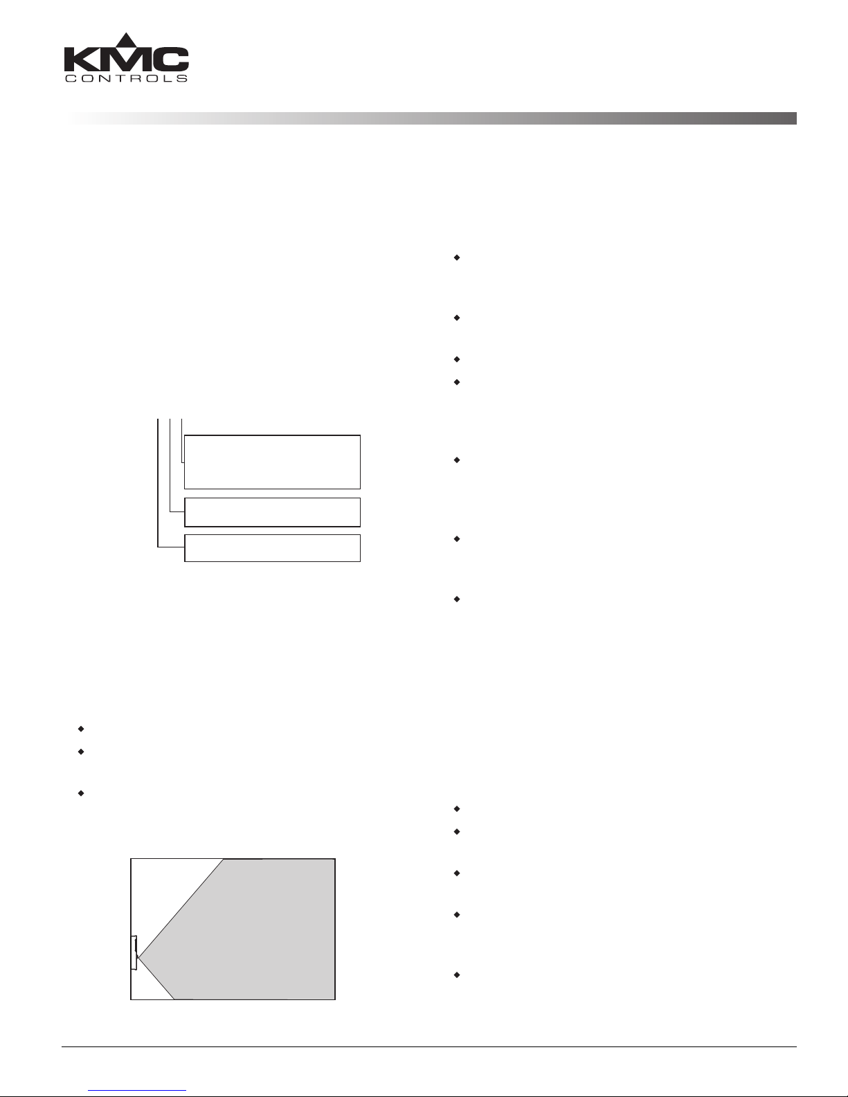
Planning for motion sensing
For models with a motion sensor mount the AppStat
on a wall that will have an unobstructed view of the
typical traffic in the coverage area. When choosing a
location, do not install the sensor in the following
areas.
Behind curtains or other obstructions
In locations that will expose it to sunlight or heat
sources
Near a heating or cooling inlet or outlet.
Illustration 2—Typical motion sensing coverage area
Illustration 1—Fan Coil Unit models
The effective detection range is approximately 10
meters or 33 feet. Factors that may reduce the range
include:
The difference between the surface temperature
of the object and the background temperature of
the room is too small.
Object movement in a direct line toward the
sensor.
Very slow or very fast object movement.
Obstructions as shown in the illustration Typical
motion sensing coverage area on page 1.
False detections may be triggered by:
The temperature inside the detection range
suddenly changes because of the entry of cold or
warm air from an air-conditioning or heating
unit.
The sensor being directly exposed to sunlight, an
incandescent light, or other source of far-infrared
rays.
Small animal movement.
Mounting the AppStat
For the most accurate performance, install the
AppStat on an inside wall where it can sense the
average room temperature. Avoid locations with
direct sunlight, heat sources, windows, air vents,
and air circulation or obstructions such as curtains,
furniture, etc.
The AppStat must not be:
Mounted on an exterior wall.
Mounted on or near an object with large a
thermal mass such as a concrete block wall.
Blocked from normal air circulation by
obstructions.
Exposed to heat sources such as lights,
computers, copiers, or coffee makers, or to direct
sunlight at any time of the day.
Exposed to drafts from windows, diffusers, or
returns.
AppStat For Fan Coil Units 1
Installation Guide
Page 2

Exposed to air flow through connecting conduits
A
5.12 in.
130 mm
3.50 in.
89 mm
Inputs and
network
Power and outputs
Turn clockwise to remove
from base.
Turn counterclockwise
until the screw engages
the base.
Caution
Remote Space Temp.
Water Source Temp.
Discharge Air Temp.
N.C. Fan Status
MS/TP
+B
A
RS
WST
GND
DAT
COM
FAN-L
FAN-M
FAN-H
R
BO4
BO5
GND
AO6
AO8
AO7
24VAC
or empty spaces behind walls.
For models with motion sensing, see the topic,
Planning for motion sensing.
Rough-in preparation
Complete rough-in wiring at each location before
mounting an AppStat. This includes the following
steps.
Install the supplied mounting base directly to a
wall, a vertical electrical box, or a box with a wall
plate kit.
Routing the connecting cable or cables from the
AppStat to the equipment it is controlling.
If required, install an appropriate wall plate kit.
Block leaks and airflow from conduits with
plumber’s putty or similar material.
If replacing an existing thermostat, label existing
wires for reference when removing the existing
thermostat.
Illustration 3—AppStat mounting base details
mounting base.
4.
Position the base with the embossed UP toward
the ceiling and fasten it directly to a vertical 2x4
inch electrical box. For horizontal boxes or 4x4
applications, use a wall plate kit. See Installation
accessories on page 4 for part numbers.
5.
Connect the wires for the AppStat to the
terminals in the mounting base.
6.
Place the top of the sensor over the top of the
mounting base and swing it down over the Allen
screw bracket. Be careful not to pinch any wiring.
7.
Turn the Allen screw counterclockwise until it
backs out of the mounting base and engages the
case.
To prevent mounting screw heads from
touching the circuit board in the
controller, use only the mounting
screws supplied by KMC Controls.
Using screws other than the type
supplied may damage the AppStat.
Installing the AppStat
To install the controller on a mounting base, do the
following:
1.
Turn the Allen screw in the base of the sensor
clockwise until it clears the case.
2.
Swing the AppStat away from the mounting base
to remove it.
3.
AppStat For Fan Coil Units 2
Route wiring for the AppStat through the
Connecting inputs
The inputs for the AppStat are configured for
specific functions and do not require set up in the
field. Not all inputs are required for every model or
application.
Illustration 4—FCUinputs
Remote space temperature sensor (optional)
Connect a 10kΩ, TypeII thermistor temperature
sensor to the remote space temperature (RS) input
and ground (GND) terminals. The input includes
Installation Guide
Page 3

the internal pull-up resistor. An STE-6011W10
Caution
0-10VDC
0-10VDC
0-10VDC
MS/TP
+B
A
RS
WST
GND
DAT
COM
FAN-L
FAN-M
FAN-H
R
BO4
BO5
GND
AO6
AO8
AO7
24VAC
24 VAC
24VAC
24VAC
24VAC
24VAC
24VAC
24 VAC
Class-2
Controls
transformer
MS/TP
+B
A
RS
WST
GND
DAT
COM
FAN-L
FAN-M
FAN-H
R
BO4
BO5
GND
AO6
AO8
AO7
24VAC
sensor is suitable for this application. Follow the
instructions supplied with the sensor for
installation.
When a remote space temperature input is
connected to the AppStat, the remote temperature is
used instead of the internal temperature sensor.
Fan status switch (optional)
Connect a Normally Closed Fan Status switch to the
Discharge Air Temperature (DAT) input and ground
(GND) terminals. The input includes the internal
pull-up resistor. A CSE-1102 differential pressure
switch is suitable for this application. Follow the
instructions supplied with the switch for
installation.
Water temperature sensor
Connect a 10kΩ, Type III thermistor temperature
probe to the water temperature (WST) input. The
input includes the internal pull-up resistor. An
STE-1455 sensor is suitable for this application.
Follow the instructions supplied with the sensor for
installation.
Note: The water temperature sensor is a required
input sensor for 2-pipe fancoil units.
Discharge air temperature
Connect a 10kΩ, Type III thermistor temperature
probe to the discharge air temperature (DAT) input.
The input includes the internal pull-up resistor. An
STE-1405 sensor is suitable for this application.
Follow the instructions supplied with the sensor for
installation.
Connecting outputs
The AppStat outputs are model dependent and are
configured for specific applications.
No field programming or set up is required or
possible.
Depending on model and application, the
AppStat outputs are designed for either 24
voltAC or 0-10 voltDC loads.
The outputs may represent analog or digital
signals.
AppStat For Fan Coil Units 3
Improperly connecting loads or
equipment to output terminals may
damage the equipment. Connect only
as shown in the following diagrams or
application drawings.
Illustration 5—FCU output terminals
Connecting power
The AppStat requires an external, 24 volt, AC power
source. Use the following guidelines when choosing
and wiring transformers.
Use only a Class-2 transformer of the
appropriate size to supply power.
KMC Controls recommends powering the
AppStat from a dedicated controls transformer.
Connect the transformer’s neutral lead to the
COM terminal.
Connect the AC phase lead to the 24VAC
terminal.
Power is applied to the controller when the
transformer is powered.
See Installation accessories on page 4 for a list of
transformers available from KMC Controls, Inc.
Illustration 6—Wiring for AppStat power
Installation Guide
Page 4

Maintenance
Remove dust as necessary from the holes in the top
and bottom. Clean the display with soft, damp cloth
and mild soap.
Specifications
AppStat specifications are subject to change without
notice.
Supply Voltage 24 volts AC (–15%, +20%),
50-60 Hz, 12 VA,
Class 2 only
Inputs 0–12 volts DC with internal 10kΩ
pull-up resistors
Relay outputs SPST, 24 volts, 1 amp AC or DC
Maximum for all relay outputs is
3 amps
Analog outputs Short protected 10mA 0–12 VDC
Environmental
limits
Regulatory UL 916 Energy Management
This device complies with part 15 of the FCC Rules.
Operation is subject to the following two conditions:
(1) This device may not cause harmful interference,
and (2) this device must accept any interference
received, including interference that may cause
undesired operation.
Operating 34 to 125° F (1.1 to
51.6° C)
Shipping –40 to 140° F
(–40 to 60° C)
Humidity 0 to 95% RH
(non-condensing)
Equipment
FCC Class B, Part 15, Subpart B
and complies with Canadian
ICES-003 Class B
Installation accessories
The following accessories are available from KMC
Controls, Inc.
XEE-6111-040 Single-hub 120 volt power
transformer
XEE-6112-040 Dual-hub 120 volt power
transformer
XEE-6311-075 120/240/277/480VAC, 24 VAC, 75 VA
transformer
HMO-10000W White mounting plate kit for retrofit
on horizontal boxes or 4 x 4 handy
boxes
Additional resources
The latest support files are always available on the
KMC Controls web site.
For detailed specifications, installation, operating ,
application, and system integration information, see
The Installation, Operation, and Application Guide
for AppStat.
For additional specifications information, see the
BAC-4000 AppStat Data Sheet.
Important Notices
The material in this document is for information
purposes only. The contents and the product it
describes are subject to change without notice. KMC
Controls, Inc. makes no representations or
warranties with respect to this document. In no
event shall KMC Controls, Inc. be liable for any
damages, direct or incidental, arising out of or
related to the use of this document.
KMC Controls, Inc.
P.O. Box 497
19476 Industrial Drive
New Paris, IN 46553
U.S.A.
TEL: 1.574.831.5250
FAX: 1.574.831.5252
E-mail: info@kmccontrols.com
AppStat For Fan Coil Units 4 919-019-01B
 Loading...