

KMB SMY-CA Operating Manual

The complete and most actual version of this manual is available online at http://www.KMB.cz/
Contents
KMB systems, s. r. o.
Dr. M. Hor´akov´e 559, 460 06 Liberec 7, Czech Republic
E-mail: kmb@kmb.cz, Web: www.kmb.cz
Operating Manual for
SMY-CA
version 2.0
6/2016
1 General Description 1
2 Operating the Meter 2
2.1 Safety requirements when using SMY-CA . . . . . . . . . . . . . . . . . . . . . . . . . . . . . . . 2
2.2 Instrument overload warning . . . . . . . . . . . . . . . . . . . . . . . . . . . . . . . . . . . . . . 2
2.3 Installation . . . . . . . . . . . . . . . . . . . . . . . . . . . . . . . . . . . . . . . . . . . . . . . . 2
2.3.1 Connection step by step . . . . . . . . . . . . . . . . . . . . . . . . . . . . . . . . . . . . . 3
2.3.2 Disconnection . . . . . . . . . . . . . . . . . . . . . . . . . . . . . . . . . . . . . . . . . . . 4
2.3.3 Communication peripherals . . . . . . . . . . . . . . . . . . . . . . . . . . . . . . . . . . . 5
2.4 Lock/unlock the instrument . . . . . . . . . . . . . . . . . . . . . . . . . . . . . . . . . . . . . . . 5
2.4.1 Locking the instrument . . . . . . . . . . . . . . . . . . . . . . . . . . . . . . . . . . . . . 5
2.4.2 Unlocking the instrument . . . . . . . . . . . . . . . . . . . . . . . . . . . . . . . . . . . . 5
2.5 Basic instrument setup . . . . . . . . . . . . . . . . . . . . . . . . . . . . . . . . . . . . . . . . . . 6
2.5.1 Installation type and options . . . . . . . . . . . . . . . . . . . . . . . . . . . . . . . . . . 6
2.5.2 Communication options . . . . . . . . . . . . . . . . . . . . . . . . . . . . . . . . . . . . . 7
2.5.3 Time and date options . . . . . . . . . . . . . . . . . . . . . . . . . . . . . . . . . . . . . . 7
2.6 Downloading data to PC . . . . . . . . . . . . . . . . . . . . . . . . . . . . . . . . . . . . . . . . . 8
2.7 Energy meter readings . . . . . . . . . . . . . . . . . . . . . . . . . . . . . . . . . . . . . . . . . . 8
3 Technical Specifications 9
3.1 Basic Parameters . . . . . . . . . . . . . . . . . . . . . . . . . . . . . . . . . . . . . . . . . . . . . 9
3.2 Measured Quantities . . . . . . . . . . . . . . . . . . . . . . . . . . . . . . . . . . . . . . . . . . . 11
4 Maintenance and Service 14
1 General Description
multifunctionalpanel meter
SMY 133
multifunctionalpanel meter
ETH5m
SMY-CA
XKK-1001
SMY-CU3
The portable power analyser SMY-CA is specially designed for monitoring of energy and power quality in
advanced power systems and smart grids. It uses standard USB port for local configuration and data acquisition
and also Ethernet for communication with remote control systems.
It is equipped with three voltage inputs and three current inputs for current sensors with X/333mV outputs.
Warning ! The X/333 mV, options is specially designed to be used only in combination with provided
external current sensors which are supported with the respective option.
SMY-CA is based on SMY 133 panel power meter and shares most of its features.
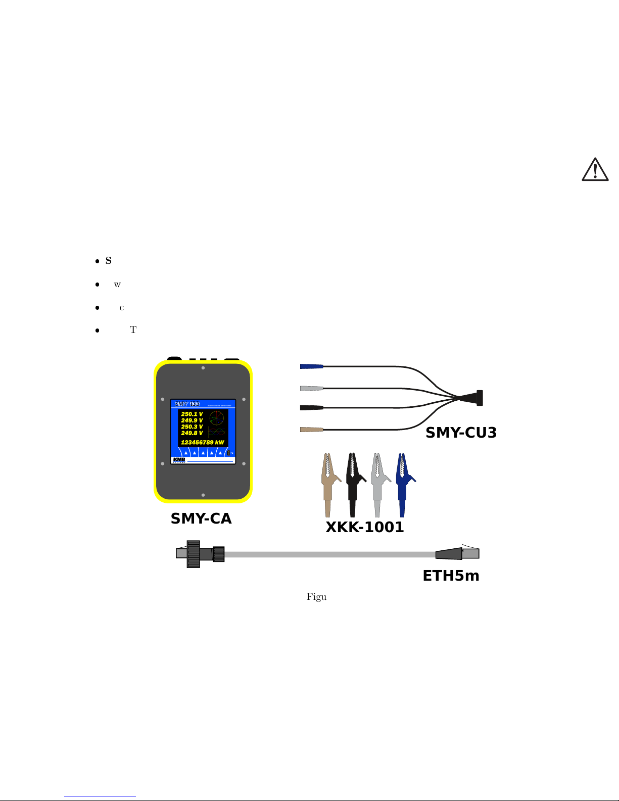
Basic set of SMY-CA contains following
SMY-CA power analyser
4 wire voltage probe SMY-CU3 with built-in fuses
4 pcs of croco-clips XKK-1001
5m UTP ethernet cable ETH5m with IP65 rated screw type connector from one side
There are also range of different optional current sensors available (see. Table 1)
Figure 1
1

Sensor Model Inom [A] d [mm] Description
CA-JRF MOI 333M-80 100
100 A 80 mm Flexible current sensor, max. 100A, diameter 80mm, 3pin IP65 bayonet locking connector
CA-JRF MOI 333M-80 300
300 A 80 mm Flexible current sensor, max. 300A, diameter 80mm, 3pin IP65 bayonet locking connector
CA-JRF MOI 333M-115 100
100 A 115 mm Flexible current sensor, max. 100A, diameter 115mm, 3pin IP65 bayonet locking connector
CA-JRF MOI 333M-115 300
300 A 115 mm Flexible current sensor, max. 300A, diameter 115mm, 3pin IP65 bayonet locking connector
CA-JRF MOI 333M-115 1000
1000 A 115 mm Flexible current sensor, max. 1000A, diameter 115mm, 3pin IP65 bayonet locking connector
CA-JRF MOI 333M-115 2500
2500 A 115 mm Flexible current sensor, max. 2500A, diameter 115mm, 3pin IP65 bayonet locking connector
Sensors with Inom above 2500A on request.
Table 1: Current sensor options
2 Operating the Meter
2.1 Safety requirements when using SMY-CA
Warning !: When working with the instrument it is necessary to perform all necessary measures for the
protection of persons and property against injury and electric shock.
The device must be operated by a person with all required qualifications for such work and this person
must know in detail the operation principles of the equipment listed in this description!
When the device is being connected to the parts which are under dangerous voltage it is necessary to comply
with all the necessary measures to protect users and equipment against injury with electrical shock.
Person, performing the installation or maintenance of the instrument must be equipped with and must use
personal protective clothing and tools.
If the analyzer is used in a manner not specified by the manufacturer, the protection provided by the
analyzer may be impaired.
If the analyzer or its accessories appear to be impaired or not functioning properly, do not use it and send
it in for repair.
2.2 Instrument overload warning
When connecting to the measured voltage using croco clips it is necessary to pay more attention to correct
connection of conductor N (neutral, blue).
Warning !: An incorrect connection of the conductor N to one of phase voltages causes built-in power
supply overload and serious damage of the instrument!!!
It is always strongly recommended to connect first the conductor N (blue) to the network neutral conductor.
Then check this connection properly and only then connect other wires to the voltages of phases L1, L2, L3.
2.3 Installation
The instrument can be used only in networks with maximum voltages not-exceeding its maximum available
power supply voltage (see technical specifications). For its operation, the instrument requires supply voltage
which is provided directly from measured voltage of phase L1. If current measurement is required too, use
appropriate current sensors with 333mV output.
2

2.3.1 Connection step by step
1. Attach selected power cable to the instrument U connector and fasten it by mild tightening of the cap nut.
2. Check that recording control switch is in OFF position (O).
3. Now we will connect measured voltages to the instrument using voltage cable. In case of connection with
croco clips wearing insulation gloves is strongly recommended while connecting the cable to the points
of measurement! Use croco clips or magnetic adapters. Firstly connect the N (neutral, blue) wire to
the neutral conductor of measured network; now, this connection should be properly checked to avoid
confusion with any of the phase conductors! Then, connect the phase wire L1 (brown) to the measured
phase conductor and by looking at the instrument display check if it has started running. Finally, connect
remaining wires L2 (black) and L3 (grey)
4. Now you can check the connection on the instrument’s display – phase voltage magnitudes should corre-
spond to reality and in the phasor diagram phase rotating sequence can be verified.
5. If you want to measure currents as well, appropriate current sensors must be installed. During this, wearing
the insulation gloves is strongly recommended again! Generally, the current sensors are interchangeable.
But for better orientation we recommend to respect their marking – connect the brown sensor to the L1
current input, the black one to the L2 input and the gray sensor to the L3 input. Correct polarity must
be observed while connecting current sensors. The arrow on the current sensor must show the direction
of the nominal power flow (from the power source to point of consumption). After locking up the sensor
lock, adjust the sensor position on measured conductor in order that the lock is as far of the conductor as
possible – in such position the measurement accuracy is the best. Then we again recommend to check the
sensors connection on the instrument’s display – for example using the phasor diagram.
6. Now, if not already set, we will configure ratio of CTs and other settings through display or using EN-
VIS.Daq software.
7. Now we can do final verifycation of the conncetion. On the display we can list measured values of voltage
and current. If we have also laptot we can use ENVIS.Daq to connect via USB or Ethernet to check live
data.
8. If connection and configuration is correct, we can start the recording. To do so, switch recording control
switch located on front panel to ON position (I). Since now, both the recording and the electricity meter
operation is unblocked and measured values start being registered into the instrument archives.
3

PE
N
230/400 V AC
50 / 60 Hz
VOLTAGE
3×230/400V
ETHERNET
CURRENT
I1
I2
I3
multifunctionalpanel meter
multifunctionalpanel meter
Figure 2: Typicall connection of SMY-CA in LV network
2.3.2 Disconnection
After recording of measurement for the desired period of time has been completed, it is necessary to disconnect the
instrument from the points of measurement and transfer the data recorded to a computer. When disconnecting,
the same precautions must be observed as those for connecting it and carry out all the steps in reversed order.
1. Turn off recording by switching recording control button to OFF position (O).
4
 Loading...