

KMB SML 133 Series, SML 133 230 X/5A, SML 133 X/100mA, SML 133 X/333mV, SML 133 X/5A Operating Manual
KMB systems, s.r.o.
Dr. M. Horákové 559, 460 06 Liberec 7, Czech Republic
tel. +420 485 130 314, fax +420 482 736 896
email : kmb@kmb.cz, internet : www.kmb.cz
SML 133
Multifunctional Meter
Operating Manual
Firmware 2.0.32
The instrument measures line and phase voltages, currents, active, reactive and apparent powers,
power factors, THD and harmonics of voltages and currents, as well as frequency in single-phase and
three-phase low, medium and high voltage power systems.
Built-in electricity meter measures electric energy in four quadrants (both active and reactive
energies), as well maximum active power demand.
The instrument further allows informative measurement of temperatures within a switchboard cabinet
using an inbuilt temperature sensor.
Besides actual values, average values during preset time window are evaluated too. Maximum and
minimum values of them are registered.
The instrument feature three voltage and three fully isolated current measuring inputs.
Nominal range of the voltage inputs can be in range from 57.7/100 up to 400/690 VAC,optionally.
The current inputs are designed for indirect measurement only - they must be connected via external
current transformers. The models with current-type inputs are available as either the „X/5A“, i.e. with 5
AAC nominal range (for standard CTs), or the „X/100mA“ with nominal range of 0.1 AAC. The „X/333mV“
models are determined either for CTs with output nominal voltage of 333 millivolts or for flexible
current sensors (Rogowski coils) with embedded integrator and appropriate output voltage. Such
models are equipped with auxiliary power supply of 5V for the sensors.
The instrument can be optionally equipped with two relays with programmable function or solid-state
outputs that can be used as electricity meter impulse outputs and one digital input for general state
monitoring.
Power supply of standard instrument models has universal range 85 ÷ 275 VAC or 80 ÷ 350 V
DC.
Optional power supply range is 12 ÷ 48 V
DC.
The instruments can be equipped with an RS 485, Ethernet or M-Bus communication interface. Then
the ENVIS software allows remotely viewing data measured. For custom design systems, the Modbus
communication protocol can be used too.
5 / 2016

SML133 Operating Manual
1. Putting in Operation
1.1 Instrument Connection
1.1.1 Physical
The SML 133 instrument is built in a plastic box to be installed in a distribution board panel. The
instrument’s position must be fixed with locks.
Natural air circulation should be provided inside the distribution board cabinet, and in the instrument’s
neighbourhood, especially underneath the instrument, no other instrumentation that is source of heat
should be installed or the temperature value measured may be false.
1.1.2 Power Supply
The supply voltage (in range according technical specifications) connects to terminals AV1 (No. 9) and
AV2 (10) via a disconnecting device (switch – see wiring diagram). It must be located at the
instrument’s proximity and easily accessible by the operator. The disconnecting device must be
marked as such. A circuit breaker for nominal current of 1 amp makes a suitable disconnecting device,
its function and working positions, however, must be clearly marked.
In case of DC supply voltage the polarity of connection is generally free, but for maximum
electromagnetic compatibility the grounded pole should be connected to the terminal AV2.
1.1.3 Measured Voltages
The phase voltages measured are connected to terminals L1 (12), L2 (13), L3 (14), the common
terminal to connect to the neutral wire is identified as N (11; it stays free at delta- (3-D) and Aron- (A)
connections). It is suitable to protect the voltage lines measured for example with 1A fuses. Measured
voltages can also be connected via instrument voltage transformers.
A connection cable maximum cross section area is 2.5 mm2.
SML 133 U 400 X/5A Instrument Rear Panel
1.1.4 Measured Currents
The instruments are designed for indirect current measurement via external CTs only. Proper current
signal polarity (S1 & S2 terminals) must be observed. You can check the polarity by the sign of phase
active powers on the instrument display (in case of energy transfer direction is known, of course).
In the P.01 parameter (see below), set the CT-ratio.
The I2 terminals stay free in case of the Aron (A) connection.
2

SML133 Operating Manual
1.1.4.1 Current Type Current Inputs Instruments ( Models „X/5A“, „X/100mA“ )
The current signals from 5A or 1A (or 0.1A for the „X/100mA“ models) instrument current transformers
must be connected to the terminal pairs I11, I12, I21, I22, I31, I32 (No. 1 ÷ 6).
A connection cable maximum cross section area is 2.5 mm2.
1.1.4.2 Voltage Type Current Inputs Instruments ( Models „X/333mV“ )
The instruments are equipped with separate connectors for particular measuring current input. Each
connector has three terminals. Function of the terminals is described in following table :
“X/333mV“ Models Current Inputs Connection
terminal No. signal
62 SI1 … signal corresponding to I1 current (in phase L1), CT terminal “S1”
65 SI2 … I2-S1 (phase L2)
68 SI3 … I3-S1 (phase L3)
63, 66, 69 SG …common pole of the I1 ÷I3 signals (CT terminals “S2”) and negative pole of the
5V built-in auxiliary power supply for current sensors (the terminals are
interconnected)
61, 64, 67 SP... positive pole of the 5V built-in auxiliary power supply for current sensors (the
terminals are interconnected)
The instruments are designed for cooperation with current transformers with output nominal voltage of
333 millivolts. They can be also used with flexible current sensors (Rogowski coils) with embedded
integrator of appropriate voltage output signal.
The CTs must be connected with two-wire twisted cable of 1.5 mm2 maximum cross section area.
Again, proper current signal polarity (CT secondary terminals S1, S2) must be observed.
Maximum length of the cable is 3 metres !
The flexible current sensors with embedded integrator usually require a power supply. For such
purpose the instruments are equipped with auxiliary power supply 5V. Maximum load of each sensor
connected is 20 mA.
Connection of standard CTs with 5A or 1A nominal output current to the „X/333mV“
instruments s forbidden !!! Otherwise the instrument can be damaged !!!
1.2 Basic Operation
On connecting power supply the display shows all of the segments, then gradually screens
with the instrument type and setting of basic parameters :
1. line 1 : 1 3 3 - instrument type number
line 2 : 5 A - current input type
line 3 : r I- digital output type : relay (r), pulse (I), or none (n)
2. when connection of voltage via voltage transformers set (otherwise the screen is skipped) :
line 1 : U t - voltage transformer connected identification
line 2 : nominal primary voltage [kV]
line 3 : nominal secondary voltage [kV]
3
SML133 Operating Manual
3. line 1 : C t - current transformer/range specification
line 2 : nominal primary current [A]
line 3 : nominal secondary current [A]
4. line 1 : F U - nominal frequency and voltage
line 2 : nominal frequency
line 3 : nominal voltage
Then the instrument starts display actual measured values. Simultaneously, if the instrument has a
communication line, the values can be read via the communication link using a PC.
1.2.1 Setup
At this moment it is necessary to set instrument parameters that are essential for proper instrument
measurement :
• CT ratio – parameter 01 (and its multiplier, optionally)
• type of connection – parameter 02 (wye, delta, Aron)
• mode of connection – parameter 04 (direct or via VT, VT ratio and multiplier, optionally)
• nominal frequency f
NOM
and nominal voltage U
NOM
– double parameter 05
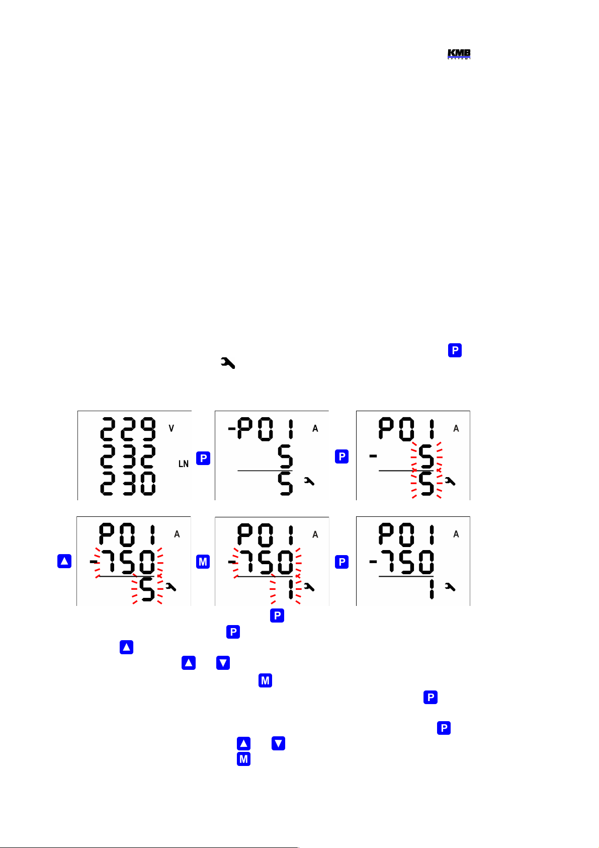
Usually, it is only necessary to adjust the CT ratio. Next example shows how to do it :
Assuming that the ratio of used CTs is 750/1 A. First off all, it is necessary to switch display from
measured data branch (the ULN screen on the example below) to the parameter branch with the
button. The branch is indicated with the symbol . Parameter 01 appears – this parameter is the
CT ratio and its default value is 5/5 A.
CT Ratio Change Procedure Example
Now enter editing mode by pressing and holding the until the value gets flashing.
As soon as the value flashes, release the . Now you can change it. Increase primary value by
pressing of the . If you keep it pressed two-speed autorepeat helps to reach target value quickly.
Then use multiple pressing of and for fine setup.
To change the secondary value, simply press the . The button toggles between 5 and 1.
Target CT value is prepared now and we can leave the edit mode with (short) pressing the . The
value is stored into the instrument memory and the flashing stops.
Now return to so called main parameter branch (see description below) with next pressing the and
then you can scroll to other parameters with and and edit them in a similar way or you can
return to the measured data branch with the .
4
long
multi
ple

SML133 Operating Manual
The summary of all instrument parameters is stated in the table below. Their description is stated in
following chapters.
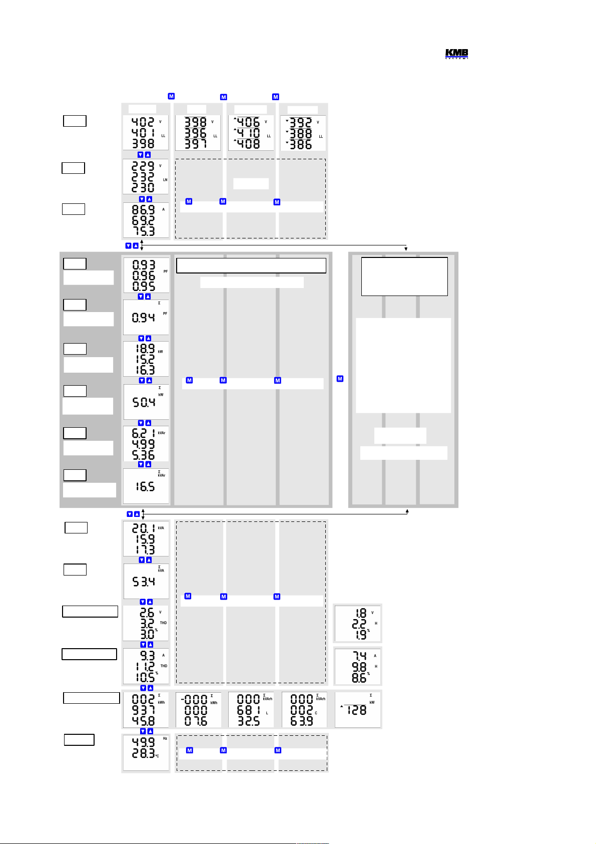
1.2.2 Measured Data
The instrument starts display actual measured values on power-up. The screen that was selected
before the last powerdown is displayed. You can navigate through all of measured and evaluated
values with , and buttons as shown on the Measured Data Navigation Chart below.
If phase values displayed, individual L1 / L2 / L3 - phase value is shown in the line 1 / 2 / 3. If a threephase value is displayed, it is shown in the line 2 and the Σ symbol appears.
The quantities' meaning and evaluation formulas can be found in the appropriate chapter further
below.
Most of data are arranged in four columns :
• Actual …. actual values, refreshed each 3 measurement cycles (30/36 mains cycles)
• Avg …...... average values per appropriate averaging period (see below)
• AvgMax ... maximum of the avg-value reached since the last clearing
• AvgMin …. minimum of the avg-value reached since the last clearing
You can scroll inside a column down and up with the and keys and move horizontally from a
column to the next right one cyclically with the key.
Exception : Only actual values of harmonics and electrical energy are available. These values are
arranged in different way – see further below.
If any of actual values of voltages or currents flashes, corresponding voltage / current
exceeds measuring range of the instrument !
1.2.2.1 Average Values
Average values are processed according set averaging method and length of averaging window
(individually for “U/I”-group and “P/Q/S”-group of quantities). Maximum and minimum values of them
are registered into the instrument's memory. The maximums are displayed in the “AvgMax” column
and they are identified with the ▲symbol in the front of the value. Analogically, the minimums in the
“AvgMin” column are identified with the ▼symbol.
Neither maximum nor minimum of cosφ values are evaluated due to special character of the
quantity. Similarly, these extreme values are not evaluated at harmonics.
You can clear the “AvgMax”/“AvgMin” values. All of the maximums/minimums of appropriate quantity
group are cleared simultaneously. To do it, follow next :
• navigate on corresponding AvgMax or AvgMin value
• press the key until the value starts flashing
• with the or key, choose the C L r option
• then confirm by pressing the
The appropriate group ( U/I or P/Q/S ) of average maxs/mins is affected by single clearing
only ! Each group must be cleared individually.
If the instrument is locked, the clearing is not possible.
5
SML133 Operating Manual
SML133 Measured Data Branch Navigation Chart
6
line-to-line
voltages
active phase
powers
ULL
ULN
I
phase currents
PF
3-phase power
factor
ΣPF
phase power
factors
P
ΣP
active 3-phase
power
Q
reactive phase
powers
ΣQ
reactive 3-phase
power
S
apparent phase
powers
ΣS
apparent 3-phase
power
TDHU, Uh
TDHI, Ih
3-phase energies,
3-phase average
active power max.
ΣE,ΣPavgmaxE
f, T
frequency,
temperature
current total harm.
distortion,
current harmonics
Actual
Avg
AvgMax
AvgMin
Full Spectrum Values Branch
PF, ΣPF, P, ΣP, Q, ΣQ
Fundamental
Harmonic Values
Branch
cos φ / tanφ /φ
Σcos φ / Σtanφ / Σφ
(act. values only)
Pfh
ΣPfh
Qfh
ΣQfh
see the next
figure for details
(fundamental harmonic branch
indicated with the “H” character)
similarly
→ Avg → AvgMax → AvgMin
→ Avg → AvgMax → AvgMin
→ Avg → AvgMax → AvgMin
→ Avg → AvgMax → AvgMin
Electricity Meter Row :
1. Active – Import
2. Active – Export (-)
3. Reactive – Inductive (L)
4. Reactive – Capacitive (C)
5. ΣpavgmaxE
(Default „8E+Pmax“ format.
For „6E“ optional electricity
meter format see next
figure.)
Voltage THD & Harmonics
Row
Odd Actual Harmonics Only,
up to 25th Order
Current THD & Harmonics
Row
Odd Actual Harmonics Only,
up to 25th Order
→
→
→
→
voltage total harm.
distortion,
voltage harmonics
line-to-neutral
voltages
SML133 Operating Manual
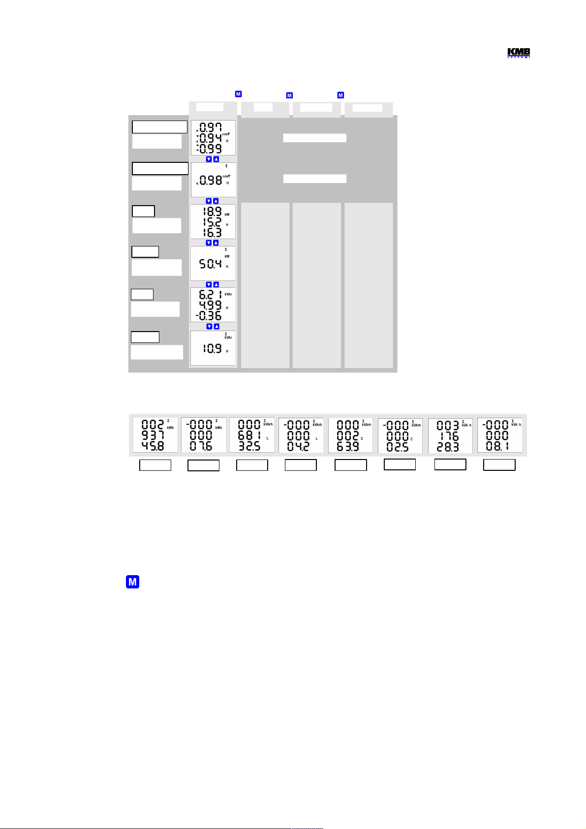
SML133 Fundamental Harmonic Values Branch
Optional “8E” Electricity Meter Display Format
1.2.2.2 Full Spectrum Values P/Q/PF & Fundamental Harmonic Values Pfh/Qfh/cos φ
As standard, active and reactive powers (and therefore power factor) are evaluated from full spectrum
of harmonic components of both voltage and current.
Sometimes (for example for power factor compensation system checking), it is useful to know
fundamental harmonic part of these quantities too. Such quantities are marked Pfh, Qfh, cos φ.
As you can see on the navigation chart you can navigate from the full spectrum values branch with the
key further right into the fundamental harmonic values branch and vice versa. To distinguish
actual displayed branch, the H symbol is displayed for the fundamental harmonic branch.
Exception : Actual values only of fundamental harmonic power factor – the cos φ – are evaluated (no
average values available). Next, this fundamental harmonic power factor can be expressed not only
as cos φ, but as tan φ or φ too, depending on setting of parameter 09.
1.2.2.3 Fundamental Harmonic Power Factor Formats cosφ/tanφ/φ
The fundamental harmonic power factor can be expressed not only as cos φ, but as tan φ or φ too,
depending on setting of parameter 09.
For outright specification of the quadrant, the power factor of the fundamental harmonic component is
accompanied with two attributes :
• a sign ( + or - ), which indicates polarity of appropriate active power
7
Avg
AvgMax
AvgMin
→
→
→
ΣEP+
ΣEP-
ΣEQL+
ΣEQL- ΣEQC+
ΣEQC-
ΣES+
ΣES-
active phase
powers
cos (tan,φ)
3-phase power
factor
Σcos(tan,φ)
phase power
factors
Pfh
ΣPfh
active 3-phase
power
Qfh
ΣQfh
reactive 3-phase
power
reactive phase
powers
( actual values only )
( actual values only )
Actual

SML133 Operating Manual
• a symbol or , which indicates the power factor character
For detailed information see chapter Power, Power Factor and Unbalance Evaluation Method below.
At the following figures there are examples of three-phase fundamental power factor presentations :
• the left figure : Σcos φ = 0.98 inductive (choke symbol displayed). Furthermore, active three
phase power is being negative, therefore the leading “minus”-sign ( and the symbol
displayed )
• the middle figure : Σtan φ = 0.20 inductive. Active three phase power is positive.
• the right figure : Σφ = 8 degrees inductive. Active three phase power is positive.
On the figure on the left, there is phase cos φ values example :
• cos φ1 = 0.97 inductive. L1-phase active power is currently
negative (because of leading “minus”-sign)
• cos φ2 = 0.94 inductive ( L2-phase active power currently
positive )
• cos φ3 = 0.99 capacitive ( L3-phase active power currently
positive )
1.2.2.4 THDs and Harmonic Components
You can check actual values of both voltage and current THDs and harmonic components in
appropriate rows (see the Measured Data Navigation Chart ).
When you scroll to one of this rows, THD values of all measured phases are displayed as default.
Symbols THD - V - LN or THD - A indicate phase voltage or current THD values, respectively.
With the key you can switch to harmonic components. The symbol H appears, indicating harmonic
components (of voltage or current). Symbol % means that the values are expressed in percent of
fundamental harmonic component. Order of harmonics just displayed flashes periodically in the
display middle line – for example, string H03 means 3rd harmonics.
By repetitive pressing of the key you can check other harmonics. Although the instrument
evaluates all of the harmonic components up to 50th order internally, only odd components to 25
th
order can be viewed of its display (full spectrum od the harmonics is available via communication
interface only).
1.2.2.5 Electricity Meter
Electricity meter comprises three-phase energy data and maximum tree-phase active power demand
value. The values are situated in particular row.
Depending on the parameter 08 setup, two electricity meter display modes can be chosen :
• “4E+Pmax” mode (default)
• “8E” mode
8
Fundamental Harmonic Power Factor Formats
Fundamental Harmonic
Power Factor Sign &
Character
SML133 Operating Manual
1.2.2.5.1 “4E+Pmax” Display Mode
In this mode, first four windows contain three-phase energies of four-quadrants :
• ΣEP+ … three-phase imported active energy, indicated with Σ - kWh (or MWh or kMWh =
GWh)
• ΣEP- … three-phase exported active energy, indicated with Σ - kWh and preceeding ― sign
• ΣEQL … three-phase inductive reactive energy, indicated with Σ - kVArh – L
• ΣEQC … three-phase capacitive reactive energy, indicated with Σ - kVArh - C
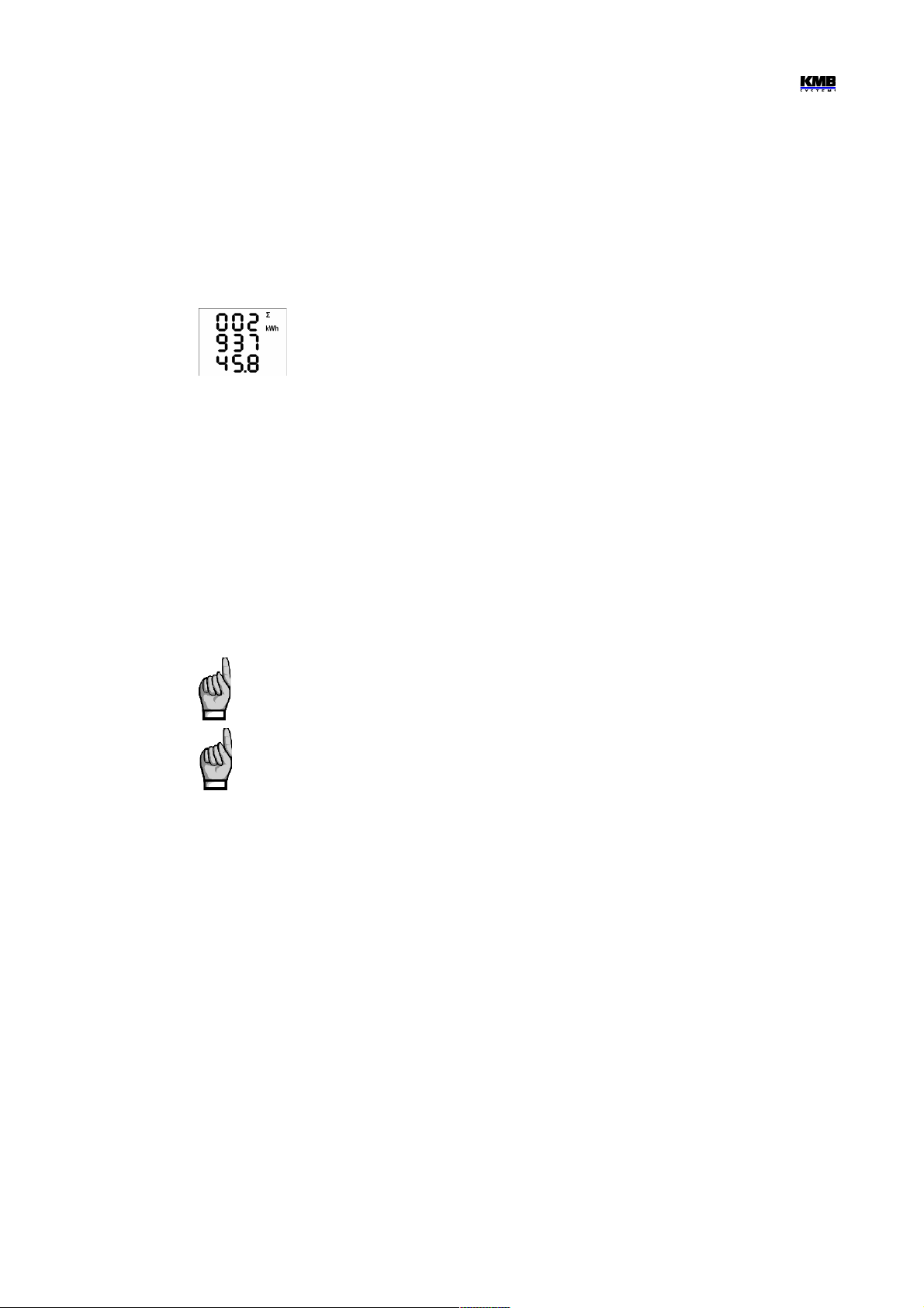
Each value occupies all of three display lines, 8 digits before the decimal point and
one after it. For the exaple at left, ΣEP+ = 293745.8 kWh.
The values are registered since the last clearing. To clear the energies, display any of them and then
follow the same procedure as for max/min average values. All of the energies are cleared
simultaneously ant start to count from zero again.
In the 5th window there is
• ΣPavgmaxE … maximum of three-phase average active power (power demand), indicated with Σ
- kW - ▲and bar over the value
The value contains maximum of three-phase average active power since the last clearing. Averaging
method and averaging period for this value can be set regardless of the method of standard average
values, described above. The quantity is marked with the “E” letter to distinguish from the standard
maximum average quantities.
Similarly as the energies, the value can be cleared independently.
If the instrument is locked, clearing is not possible.
If the instrument is equipped with a communication interface, the values can be cleared
remotely.
1.2.2.5.2 “8E” Display Mode
In this mode, reactive energies registered separately depending on actual three-phase active power
(ΣP) sign are displayed (such format can be convenient for renewable sources monitoring, for
example) :
• ΣEP+ … three-phase imported active energy, indicated with Σ - kWh (or MWh or kMWh =
GWh)
• ΣEP- … three-phase exported active energy, indicated with Σ - kWh and preceeding ― sign
• ΣEQL+ … three-phase inductive reactive energy registered during the ΣEP value was positive
(import); indicated with Σ - kVArh – L
• ΣEQL- … three-phase inductive reactive energy registered during the ΣEP value was negative
(export); indicated with Σ - kVArh – L and preceeding ― sign
• ΣEQC+ … three-phase capacitive reactive energy registered during the ΣEP value was
positive; indicated with Σ - kVArh – C
• ΣEQC- … three-phase capacitive reactive energy registered during the ΣEP value was
negative; indicated with Σ - kVArh – C and preceeding ― sign
Furthermore, energies in VAh are available too :
9
SML133 Operating Manual
• ΣES+ … three-phase apparent energy registered during the ΣEP value was positive; indicated
with Σ - kVAh
• ΣES- … three-phase apparent energy registered during the ΣEP value was negative; indicated
with Σ - kVAh and preceeding ― sign
The three-phase active power demand ΣPavgmaxE is not displayed in this mode.
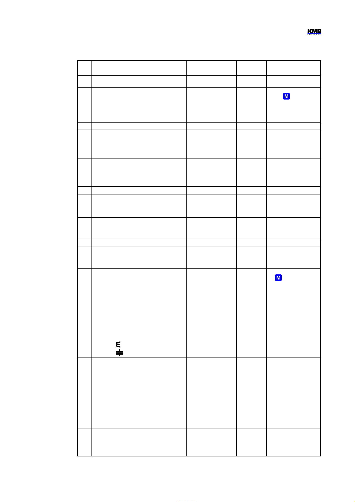
1.2.3 Instrument State Symbols
Except of measured data, the instrument indicates following states with dedicated symbols :
• …........ Export of three-phase active power. Displayed when the ΣP value is negative.
• / … A1(top) and A2 (bottom) alarm lights off / on. See output setup below.
• …......... I1 digital input state is active.
• …......... Instrument parameters are displayed.
1.2.4 Instrument Parameters
For proper operation in particular conditions, the instrument must be set. The instrument setup is
determined using parameters, for example the current transformer [CT] conversion, type of measured
voltage connection (direct connection or via a voltage transformer [VT] and its ratio), and connection
configuration (wye / delta / Aron). Overview of all the parameters is listed in the table below.
To check or edit the parameters, press the key. As default, parameter group 01 is displayed and
symbol (wrench) indicates, that setup data are displayed now.
The parameters are arranged in groups, numbered from 00 up. The number of group is displayed in
the first line in format - P. n n (with preceding dash). You can browse through the parameter groups
with the or keys.
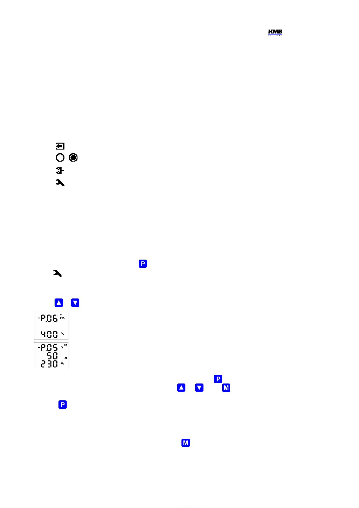
If one parameter only in the group, its value is in the bottom line as shown at the
example (nominal power 400 kVA).
If two parameters in the group, usually the first of them is displayed in the 2nd line and
the second in the 3rd line ( nominal frequency 50 Hz and nominal voltage 230 V).
To edit a particular parameter, scroll to its group. Then press and hold the until the value gets
flashing. Now release the key and set target value with the or , or the key for some of
parameters. You can use autorepeat function by keeping one of the arrow keys pressed too. Finally,
press the and the value is stored into the memory.
If more parameters in the group, the first one is chosen when entering editing mode for the first time. If
you want to modify the second parameter only, simply cancel editing of the first parameter without any
change and reenter the editing again – now the second parameter is chosen.
To return back to measured values display, simply press the key.
10
SML133 Operating Manual
SML 133 Instrument Parameters
# parameter group range default comment
00 lock LOC / OPN OPN
see Instrument Setup
Locking / Unlocking
01 CT – ratio, multiplier
screen 1 : row 2 : nominal primary current
row 3 : nom. secondary current
(for models “X/100mA”,“X/333mV” fixed)
screen 2 : MUL – current multiplier
primary : 1A ÷ 10 kA
sec. : 5A / 1A (0.1A)
(0.1 A, 0.333 V)
0.001 ÷ 999
5 / 5 A
1
secondary current selection
with the key
par. placed in side branch
if the current multiplier
different from 1 the ▲/
▼flashes
02 connection type 3Y / 3D / 3A 3Y
04 conn. mode: direct (---) or VT–ratio, mult.
screen 1 : row 2 : primary U [ kV ]
row 3 : secondary U [ kV ]
screen 2 : MUL – voltage multiplier
0.001 ÷ 65 kV
0.001 ÷ 0.999 kV
0.001 ÷ 999
direct
(- - -)
1
parameters placed in side
branch
if the voltage multiplier
different from 1 the ▲/
▼flashes
05 fNOM, UNOM
row 2 : fNOM [ Hz ]
row 3 : UNOM [ V / kV ]
50 / 60 Hz
50 V ÷ 1MV
50
230
UNOM specification
depending on connection
mode :
- direct : line-to-neutral
- via VT : line-to-line
06 ΣPNOM [ kVA / MVA ] 1 kVA ÷ 999 MVA
-
07 averaging period
row 2 : for U/I group
row 3 : for P/Q/S group
0.01 ÷ 60
(1 sec÷ 60 mins) 1 min
15 min
floating window type
averaging method applied
as default; thermal method
indicated with symbol ▲
08 avg period for ΣPavgmaxE,, El-meter d. mode
line 2 : averaging period for ΣPavgmaxE,
line 3 : Electricity meter display mode
0.01 ÷ 60
(1 sec÷ 60 mins)
“4E+Pmax” / “8E”
15 min
“4E+ Pmax”
floating window type
averaging method applied
09 fund. harmonic PF display format cos / tan / fi cos
10 backlight AUT / ON ON
AUT-mode : the backlight is
switched off automatically
after app. 5 mins if no key is
pressed
11 output setup
row 2 : output O1
row 3 : output O2
standard type : “-O-”
pulse type : pulses / kWh(kvarh)
control energy symbol :
• none … ΣEP+
• - … ΣEP-
• … ΣEQL
• … ΣEQC
“ - - -” = off
“-O-” = standard
output
0.001 ÷ 999000 =
pulse output
- - -
( off )
control energy selection with
the key
Standard type output can be
set via communication line
only, not from instrument
panel. Symbol ▲indicates
different setup of the alarm
light A1 from the O1 and the
A2 from the O2
If pulse type output set from
instrument panel, the A1
and the A2 alarm lights are
set identically as the O1 and
the O2, respectively.
15
(16)
communication interface 1 (and 2, opt.)
for RS-485 / M-Bus :
screen 1: row 2 : address
row 3 : rate [ kBd ]
screen 2: Prt (protocol) – databits & parity
for Ethernet:
screen 1 : DHCP
screen 2÷5 : IP1÷ IP4 (IP)
screen 6÷9 : MA1÷ MA4 (Subnet Mask)
screen 10÷13 : Gt1÷ Gt4 (Gateway)
1 ÷ 255
2.4 ÷ 460
8 / 9-n / 9-E / 9-0
ON / OFF
0 ÷ 255
0 ÷ 255
0 ÷ 255
1
9.6
8
OFF
10.0.0.1
255.255.255.0
10.0.0.138
parameters placed in side
branch
19 instrument status (read only)
row 2 : failure specification
row 3 : serial no. & instr. version (scroll)
0 ÷ 255
-
0
-
r. 2 : 0 = failure-free
r. 3 : S...serial no.
F... firmware version
b...bootloader version
H...hardware version
11
SML133 Operating Manual
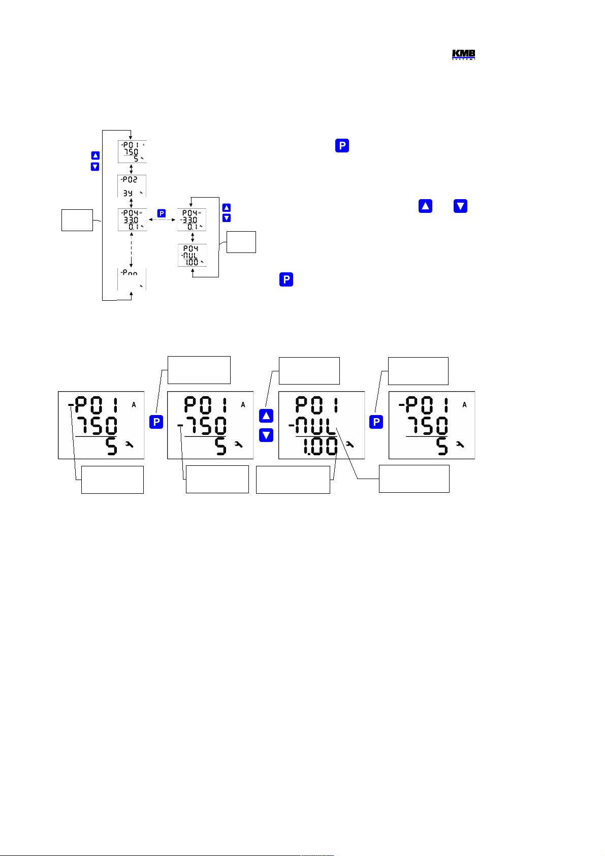
1.2.4.1 Main and Side Branch
For better orientation, some of parameters
(parameter group No. 01, 04, 15) are placed in
so called side branches. To enter into a side
branch, push . The dash in the front of the
parameter number skips down to the second
row indicating the side branch position.
Now you can list through parameters of chosen
group of parameters only with the and
keys. Usually, there is name or mark of a
parameter in the second line and the
parameter value in the third line.
To return back into the main branch push the
.
1.2.5 Instrument Setup Locking / Unlocking
When shipped, parameter editing is unlocked, that means :
• all of the parameters can be edited
• standard average maximums / minimums, electricity meter energies ΣEP+, ΣEP-, etc., and
electricity meter maximum power demand ΣPavgmaxE can be cleared
After being put in operation, such operations can be locked (=disabled) to protect the instrument
against unauthorized changes. Then operator can only check measured values and parameters, but
cannot change anything, excluding special parameter No. 00, that serves as the instrument lock. It
has one of two values :
L O C ....... instrument is locked
O p n ....... instrument is unlocked (open)
If the instrument is locked, you can unlock it using the following procedure, which is similar to editing
of other parameters:
12
main branch
indicator
side branch
indicator
enter into
side branch
side branch
listing
return into
main branch
next side branch
parameter
parameter
name (mark)
Main
Branch
Side
Branch
Arrangement of Parameters in Branches
Main and Side Branch Navigation

SML133 Operating Manual
1. Press the key and scroll to parameter group 00 with arrow keys – value L O C is
displayed.
2. Press the and hold it down until the value is replaced with flashing number between
0 0 0 and 9 9 9. As an example, you can imagine flashing 3 4 5 is displayed.
3. Press the following sequence: , , , . The value changes gradually to
3 4 4, 3 4 5, 3 4 6, 3 4 5, so the same value is shown at the end as at the
beginning.
4. Press the . The flashing number is replaced with O P n, indicating unlocked state.
The digit shown while entering the unlocking keypress sequence is random and it is not important for
correct unlocking (it is there only to confuse). Only the sequence of keys pressed is important and
must be followed exactly.
The instrument can be locked in a way analogous to unlocking but it is necessary to press any
keypress sequence that is different from the unlocking sequence noted above.
13

SML133 Operating Manual
2. Detailed Operation Description
2.1 Current and Voltage Multiplier
To get better precision when using overweighted CTs, you can apply more windings of measured wire
through the transformer. Then you must set so called multiplier. The current multiplier parameter is
placed in side branch of the P.01 parameter group and it is marked as “MUL”. For example, for 2
windings applied, set the multiplier to 1/2 = 0.5 .
For standard connection with 1 winding, the multiplier must be set to 1.
Similarly, the voltage multiplier can be set too (P.04 parameter group).
If the multiplier is set different from 1 the CT-ratio (or the VT-ratio) is
displayed with leading flashing arrow or , depending on the
multiplier value is higher or lower than 1.
At direct voltage connection mode (without VT), the voltage multiplier is not used and it value is not
displayed.
2.2 Method of Measurement
The measurement consists of three processes being performed continuously and simultaneously:
frequency measuring, sampling of voltage and current signals and evaluation of the quantities from
the sampled signals.
2.2.1 Voltage Fundamental Frequency Measurement Method
The voltage fundamental frequency is measured at the U1 voltage signal. It is measured continuously
and evaluated every 10 seconds.
The fundamental frequency output is the ratio of the number of integral mains cycles counted during
the 10 second time clock interval, divided by the cumulative duration of the integer cycles.
If value of frequency is out of measuring range, such state is indicated with flashing symbol Hz.
2.2.2 Voltage and Current Measurement Method
Both voltage and current signals are evaluated continuously as required by IEC 61000-4-30, ed. 2
standard. The unitary evaluation interval, a measurement cycle, is a ten / twelve ( value behind slash
is valid for f
NOM
= 60 Hz ) mains cycles long period ( i.e. 200 ms at frequency equal to preset f
NOM
),
which is used as a base for all other calculations.
The sampling of all voltage and current signals is executed together with the frequency of 128 / 96
samples per mains cycle. The sampling rate is adjusted according to the frequency measured on any
of the voltage inputs U1, U2, U3. If the measured frequency is in measurable range at least on one of
these inputs, then this value is used for subsequent signal sampling. If the measured frequency is out
of this range, the preset frequency value ( f
NOM
) is used and measured values may be incorrect.
Effective values of voltages and currents are calculated from sampled signals over the measurement
cycle using formulas (examples for phase No. 1) :
Phase voltage (effective value) :
∑
=
=
n
i
Ui
U
n
1
1
1
2
1
Line voltage (effective value) :
∑
=
−
=
n
i
UiUi
U
n
1
21
12
)(
2
1
14
 Loading...