

KMB NOVAR-1114, NOVAR-1414, NOVAR-1206, NOVAR-1214, NOVAR-1 Series Operating Manual
...
KMB systems, s.r.o.
Dr. M. Horákové 559, 460 06 Liberec 7, Czech Republic
tel. +420 485 130 314, fax +420 482 736 896
email : kmb@kmb.cz, internet : www.kmbsystems.eu
6/2014
Power Factor Controllers
NOVAR-1106 / 1114 / 1206 / 1214 / 1414
NOVAR-1xxx / S400
NOVAR-1005 / 1007 / 1005D / 1007D
NOVAR-1312, NOVAR-1312-3
Firmware v. 1.7 / 1.2 ( N1312 )
Operating Manual

Novar 1xxx KMB systems
2
LIST OF CONTENTS
1. DESCRIPTION.................................................................. 5
1.1 Manual Structure...................................................................................................................................5
1.2 Novar1106/1114/1206/1214 Basic Functions .....................................................................................5
1.3 Novar Controller Version “/S400”........................................................................................................6
1.4 Novar-1005 / 1007 / 1005D / 1007D.......................................................................................................6
1.5 Novar1312, Novar1312-3.......................................................................................................................6
1.6 Novar1414..............................................................................................................................................7
1.7 History of Firmware Versions ..............................................................................................................7
1.8 Front Panel ............................................................................................................................................8
1.9 Numeric Display....................................................................................................................................8
1.9.1 Novar 11xx / 12xx / 13xx Controllers..............................................................................................8
1.9.1.1 Instantaneous Measurement Values .........................................................................................8
1.9.1.2 Main Branch...............................................................................................................................8
1.9.1.2.1 COS Branch.......................................................................................................................10
1.9.1.2.2 A Branch ............................................................................................................................11
1.9.1.2.3 V Branch ............................................................................................................................12
1.9.1.3 Controller Parameters..............................................................................................................13
1.9.2 Novar 10xx Controllers.................................................................................................................14
1.9.3 Test and Error Messages .............................................................................................................14
1.10 Indication LEDs...................................................................................................................................14
1.10.1 Output State Indications...............................................................................................................15
1.10.2 Trend Indication............................................................................................................................15
1.10.3 Indication of Manual Mode ...........................................................................................................15
1.10.4 Indication of Backfeed (Power Export).........................................................................................15
1.10.5 Alarm Indication............................................................................................................................15
2. INSTALLATION..............................................................16
2.1 Physical................................................................................................................................................16
2.2 Connection ..........................................................................................................................................16
2.2.1 Power Supply ...............................................................................................................................16
2.2.1.1 Standard Version Controllers...................................................................................................16
2.2.1.2 “/S400” Version Controllers......................................................................................................17
2.2.1.3 Novar 1005 / 1007 Controllers .................................................................................................17
2.2.1.4 Novar 1005D / 1007D Controllers............................................................................................18
2.2.1.5 Protection.................................................................................................................................18
2.2.2 Measurement Voltage ..................................................................................................................18
2.2.2.1 11xx and 10xx Line Controllers................................................................................................18
2.2.2.2 12xx Line Controllers ...............................................................................................................18
2.2.3 Measurement Current ..................................................................................................................19
2.2.4 Error Indication.............................................................................................................................19
2.2.4.1 Novar 11xx / 12xx / 13xx Controllers .......................................................................................19
2.2.4.2 Novar 10xx Controllers ............................................................................................................19
2.2.5 Output Relays...............................................................................................................................19
2.2.5.1 Standard Version Controllers...................................................................................................19
2.2.5.2 “/S400” Version Controllers......................................................................................................19
2.2.5.3 Novar 10xx Controllers ............................................................................................................20
2.2.6 Second Metering Rate, External Alarm ........................................................................................20
2.2.7 Communication Interface .............................................................................................................20

Novar 1xxx KMB systems
3
2.2.7.1 RS-485 Communication Interface............................................................................................20
2.2.7.2 Ethernet (IEEE802.3) Interface................................................................................................21
3. PUTTING IN OPERATION..............................................22
3.1 First Use...............................................................................................................................................22
3.2 Automatic Connection Configuration Detection Process...............................................................22
3.3 Automatic Section Power Recognition Process..............................................................................23
4. OPERATION ...................................................................26
4.1 Setup ....................................................................................................................................................26
4.1.1 Editing Parameters and Clearing Recorded Measurement Values ..............................................26
4.1.1.1 Parameter Editing ....................................................................................................................26
4.1.1.2 Clearing Recorded Measurement Values ................................................................................26
4.1.1.3 Enable / Disable Parameter Edit..............................................................................................26
4.1.2 Parameter 01/07 – Target Power Factor......................................................................................27
4.1.3 Parameter 02/08 – Undercompensation Control Time.................................................................27
4.1.4 Parameter 03/09 – Overcompensation Control Time...................................................................28
4.1.5 Parameter 04/10 – Control Bandwidth on High Loads .................................................................28
4.1.6 Parameter 05/11 – Offset Power..................................................................................................30
4.1.7 Parameter 06 – Metering Rate 2 Operation .................................................................................31
4.1.8 Parameters 12,13 – Metering Current Transformer (CT) Ratio ...................................................31
4.1.9 Parameter 14 – Reconnection Delay Time ..................................................................................31
4.1.10 Parameters 15, 16 – Type of Measurement Voltage and Connection Configuration ...................32
4.1.10.1 Setting Type of Connection Configuration if Measuring at Power Supply Transformer’s
Opposite Sides ..........................................................................................................................................33
4.1.11 Parameter 17 – Metering Voltage Transformer (VT) Turns Ratio ................................................34
4.1.12 Parameter 18 – Compensation System Nominal Voltage (U
NOM
)................................................ 34
4.1.13 Parameter 20 – Automatic Section Power Recognition Process..................................................34
4.1.14 Parameter 21, 22 – Switching Program, Selection of Linear Switching Mode and Smallest
Capacitor (C/ k
MIN
) Nominal Power ................................................................................................................35
4.1.15 Parameter 23 – Number of Capacitors.........................................................................................36
4.1.16 Parameter 25 – Compensation Section Nominal Power ..............................................................36
4.1.17 Parameter 26 – Fixed Sections, Switching Cooling and Heating, Alarm......................................37
4.1.17.1 Fixed Sections.....................................................................................................................37
4.1.17.2 Switching Cooling and Heating............................................................................................38
4.1.17.3 Alarm Signalling ( Novar 10xx only ) ...................................................................................38
4.1.18 Parameter 27 – Limit Power Factor for Compensation by Choke ................................................38
4.1.19 Parameter 30 – Alarm Setting......................................................................................................38
4.1.19.1 Alarm Indication...................................................................................................................40
4.1.19.2 Alarm Actuation ...................................................................................................................40
4.1.20 Parameters 31 through 37 – Alarm Indication/Actuation Limits ...................................................41
4.1.21 Parameter 40 – Alarm Status.......................................................................................................42
4.1.22 Parameters 43, 44 – Total Section Connection Time and Number of Section Switching
Operations .....................................................................................................................................................42
4.1.23 Parameter 45 – Type of Controller Error......................................................................................42
4.1.24 Parameter 46 – Control Time.......................................................................................................42
4.1.25 Parameters 50, 51, 52 – Instrument Address, Communication Rate and Communication Protocol42
4.1.26 Parameter 55 – Power System Frequency ..................................................................................43
4.1.27 Parameters 56, 57 – average, maximum, minimum value evaluation window size .....................43
4.1.28 Parameter 58 – Temperature Display °C / °F..............................................................................44
4.1.29 Parameters 59, 60 – Cooling and Heating Switching Thresholds ................................................44
4.1.30 Parameter 63 – Offset Control .....................................................................................................44
4.2 Section Value Accurization ................................................................................................................45
4.3 Faulty Section Indication and Disablement......................................................................................46

Novar 1xxx KMB systems
4
4.4 Compensation by Choke ....................................................................................................................46
4.4.1 Basic Choke Compensation .........................................................................................................47
4.4.2 Symmetric Choke Compensation.................................................................................................47
4.5 Control Interruption ............................................................................................................................48
4.6 Manual Mode .......................................................................................................................................48
4.7 Manual Intervention in Control Process ...........................................................................................49
4.8 Controller Initialization .......................................................................................................................49
4.9 Capacitor Harmonic Load factor (CHL).............................................................................................49
4.10 Text Messages ....................................................................................................................................52
5. NOVAR1312, NOVAR1312-3 DESCRIPTION ...............53
5.1 Basic Operation...................................................................................................................................53
5.2 Novar1312-3.........................................................................................................................................53
5.3 History of Firmware Versions ............................................................................................................53
5.4 Installation ...........................................................................................................................................53
5.4.1 Measurement Currents.................................................................................................................53
5.4.1.1 Novar1312 ...............................................................................................................................53
5.4.1.2 Novar1312-3 ............................................................................................................................54
5.4.2 Transistor Outputs........................................................................................................................54
5.4.3 Relay Outputs...............................................................................................................................54
5.4.4 Communication ............................................................................................................................55
5.5 Operation .............................................................................................................................................55
5.5.1 Thyristor and Contactor Group.....................................................................................................55
5.5.2 Control Principles .........................................................................................................................55
5.6 Setup ....................................................................................................................................................56
5.6.1 Parameter 28 – Number of Capacitors in Thyristor Group...........................................................56
5.6.2 Parameter 29 – Thyristor Group Control Rate and Reconnection Delay Time ............................56
5.6.2.1 Control Operation at the Highest Control Rate ........................................................................57
6. NOVAR-1414 DESCRIPTION ........................................60
6.1 Basic Operation...................................................................................................................................60
6.2 Measurement Values ..........................................................................................................................60
6.2.1 Main Branch .................................................................................................................................60
6.2.2 COS Branch .................................................................................................................................60
6.2.3 A Branch.......................................................................................................................................61
6.2.4 V Branch.......................................................................................................................................61
6.3 Installation ...........................................................................................................................................61
6.3.1 Measurement Currents.................................................................................................................61
6.3.2 Communication ............................................................................................................................62
6.4 Setup ....................................................................................................................................................62
6.4.1 Parameter 16 – Method of Connection of U and I ........................................................................62
7. WIRING EXAMPLES...................................................... 64
8. TECHNICAL SPECIFICATIONS.................................... 75
9. MAINTENANCE, TROUBLESHOOTING....................... 77

Novar 1xxx KMB systems
5
1. Description
1.1 Manual Structure
The manual has three principal divisions. The first one describes Novar1106, Novar1114, Novar1206,
and Novar1214 power factor controllers, including “/S400”-version, and simple Novar1005,
Novar1007, Novar1005D and Novar1007D models.
Novar1312 and N ovar1312-3 power factor controllers, designed for rapid power factor compensation,
uses the concepts of Novar1214 and most their features and operations are identical. That is why their
description is in a separate chapter at the end of this manual, and it is only about this controller’s
specific features.
Similarly, it is with a three-phase Novar-1414 power factor controller. His description is therefore also
included in a separate chapter and shows only its specific characteristics.
1.2 Novar1106/1114/1206/1214 Basic Functions
Novar1xxx reactive power controllers are fully automatic instruments that allow optimum control of
reactive power compensation. They take their design concepts from the Novar 1xx/2xx line of
instruments, bringing up a number of improvements and new features while keeping the way of
operation.
The instruments feature precise voltage and current measurement circuits, and the digital processing
of values measured provides high evaluation accuracy of both true root–mean–square values of
voltage, current and power factor values. The inbuilt temperature sensor measures the temperature
inside the distribution board cabinet.
The instruments calculate fundamental harmonic component of active and reactive current with FFT
algorithm. Voltage fundamental harmonic component is calculated in an analogous manner thus
providing accurate measurement and control even in conditions of distortion by higher harmonic
components.
The voltage measurement circuit in Novar1106/1114 is internally connected to power supply terminals;
it is isolated in Novar1206/1214 allowing connection of voltage in the range from 45 to 760 V AC. The
power system frequency can vary in the range from 43 to 67 Hz. The current measurement input is a
general–purpose one for nominal value of a 1 A or 5 A metering current transformer’s secondary side.
The measurement inputs can be connected to the controller in any combination, that is any phase or
line voltage and any phase’s current.
The instrument’s installation is fully automatic. The controller automatically detects both the
connection configuration and the value of each compensation section connected. Entering these
parameters manually is also possible.
Control is provided in all four quadrants and its speed depends on both control deviation value and its
polarization (overcompensation / undercompensation). Connecting and disconnecting power factor
capacitors is carried out in such a way that achieving the optimum compensation condition is by a
single control intervention at minimum number of sections connected. At the same time, the
instrument chooses relay sections with regard to their even load and preferably connects those that
have been disconnected for the longest time and the remanent charge of which is thus minimum.
Within the control process the instrument continually checks the relay compensation sections. If
a section’s outage or change in value is detected, the section is temporarily disabled from control
under relevant setting. The section temporarily disabled is periodically tested and enabled for control
again when possible.
In measurement, harmonic component levels of both voltage and current are evaluated up to the 19th
order. The current ’s Total Harmonic Distortion, THD, and the Capacitor Harmonic Load, CHL that can

Novar 1xxx KMB systems
6
be viewed on a display, are calculated from these measurements’ results while it is possible to preset
the THD and the CHL threshold levels at which the controller disconnects all compensation sections
thus preventing their damage. Besides that, the most adverse values are recorded into the
instrument’s memory for subsequent analysis.
Besides the power factor capacitors, it is possible to connect power factor chokes (power system
decompensation). Any output can be set as fixed, the two highest outputs can also be used to connect
the cooling or heating circuits.
The controllers come in two basic designs with different numbers of outputs: Novar1106/1206 with six
output relays and Novar1114/1214 with fourteen output relays. The Novar12xx controllers have, as
opposed to the 11xx line, an additional voltage measurement input and a second metering rate input.
Both types of controller have an Alarm relay output that can be set to indicate non-standard
conditions, such as undercurrent, overcurrent, measurement voltage failure, overvoltage, harmonic
distortion preset threshold exceeded, overcompensation or undercompensation, section limit
connection rate exceeded, section outage, backfeed condition (power export) or overheating.
The 11xx and 12xx types of the controller can be ordered in a version featuring an optional galvanicisolated RS-485 or Ethernet communication interface. All values measured can be then monitored and
the controller’s parameters set using a remote computer.
1.3 Novar Controller Version “/S400”
Controllers of version “/S400” ( model marking example : Novar-1114/S400) diifer from standard
version of the Novar-1106 / Novar-1114 / Novar-1206 / Novar-1214 models in following aspects :
• increased maximum power supply voltage up to 500 V, both AC and DC
• relays’ common contacts isolated, connected to additional terminals
The “/S400”-version instruments can be used at isolated networks (without neutral wire). The other
features are identical to those of standard version.
1.4 Novar-1005 / 1007 / 1005D / 1007D
These models are simplified versions of the Novar1106 / 1114 models. They are built in smaller box
and designed for less demanding applications. Novar1005 features 6 output relays, Novar1007
features 8 output relays.
The “D”-types are designed for mounting on DIN-35 bar.
1.5 Novar1312, Novar1312-3
Novar1312 is designed to provide rapid compensation using thyristor switches. It differs from
Novar1214 in the two following principal aspects:
• outputs 1 through 12 are transistor-driven
• control speed for these outputs can be set up to 25 interventions a second
Functionally identical Novar1312-3 farther differs in that it has three current inputs and process sum of
all three phase current signals. Therefore, it allows fast compensation according three-phase power
factor.
Novar1312 and Novar1312-3 specific features are described in a separate chapter. The other features
are identical to those of Novar1214.

Novar 1xxx KMB systems
7
1.6 Novar1414
Novar1414 measures current in all 3 phases and it is designed for applications with variable load
unbalance. From Novar1214 type it differs only in additional current inputs. Description of specific
Novar-1414 properties is given in a separate chapter.
Tab. 1.1 : Novar1000-line PFC Model Overview
design [mm]
model
outputs
R = relay,
T=transistor
sensitivity
[mA]
meas. volt.
separated
from supply
2
nd
tariff
input
supply volt.
up to 500 V
relay common
pole separat.
temp. meas.
& fan control
fast
compensation
optional
remote
communicatio
panel
144x144
panel
96x96
DIN-bar
3-phase
controller
1005 5+1 R 20
1007 7+1 R 20
1005D 5+1 R 20
1007D 7+1 R 20
1106 6 R 2
1114 14 R 2
1206 6 R 2
1214 14 R 2
1106/S400 6 R 2
1114/S400 14 R 2
1206/S400 6 R 2
1214/S400 14 R 2
1312 12T+ 2R 2
1312-3 12T+ 2R 2
1414 14 R 2
1.7 History of Firmware Versions
version date of release note
1.0 3/2006 - basic version
1.1 4/2007 - 2nd metering rate functionality bug fix
- linear switching mode added to parameter 21
1.2 9/2007 - external alarm (No. 14) function added
1.3 12/2010 - offset function and Ethernet comm. interface option added, RS232 option cancelled, choke control improved
1.4 11/2011 - choke control limitation change ( par. 27 ) at offset ( par. 63 );
- communication optimization
1.5 5/2012 - choke control basic mode optimization; C/k
MIN
evaluation change
1.6 4/2014 - THD & CHL alarm behaviour correction at voltage fail
1.7 6/2014 - MaxTHD & MaxCHL values correction
Novar 1xxx KMB systems
8
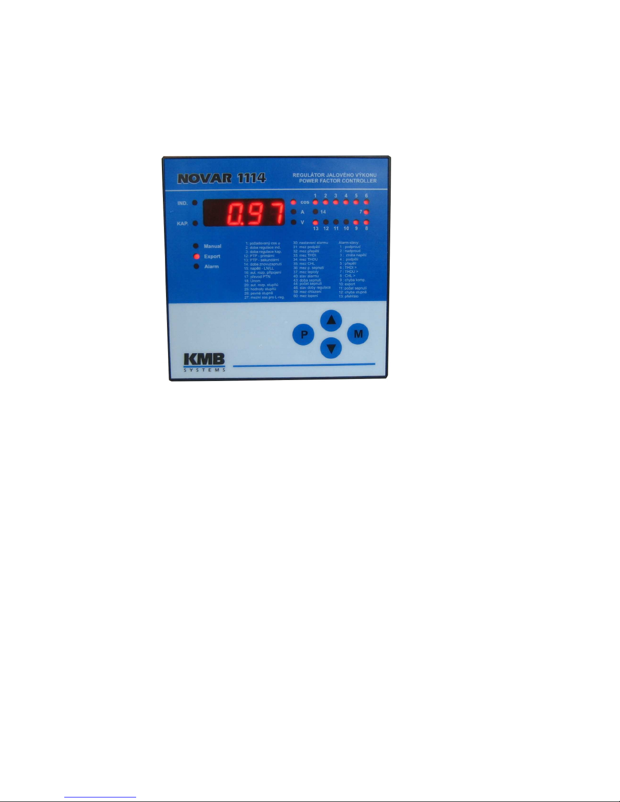
1.8 Front Panel
The front panel consists of a numeric display, indication LEDs and control keys.
Figure 1.1: Front Panel
1.9 Numeric Display
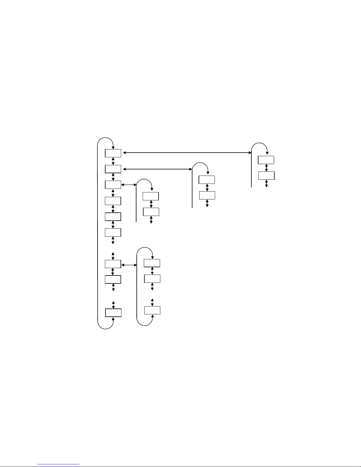
Information shown on the numeric display can be divided into 3 main data groups:
• instantaneous power system values measured, such as power factor, current, voltage,
power, etc.
• controller parameters
• test and error messages
1.9.1 Novar 11xx / 12xx / 13xx Controllers
1.9.1.1 Instantaneous Measurement Values
The mode of displaying instantaneous values is the basic display mode which the controller enters on
power-up. If you switch to parameter display mode, you can get back to instantaneous value display
mode by pressing the M (Measurement) button.
The controller enters the instantaneous display mode automatically in about 30 seconds from the
moment you stop pressing control keys (or in five minutes if control time is displayed – see description
of parameter 46 further below).
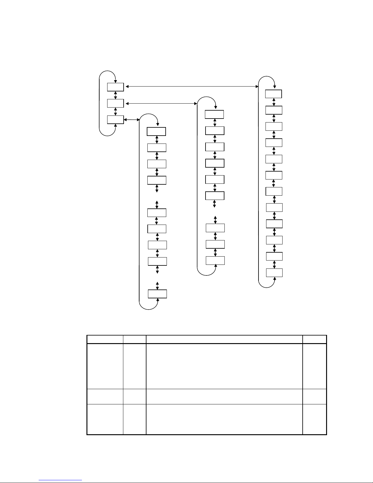
1.9.1.2 Main Branch
One LED, COS or A or V, is always lit in the instantaneous display mode. These LEDs identify the
value group displayed. Instantaneous values displayed are organized in branches – see Figure 1.2.
The main branch contains the following main instantaneous values: cos, Ieff and Ueff. You can
switch between the values displayed using the ▲, ▼ buttons.
Novar 1xxx KMB systems
9
Figure 1.2: Instantaneous value display – structure
Table 1.1: List of Measurement Quantities – Main Branch
abbreviation symbol quantity unit
cos
- Instantaneous power factor. The value corresponds to the ratio of
instantaneous active component to instantaneous total power
fundamental harmonic value in the power system. A positive value
means inductive power factor, negative means capacitive power
factor.
Flashing decimal point indicates offset control activation.
-
Ieff
- Instantaneous current effective value in the power systems
(including higher harmonic components).
A / kA *
Ueff
- Instantaneous voltage effective value in the power system
(including higher harmonic components). By default shown in
volts. If the measurement voltage is connected via a metering
transformer, in kilovolts (see description of parameter 17).
V (kV)
* … in A as default; flashing decimal point indicates value in kA
cos
Ueff
Ieff
cos branch
voltage
branch
main branch
dPre
Pre
Temp
Acos
mincos
Pac
APre
maxPac
maxPre
maxdPre
maxTemp
APac
dIrea
Irea
THDI
3rdharI
5thharI
Iact
19thharI
17thharI
maxTHDI
THDU
CHL
3rdharU
19thharU
F
maxhar3U
maxTHDU
mxhar19U
maxCHL
current
branch

Novar 1xxx KMB systems
10
Pressing the M button switches to the relevant subbranch: to the branch of power factors, power, and
temperature while displaying COS (further as COS Branch), to the current branch while displaying Ieff
(further as A Branch) or to the voltage branch while displaying Ueff (further as V Branch). Again, you
can move up and down the branch using the ▲, ▼ buttons. Displaying values of the subbranches’
quantities is indicated with periodic flashes of the quantity symbol. To get back to the main branch of
instantaneous values press button M.
Tables 1.1 through 1.4 show descriptions of the measurement quantities.
1.9.1.2.1 COS Branch
Instantaneous power values as well as recorded average, maximum and minimum values of selected
quantities are shown in the COS Branch. Power is displayed as three-phase values (single-phase
power values multiplied by three). Reactive power values are prefixed with L for positive values and C
for negative values.
The values recorded can be divided by their nature into three groups:
1. Average values Acos, APac, APre
These are average values of power factor, active and reactive power. The depth of average
can be set in parameter 56 from 1 minute to 7 days.
Note: The average values of active and reactive power are rendered with the sign. If then, for
example, the reactive power value is changing its polarity (it has alternately inductive and
capacitive character), its average value, APre, may become zero even though the
instantaneous reactive power value was not zero at any point in time under evaluation. Also
the power factor average value, which is evaluated from the average active and reactive
power using the formula
Acos =
eAAPac
Pr
APac
22
+
may, in such an event, become 1 even though the instantaneous power factor was never 1
within the time evaluated.
2. Maximum and minimum values mincos, maxPac, maxPre, maxdPre
• mincos – evaluated as a ratio of fundamental harmonic active and reactive power
moving averages. The moving average window size can be specified in parameter
57 from 1 minute to 7 days. The minimum value is recorded and displayed.
Evaluation is conditioned by the corresponding average current being at least 5% of
the nominal load as determined from the metering current transformer turns ratio
primary value (parameter12) else the value is ignored (the value is not recorder for
minimum loads).
• maxPac, maxPre – the maximum values of fundamental harmonic active and
reactive power moving averages. The moving average window size can be specified
in parameter 57 from 1 minute to 7 days.
• maxdPre – the maximum value of fundamental harmonic absent reactive power
moving average. As opposed to the absent reactive power instantaneous value,
dPre, which is the difference between the actual and required reactive power,
irrespective of the instantaneous condition of the controller’s closed outputs,
maxdPre is only evaluated if the required reactive power exceeds the system’s
control capacity (that is the total power of all compensation banks, or sections), and
its value is determined as a difference between this control capacity and required
power (if the control capacity is sufficient, the maxdPre value is zero). The moving
average window size can be specified in parameter 57 from 1 minute to 7 days.

Novar 1xxx KMB systems
11
3. Maximum temperature maxTemp
The temperature moving average maximum value. The moving window depth is fixed at
1 minute.
The above described recorded values can be cleared, each group separately – when clearing a value,
all other values in the same groups are cleared too. Clearing values is explained in the Editing chapter
further down the manual.
Table 1.2: List of Measurement Quantities – COS Branch
abbreviation
symbol quantity unit
Pac
PAC
PACPAC
PAC
Instantaneous fundamental harmonic active power (Power
active).
kW / MW *
Pre
Pre
PrePre
Pre
Instantaneous fundamental harmonic reactive power (Power
reactive).
kvar / Mvar *
dPre
dPre
dPredPre
dPre
Instantaneous fundamental harmonic reactive power difference
to achieve target power factor (Delta Power reactive).
kvar / Mvar *
Temp
OOOO
CCCCor
OOOO
FFFF
Instantaneous temperature (in the distribution board cabinet, at
the controller). Displayed in degrees Celsius or Fahrenheit, as
specified in parameter 58.
°C or °F
Acos
ACOS
ACOSACOS
ACOS
Average power factor in the power system over the time
specified in parameter 56 (Average cos).
—
mincos
nCOS
nCOSnCOS
nCOS
Minimum power factor in the power system achieved since last
clear. The evaluation window is specified in parameter 57.
—
APac
APAC
APACAPAC
APAC
Average fundamental harmonic active power in the power
system over the time specified in parameter 56 (Average
Power active).
kW / MW *
maxPac
mmmmPAC
PACPAC
PAC
Maximum fundamental harmonic active power in the power
system achieved since last clear. The evaluation window is
specified in parameter 57 (Maximum Power active).
kW / MW *
APre
APre
APreAPre
APre
Average fundamental harmonic reactive power in the power
system over the time specified in parameter 56 (Average
Power active).
kvar / Mvar *
maxPre
mPre
mPremPre
mPre
Maximum fundamental harmonic reactive power in the power
system achieved since last clear. The evaluation window is
specified in parameter 57 (Maximum Power reactive).
kvar / Mvar *
maxdPre
mdPr
mdPrmdPr
mdPr
Maximum fundamental harmonic reactive power difference to
achieve target power factor in the power system achieved
since last clear. The evaluation window is specified in
parameter 57 (Maximum Delta Power reactive).
kvar / Mvar *
maxTemp
mmmm
OOOO
CCCC or
MMMM
OOOO
FFFF
Maximum temperature recorded since last clear. The
evaluation is based on temperature one-minute moving
averages (Maximum Temperature).
°C or °F
* … in kW-, kvar- units as default; flashing decimal point indicates value in MW, Mvar
1.9.1.2.2 A Branch
All quantities related to current are shown in this branch. The maxTHDI value can be cleared
manually.
Novar 1xxx KMB systems
12
Table 1.3: List of Measurement Quantities – A Branch
abbreviation
symbol quantity unit
Iact
ACt
ACtACt
ACt
Instantaneous active current fundamental harmonic component
(active).
A / kA *
Irea
reA
reAreA
reA
Instantaneous reactive current fundamental harmonic component
(reactive); L indicates inductive, C indicates capacitive polarity.
A / kA *
dIrea
dreA
dreAdreA
dreA
Instantaneous reactive current fundamental harmonic component
difference to achieve the target power factor in the power system
(Delta reactive).
A / kA *
THDI
tHd
tHdtHd
tHd
Instantaneous level of power system current’s total harmonic
distortion (Total Harmonic Distortion) – shows the ratio of current
higher harmonic components content, up to the 19th harmonic, to the
level of fundamental harmonic. It is only evaluated if the total power
system load is at least 5% of the nominal load in terms of current
determined by the metering current transformer conversion primary
side value (parameter 12).
%
3. ÷ 19.har
H-3
H-3H-3
H-3
÷19
1919
19
Instantaneous current harmonic component level in the power
system.
%
maxTHDI
MtHd
MtHdMtHd
MtHd
Maximum THDI value achieved since last clear. The evaluation is
based on THDI one-minute moving averages.
%
* … in A as default; flashing decimal point indicates value in kA
1.9.1.2.3 V Branch
This branch shows all the quantities related to voltage. They are commonly used quantities. Only the
Capacitor Harmonic Load, CHL, factor needs further explanation – details to be found in chapter 4.9
further below.
The maximum values can be cleared manually. Clearing any of these values clears all the other
maximum values within this branch.
Table 1.4: List of Measurement Quantities – V Branch
abbreviation
symbol quantity unit
F
FFFF
Instantaneous voltage fundamental harmonic component
frequency.
Hz
CHL
CHL
CHLCHL
CHL
Instantaneous value of Capacitor Harmonic Load factor (Capacitor
Harmonic Load).
%
THDU
tHd
tHdtHd
tHd
Instantaneous level of power system voltage’s total harmonic
distortion (Total Harmonic Distortion) – shows the ratio of current
higher harmonic components content, up to the 19th harmonic, to
the level of fundamental harmonic.
%
3. ÷
19.har
H-3
H-3H-3
H-3
÷19
1919
19
Instantaneous level of harmonic component voltage in the power
system.
%
maxCHL
MCHL
MCHLMCHL
MCHL
Maximum CHL value achieved since last clear. The evaluation is
based on CHL one-minute moving averages.
%
maxTHDU
MtHd
MtHdMtHd
MtHd
Maximum THDU value achieved since last clear. The evaluation is
based on THDU one-minute moving averages.
%
3. ÷ 19.
maxharI
MH-3
MH-3MH-3
MH-3
÷19
1919
19
Maximum value of voltage harmonic component achieved since
last clear. The evaluation is based on harmonic component oneminute moving averages.
%
Novar 1xxx KMB systems
13
1.9.1.3 Controller Parameters
You can view controller parameters by pressing the P button (parameters). First the parameter
number shows momentarily and then its value does. The parameter number flashes momentarily
every five seconds for better orientation.
The parameters can be divided into three main groups:
• Parameters determining controller functions. These parameters can be set to direct the
control process. There are target power factor, control period, reconnection delay time,
etc.
• Parameters indicating controller’s current condition. This is the alarm (parameter 40),
error condition (parameter 45), and control time (parameter 46). These parameters’
values are set by the controller and they identify nonstandard or error conditions and
monitor progress of the control process in detail.
• Total connected times recorded and numbers of connections of each compensation
banks, or sections (parameters 43 and 44, respectively). These values are set by the
controller and the operator can only clear them.
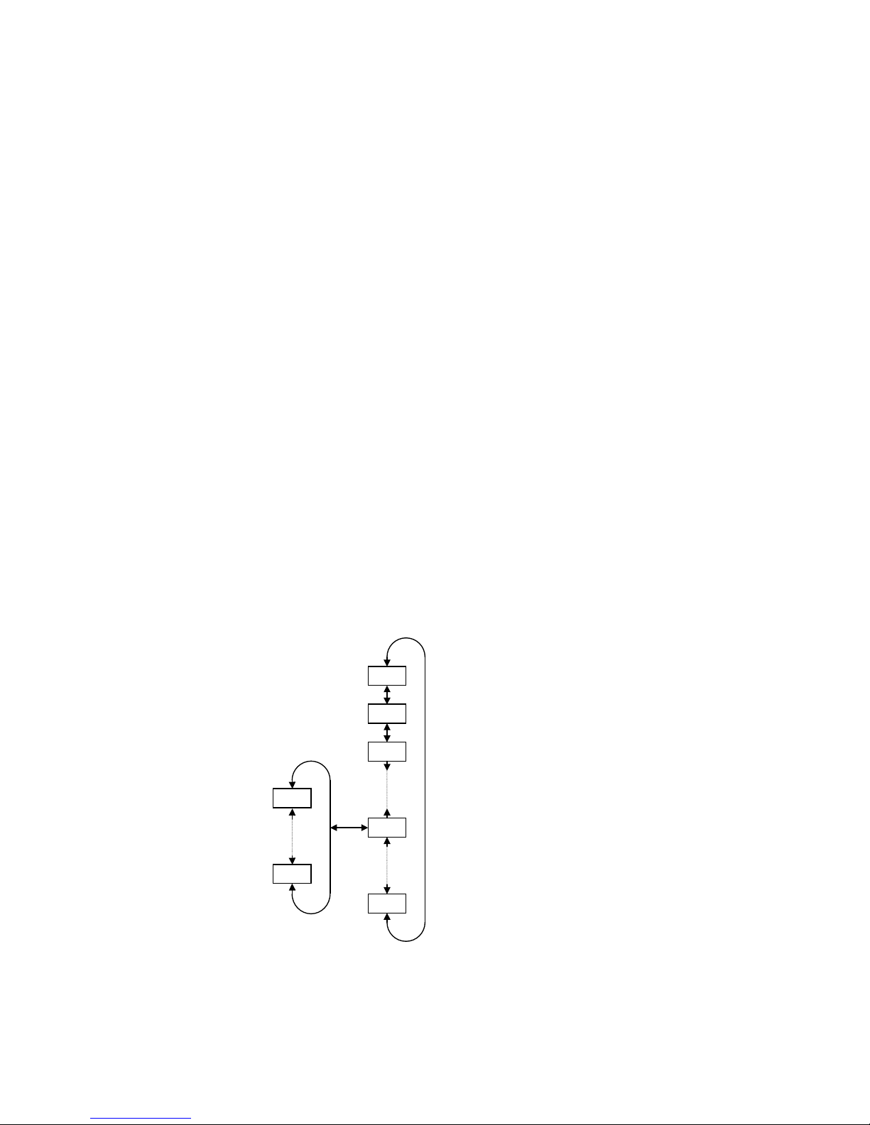
The parameters are organized by ordinal number in the main branch – see Figure 1.3. Some of the
parameters (parameter 25 – sectional power, 26 – fixed sections, 30 – alarm setting, 40 – state of
alarm, 43 – total connected times, 44 – number of sections connected) are located on side branches
for easier navigation. You can switch to a side branch with selected parameters by pressing button P
(parameters) and switch back to the main branch in the same way. Side branch parameter displayed
are identified by a dash between the parameter number and value. For example: in the main branch,
while showing parameter 26 (fixed sections), you will see 01 C
01 C01 C
01 C (section 1 is a capacitive
compensation one); if you want to display conditions of the other sections, you need to switch display
to the side branch by pressing button P; the display will change to 01
0101
01––––CCCC and now you can move up
and down the branch, through all sections’ values. Pressing button P again returns display to the main
branch (the dash disappears).
Figure 1.3: Parameter Display – Structure
Pressing button M (measurement) returns to the instantaneous value display mode. The controller
gets back to this mode automatically in about 30 seconds from the last press of button.
main branch
side branch
P-01
P-03
P-02
P-25
P-xx
01-C
14-C
Novar 1xxx KMB systems
14
Exception: In the Manual mode the parameter values cannot be viewed. Instantaneous output values
are displayed on pressing button P (parameters) — see description further below.
1.9.2 Novar 10xx Controllers
Novar1005, 1007, 1005D and 1007D controllers are equipped with 3 buttons only – instead M- and Pbuttons, they features one ►- button.
Listing through windows is analogic; the only difference is that both instantaneous measured values
and controller parameters are situated in one common main branch, one below another ( see Fig.1.4 ).
Fig. 1.4 : Instantaneous values and parameters (Novar 1005 / 1007)
1.9.3 Test and Error Messages
In the instantaneous value display mode a test or error message pops up in place of an instantaneous
power factor value in some situations. Each message is described further below in more detail. In
these situations, if the value shown does not represent instantaneous power factor, the COS LED
flashes.
1.10 Indication LEDs
Besides the numeric display and adjacent LEDs, COS , A , V, the front panel has some more
indication LEDs.
cos
Ueff
Ieff
cos branch
voltage
branch
main branch
►
Pre
Pac
Irea
Iact
CHL
F
current
branch
P-02
P-01
P-03
P-25
P-xx
P-26 02-C
01-C
08-C
…
side branch

Novar 1xxx KMB systems
15
1.10.1 Output State Indications
The array of LEDs at the top right of the front panel show the current state of output relays. Each LED
is assigned a number from 1 to 14, and if lit, they indicate closed contacts of the corresponding output
relay.
If a LED is flashing, it means the controller wants to connect the output, but it has to wait for the delay
time to elapse. The corresponding output relay contacts are open and they will be closed as soon as
the reconnection delay time has elapsed.
An exception is the power-up display test to check correct operation of all display elements. In this test
the display shows TEST and all indication LEDs come on and go out one by one. All output relays stay
open while the test is running.
1.10.2 Trend Indication
These LEDs show the magnitude of deviation of the true instantaneous reactive power in the power
system from optimum reactive power value which would correspond to the specified value of required
power factor.
If the deviation is smaller than a half of the reactive power value of the smallest capacitor, both LEDs
are dark. If the deviation is greater than a half of, but smaller than, the reactive power value of the
smallest capacitor, the corresponding LED flashes — if lagging (undercompensation), the IND LED
flashes; if leading (overcompensation), the CAP LED flashes. If the deviation exceeds the value of the
smallest capacitor, the corresponding LED is permanently lit.
Exceptions to these LEDs’ meanings are the following situations:
• measurement U and I method of connection is not defined (parameter 16)
• automatic connection configuration detection process is in progress
• automatic section power recognition process is in progress
If the method of connection is not defined, both LEDs flash; they are dark in the other two situations.
1.10.3 Indication of Manual Mode
Flashing Manual LED indicates that the controller is in the manual mode. The controller’s automatic
control function is disabled.
If this LED is dark and display is in the Measurement mode, the controller is in its standard control
mode or it is carrying out automatic connection configuration detection process or automatic section
power recognition process.
1.10.4 Indication of Backfeed (Power Export)
If the controller knows of the method of connection (measurement voltage and current), that is if the
automatic connection configuration detection process has been completed successfully or the method
of connection has been entered manually, the Export LED indicates the power transmission direction.
If it is dark, the power is flowing from the assumed power supply to the appliance. If the LED is lit, the
power is flowing in the opposite direction.
1.10.5 Alarm Indication
An Alarm relay can be used for non-standard events signalling. This relay’s operation can be set up
as described further below ( parameter 30 ). At Novar 10xx controllers that haven’t dedicated alarm
relay it is necessary to select and set alarm relay function first ( parameter 26 ).
The Alarm LED indicates this relay’s condition, that is if the Alarm relay’s output contact is closed, the
LED flashes.
Novar 1xxx KMB systems
16
2. Installation
2.1 Physical
Instruments designed for a distribution board panel are mounted into a cutout of required size. The
instrument’s position must be fixed with locks.
The Novar1005D and theNovar1007D are designed for mounting on a DIN-35 bar.
Natural air circulation should be provided inside the distribution board cabinet, and in the instrument’s
neighbourhood, especially underneath the instrument, no other instrumentation that is source of heat
should be installed or the temperature value measured may be false.
2.2 Connection
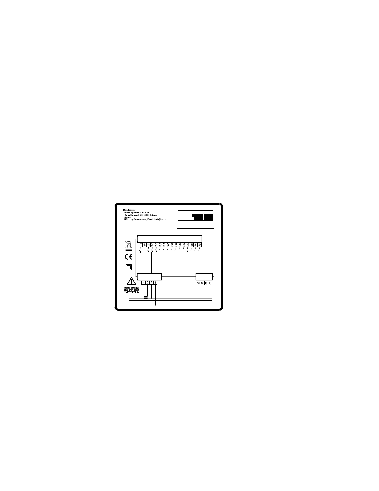
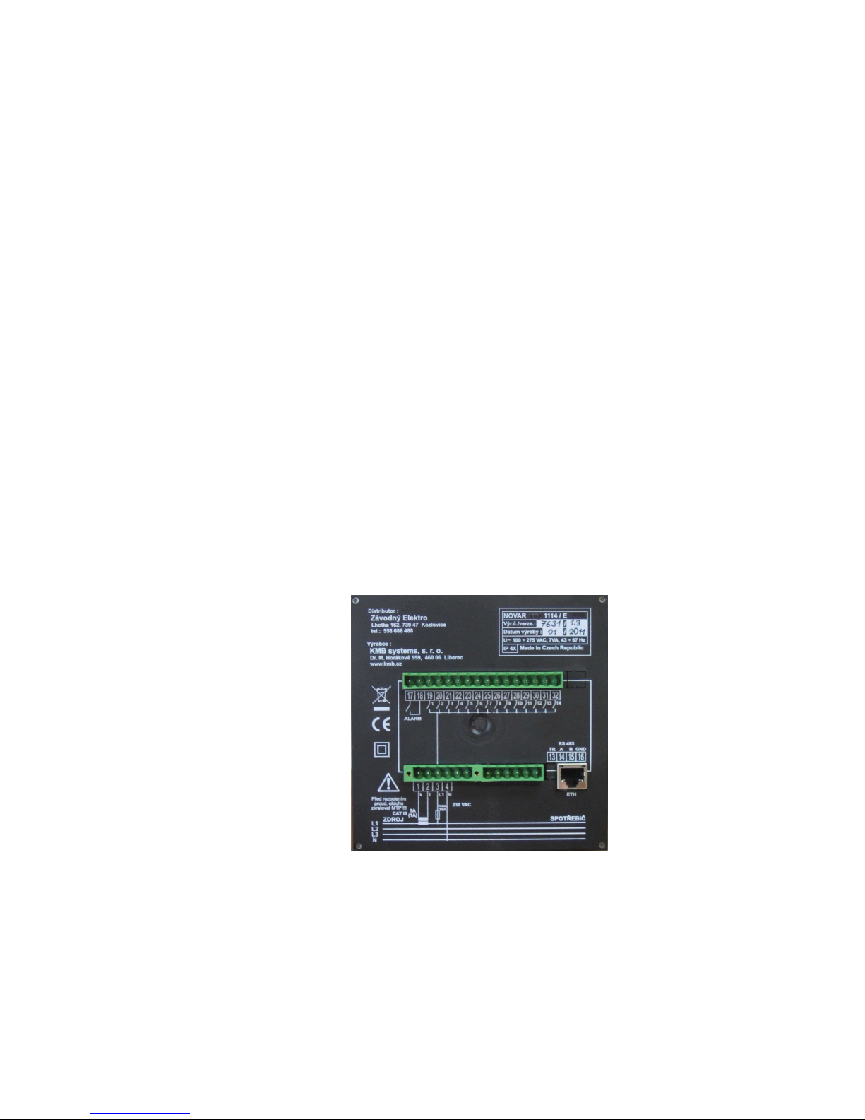
To connect the controller there are connectors with screw-on terminals in the back wall. Signal pinout
on these connectors can be seen from the pictures below.
Examples of controller wiring are shown in a separate chapter.
Fig. 2.1 : Novar1114 controller – connectors
L1
L2
L3
N
1 2 3 4 5 6 7
8 9
1011121314
ALARM
5A
(1A)
max.
10A
100÷275 VAC
k l L N
RS 232/485
Rx
TR A B GND
Tx G ND
Made in Czech Republic
/
/
NOVAR 1106 1114 / 232 485
Serial / vers.:
Product. date :
IP 4X
U 100 275 VAC, 7VA,
÷ ÷
43 67 Hz
SUPPLY
LOAD
Maximum cross section area of connection wires is 2.5 square millimetres.
2.2.1 Power Supply
2.2.1.1 Standard Version Controllers
The controller requires supply voltage in the range as declared in technical specifications table for its
operation.
The supply voltage connects to terminals 3 (L) and 4 (N). In case of DC supply voltage the polarity of
connection is free. Power supply voltage needs to be externally protected ( see chapter Protection
below ).
The 12xx line controllers have power supply terminals 3 (L) and 4 (N) internally connected to terminals
5 (L) and 6 (N) which can be used to connect the power supply voltage to measurement voltage input
(terminals 7 – L and 9 – N/L).
Power supply terminal 3 (L) is internally connected to the common pole of output relays. It is
necessary to dimension the power supply protection in consideration of output contactors’ power as
well.
Novar 1xxx KMB systems
17
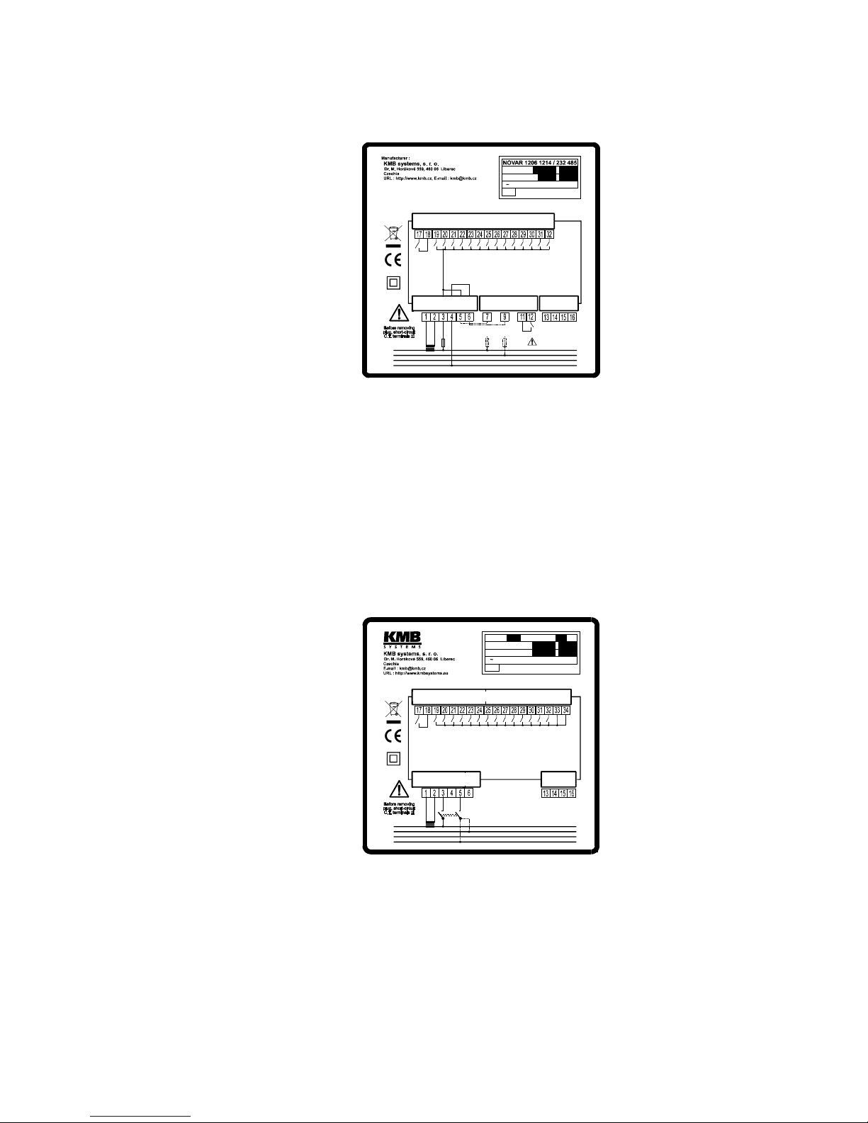
Fig. 2.2 : Novar1214 Controller – Connectors
L1
L2
L3
N
1 2 3 4 5 6 7 8 9
1011121314
ALARM
5A
(1A)
max.
10A
100÷275 VAC
k l L N
RS 232/485
Rx
TR A B GND
Tx GND
Made in Czech Republic
/
/
Serial / vers.:
Product. date :
IP 4X
U 100 275 VAC, 7VA,
÷ ÷
43 67 Hz
SUPPLY
LOAD
58÷690 VAC
N L L/NL
max. 6A
max. 6A
2. TARIF
2.2.1.2 “/S400” Version Controllers
Controllers of the “/S400” version can be supplied with higher voltage – up to 500 V, either AC or DC.
The power demand is the same as those of standard version.
The supply voltage connects to terminals 3 (L1) and 5 (L2/N). In case of DC supply voltage the
polarity of connection is generally free, but for maximum electromagnetic compatibility grounded pole
should be connected to the terminal 5 (L2/N); see connection examples below.
Power supply voltage needs to be externally protected ( see following chapter).
Despite of standard version, power supply terminal 3 (L) is not internally connected to the common
pole of output relays. Terminals 4 and 6 are not used.
Fig. 2.3 : Novar1114/S400 Controller – Connectors
L1
L2
L3
N
1 2 3 4 5 6 7 8 9
1011121314
ALARM
5A
(1A)
max.
500
VAC
L2/N
RS 232/485
Rx
TR A B GND
Tx GND
Made in Czech Republic
/
/
NOVAR 1106 1114 / S400 / 232 485
Serial No / Fw. vers.:
Production date :
IP 4X
U 75 500 V AC, 7 VA,
÷ ÷
43 67 Hz
SUPPLY
LOAD
k
l1AL1
2.2.1.3 Novar 1005 / 1007 Controllers
The supply voltage connects to terminals 4 (L1) and 3 (N). Power supply voltage needs to be
externally protected ( see chapter Protection below ).
Power supply terminal 4 ( L1 ) is internally connected to the common pole of output relays. It is
necessary to dimension the power supply protection in consideration of output contactors’ power as
well.
Novar 1xxx KMB systems
18
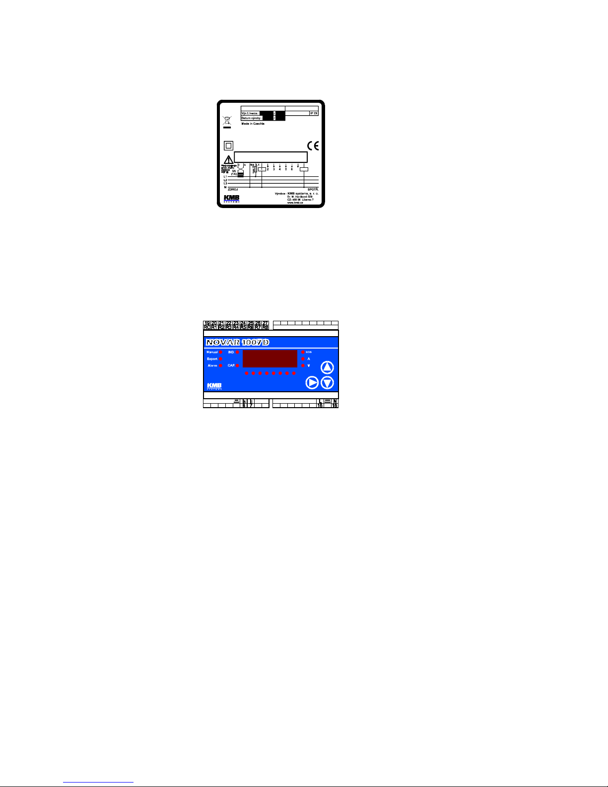
Fig. 2.4 : Novar 1007 Controller – Connector
U~ 80÷275VAC,43÷67Hz
(1007)
(7)
(8)
NOVAR 1005 1007
Příkon 5 VA
2.2.1.4 Novar 1005D / 1007D Controllers
The power supply is connected to terminals 16 (L1) and 18 (N). Power supply voltage needs to be
externally protected ( see chapter Protection below ).
Despite of 1005 / 1007 models, power supply terminal is not internally connected to the common pole
of output relays.
Fig. 2.5 : Novar 1007D Controller
Power Factor Controller
71 2 3 4 5 6 8
9: Comp. error
10: Export
11: Switch No.
12: Step error
13: Temp. >
Alarm States:
1: I <
2: I >
3: U <<
8: CHL >
16: Aut.conn.detect.
20: Aut.step recogn.
25: Steps values
30: Alarm setting
40: Alarm state
1: Target cos
2: Contr. time ind.
3: Contr. time cap.
12,13: CT-ratio
14: Reconn. time
ϕ
0 98
.
2.2.1.5 Protection
Article 6.12.2.1 in the EN 61010-1 standard requires that instrument must have a disconnecting device
in the power supply circuit (a switch — see installation diagram). It must be located at the instrument’s
immediate proximity and easily accessible by the operator. The disconnecting device must be marked
as such. A circuit breaker for nominal current of 10 amp makes a suitable disconnecting device, its
function and working positions, however, must be clearly marked (symbols “0” for power off and “I” for
power on in accordance with EN 61010–1).
Since the controller’s inbuilt power supply is of pulse design, it draws momentary peak current on
powerup which is in order of magnitude of amperes. This fact needs to be kept in mind when selecting
the primary protection devices.
2.2.2 Measurement Voltage
2.2.2.1 11xx and 10xx Line Controllers
The power supply voltage is used as measurement voltage in 11xx line controllers and it is not thus
necessary (or possible) to connect measurement voltage independently.
2.2.2.2 12xx Line Controllers
The 12xx Line Controllers feature a general-purpose, galvanic-isolated voltage measurement input. It
allows to connect measurement voltage in the range from 45 to 760 V AC at the frequency range 43
to 67 Hz of either phase or line voltage. In basic connection phase L1 goes to terminal L (7) and
neutral wire to terminal N/L (9).

Novar 1xxx KMB systems
19
The measurement voltage must be protected externally. If the measurement voltage is identical with
power supply voltage, they can share a circuit breaker. Otherwise each voltage branch must be
protected with fuses or circuit breakers of nominal value 1 to 6 A.
If the measurement voltage is connected via a metering voltage transformer, you have to enter the
transformer turns ratio in instrument setup (parameter 17 – see further below) for correct expression of
measurement values displayed.
2.2.3 Measurement Current
A metering current transformer of nominal output current 5 or 1 A can be used – the metering current
transformer’s ratio must be entered when setting up the instrument for proper measured values
display (parameters 12, 13 – see further below).
2.2.3.1 Novar 11xx / 12xx / 13xx Controllers
Metering current transformer (CT) outputs connect to terminals 1 (k) and 2 (l). At 10xx line controllers,
connection polarity is opposite : terminal 1 is l and terminal 2 is k.
The connector features a screw lock to prevent accidental pull-out.
2.2.3.2 Novar 10xx Controllers
At 1005/1007 controllers, connect a metering current transformer (CT) outputs to terminals 1 (k) and 2
(l).
At 1005D/1007D controllers, terminal numbers are 6 (k) and 7 (l).
2.2.4 Error Indication
2.2.4.1 Novar 11xx / 12xx / 13xx Controllers
The instrument has an auxiliary Alarm relay to indicate nonstandard conditions. This relay’s contact
goes to terminals 17 and 18.
2.2.4.2 Novar 10xx Controllers
Non-standard events can be signalled by one of last two output relays (if they are not used for control).
It is necessary to set such relay function properly, see parameter 26.
2.2.5 Output Relays
The instrument has 6, 8 or 14 output relays (depending on controller model). The relays’ output
contacts are internally wired with varistors.
2.2.5.1 Standard Version Controllers
The relays’ contacts go to terminals 19 through 32.
The relays’ common contacts are internally connected to power supply terminal L ( No. 3 ). When an
output relay contact closes, power supply voltage appears at the corresponding output terminal.
2.2.5.2 “/S400” Version Controllers
The relays’ contacts go to terminals 19 through 32.
Despite of standard version, the relays’ common contacts are connected to additional terminals 33,
34.

Novar 1xxx KMB systems
20
In case of DC voltage for supplying of contactors, installation of suppression 2A/600V diodes directly
at contactors´s coils is strongly recommended. Furthermore, note lower maximum current load of the
controller outputs at such case ( see technical parameters table).
2.2.5.3 Novar 10xx Controllers
The Novar1005 and Novar1007 relays’ contacts go to terminals 5 through 12. The relays’ common
contacts are internally connected to power supply terminal L ( No. 4 )
At the Novar1005D and Novar1007D models, the relays’ contacts go to terminals 20 through 27. The
relays’ common contacts are connected to additional terminal RC ( No. 19 ), that is isolated from
power supply terminals.
In installation there may be a need to test function of each compensation section by manual
connection and disconnection — this can be done in the Manual mode or using manual intervention in
control process (see further below).
2.2.6 Second Metering Rate, External Alarm
In some situations it may be suitable to operate the controller with two different settings, for example
depending on load characteristics in different daily or weekly zones. To select the setting desired,
there is the second metering rate input.
WARNING !!! This input is not galvanically isolated from the controller’s internal circuitry and
its terminals constitute exposure to hazardous voltage against the ground potential! It is
therefore necessary for the relay, switch or optocoupler, driving the input, to be isolated (no external
voltage) and to be located as close to the controller as possible (optimally in the same cabinet) to
minimize the lead length (maximum about 2 to 3 metres). The input is connected to terminals 11 and
12. The input’s internal power supply voltage is about 30 V DC, switching current about 5 mA.
If the second metering rate active device is a transistor (NPN) or optocoupler, it is necessary to
observe the connection polarity – transistor or optocoupler collector to go to terminal + (11) and
emitter to terminal – (12).
When the input is open, the controller operates with the basic metering rate setting, when it is closed
(if the second metering rate function is enabled – see further below), it operates with the second
metering rate setting.
If second metering rate function is switched off, the second metering rate input can be used for
external alarm signal – see description of parameters 30, 40.
Only 12xx and 13xx line controllers feature the second metering rate selection input.
2.2.7 Communication Interface
The controllers can be equipped with galvanically isolated communication interface in compliance with
RS-485 or Ethernet specification for remote setup and control process monitoring.
2.2.7.1 RS-485 Communication Interface
Signal-to-pin configuration for RS-485 type line is shown in Tab. 2.2.
Table 2.2: communication line signal configuration
signal
terminal
TR 13
DATA A 14
DATA B 15
GND/C 16
Novar 1xxx KMB systems
21
The interface allows connecting up to 32 instruments at a distance up to about 1 kilometre.
Recommended cable is shielded twisted metallic double pair. Use one pair for DATA A and DATA B
signals and the second pair for GND/C signal interconnection.
RS-485 line requires impedance termination of the final nodes by installing terminating resistors for
communication distances of a few tens of metres and longer. Terminating resistors matching the
cable’s wave impedance are connected between terminals 14 and 15 (DATA A and DATA B). The
instrument has a built-in terminating resistor of 330 ohms. It is connected between DATA B-signal
(terminal 15) and TR-terminal (13) inside the instrument. To install the resistor, simply interconnect
terminals DATA A (14) and TR (13).
If the communication cable is hundreds of meters long and in environments with electromagnetic
noise it is suitable to use shielded cable. The shielding connects to the PE (protection earth) wire at
one end of the cable.
2.2.7.2 Ethernet (IEEE802.3) Interface
Using this interface the instruments can be connected directly to the local computer network (LAN).
Instruments with this interface are equipped with a corresponding connector RJ- 45 with eight signals
(in accordance with ISO 8877), a physical layer corresponds to 10/100 BASE- T.
Type and maximum length of the required cable must respond to IEEE 802.3. Each instrument must
have a different IP- address, preset during the installation.
Physically, the interface is created with embedded Ethernet-to-serial converter ES01. Setup of the
module can be found in application handbook ES01 Embedded Ethernet to Serial Link Converter that
is available on www.kmbsystems.eu .
Fig. 2.6 : Controller with Ethernet Interface Rear Panel

Novar 1xxx KMB systems
22
3. Putting in Operation
3.1 First Use
The controller comes preset to default values as shown in Table 4.1.
On powerup, display test runs first. The display momentarily shows
• type of controller (e.g. N214
N214N214
N214)
• firmware version (e.g. 1
11
1.2222)
• type of measurement voltage set (U=LN
U=LNU=LN
U=LN or U=LL
U=LLU=LL
U=LL)
• metering current transformer secondary side nominal value set (I=5A
I=5AI=5A
I=5A or I=1A
I=1AI=1A
I=1A)
If the measurement voltage connection is correct, the automatic connection configuration detection
process starts.
If no measurement voltage is detected, U=0
U=0 U=0
U=0 will flash on the display.
3.2 Automatic Connection Configuration Detection Process
The controller’s default measurement voltage and current connection parameters are set as follows:
• type of measurement voltage set to phase voltage (“LN”, parameter 15)
• method of connection of U and I not defined (parameter 16)
• compensation system nominal voltage U
NOM
set to 230 V (parameter 18)
If the method of connection is not defined, the controller cannot evaluate instantaneous power factor
and this condition is indicated by both trend LEDs flashing simultaneously. In such an event, the
controller carries out automatic connection configuration detection process.
For the controller to be able to carry out this automatic connection configuration detection process, the
following conditions must be met:
• controller operation is not disabled (i.e. the Manual LED is dark)
• controller is in the control mode, i.e. the numeric display mode is Measurement
• measurement voltage of the minimum value required is connected
If meeting the three above conditions, the controller starts the automatic connection configuration
detection process.
The process may have up to seven steps. The controller makes four measuring attempts in each step
in which it consecutively connects and disconnects sections 1 through 4. It, at the same time,
assumes that power factor capacitors are connected to at least two of the sections (if any choke
connected to sections 1 through 4, detection process fails). The two following messages are shown,
one after another, in each measurement attempt on the numerical display:

Novar 1xxx KMB systems
23
1. step number in format APnn
APnn APnn
APnn (Automatic Phase detection, nn... attempt number)
2. attempt result, e.g. L1-0
L1-0L1-0
L1-0 (see Table 4.4 for connection methods)
If the controller measures identical values repeatedly in each attempt, it considers the connection
detected and quits carrying out further steps. If the measurement results are different from each other
in a particular step, the controller carries out another measurement step.
The following conditions must be met for successful automatic connection configuration detection
process:
• type of measurement voltage is set correctly (phase, “LN” or line, “LL” – parameter 15)
• at least two power factor capacitors are connected to sections 1 through 4 and no power
factor choke is connected to these sections
The controller measures the measurement voltage value for the whole of the automatic connection
configuration detection process. It evaluates this voltage’s average value at the end of the process
and selects the compensation system nominal voltage U
NOM
(parameter 18) as the nearest value of
the following choice of nominal voltages.
Table 3.1: choice of nominal voltages
58 V 100 V 230 V 400 V 500 V 690 V
Type of connection detected is shown on the numeric display for a moment after successful
completion of the automatic connection configuration detection process, the selected U
NOM
nominal
voltage, the true power factor value in the power system, and thereafter the instrument starts the
control process or it starts the automatic section power recognition process (see further below).
If the automatic connection configuration detection process is not completed successfully, the numeric
display shows flashing P=0
P=0P=0
P=0. It is, in such a case, necessary to enter the type of connection manually
or to re-enter
----
--------
----
(= not defined) in editing parameter 16 and thus restart the automatic connection
configuration detection process. Otherwise the controller changes over to a waiting mode and it
repeats the automatic connection configuration detection process in 15 minutes automatically.
If the actual nominal voltage in the compensation system differs from the value selected and entered
in parameter 18 in the automatic connection configuration detection process, the parameter can be
corrected to its actual value when the process has finished.
The automatic connection configuration detection process can be interrupted at any time by switching
the numeric display mode to Parameters. The automatic connection configuration detection process
will start again from scratch on return to instantaneous value display mode.
3.3 Automatic Section Power Recognition Process
The controllers come with enabled function of automatic section power recognition process (parameter
20 set to A) as default setting. The controller starts the automatic section recognition power process
on powerup (connection of power supply voltage) with this setting, provided none of the outputs (in
parameter 25) has a valid power value; this happens if a new controller is installed for the first time or
after its initialization). The process can also be started without interrupting the power supply voltage
connection, by editing parameter 20 to value 1 or by controller initialization (see further below).

Novar 1xxx KMB systems
24
For the controller to be able to start the automatic section power recognition process, the following
conditions must be met:
• controller automatic operation is not disabled (i.e. the Manual LED is dark)
• controller is in control mode, i.e. the numeric display mode is Measurement
• measurement voltage, at minimum value required, is connected
• connection mode of measurement U and I is defined (parameter 16)
If these conditions are met, the controller starts the automatic section power recognition process.
The process may have three or six steps. The controller consecutively connects and disconnects each
output in each step. While doing that, it measures the effect of connection and disconnection on total
reactive power in the power system. From the values measured the power of each section is
determined.
The following messages are shown one after another in each measurement attempt on the numeric
display:
1. Step number in format AC-n
AC-nAC-n
AC-n (n... step number).
2. Sectional power measured in kvars; the nominal power value of the section under
measurement is displayed, that is the value that corresponds to nominal voltage U
NOM
of
the compensation system as specified in parameter 18. If the metering current
transformer turns ratio has been entered (parameters 12 and 13), or, if measuring voltage
via a metering voltage transformer, the voltage transformer’s turns ratio as well (in
parameter 17), sectional power in the power system is shown (that is at the metering
current transformer primary side, or metering voltage transformer primary side). If the
metering current transformer primary side (parameter 12), or metering voltage transformer
primary side (parameter 17) is not defined, sectional power in the metering current
transformer’s, or the metering voltage transformer’s, secondary side is shown.
If the controller does not succeed in determining a section’s value, it does not show it. This condition
occurs if reactive power value in the power system fluctuates considerably due to changes in load.
After carrying out three steps, evaluation is carried out. If each measurement in the steps carried out
provides sufficiently stable results, the automatic section power recognition process is completed.
Otherwise the controller carries out three more steps.
A requirement for successful automatic section power recognition process is sufficiently stable
condition of the power system – while connecting or disconnecting a section, the reactive load power
must not change by a value which is comparable with, or even greater than, the reactive power value
of the section under test. Otherwise the measurement result is unsuccessful. As a rule of thumb, the
section values are recognized the more precisely, the lower the load is in the power system.
On successful completion of automatic section power recognition process, the controller checks
whether at least one capacitive section has been detected and, if so, it starts control. Otherwise the
controller goes to the waiting mode and after 15 minutes it starts the automatic section power
recognition process again.
Each section value recognized can be checked in the side branch of parameter 25. A positive power
value means a capacitive section, negative value means inductive section. If the value could not be
recognized, “----
--------
----” is shown. Each value recognized can be edited manually.
 Loading...