

Klutch NT1D Operator's Manual
Model/Modelo:
NT1D
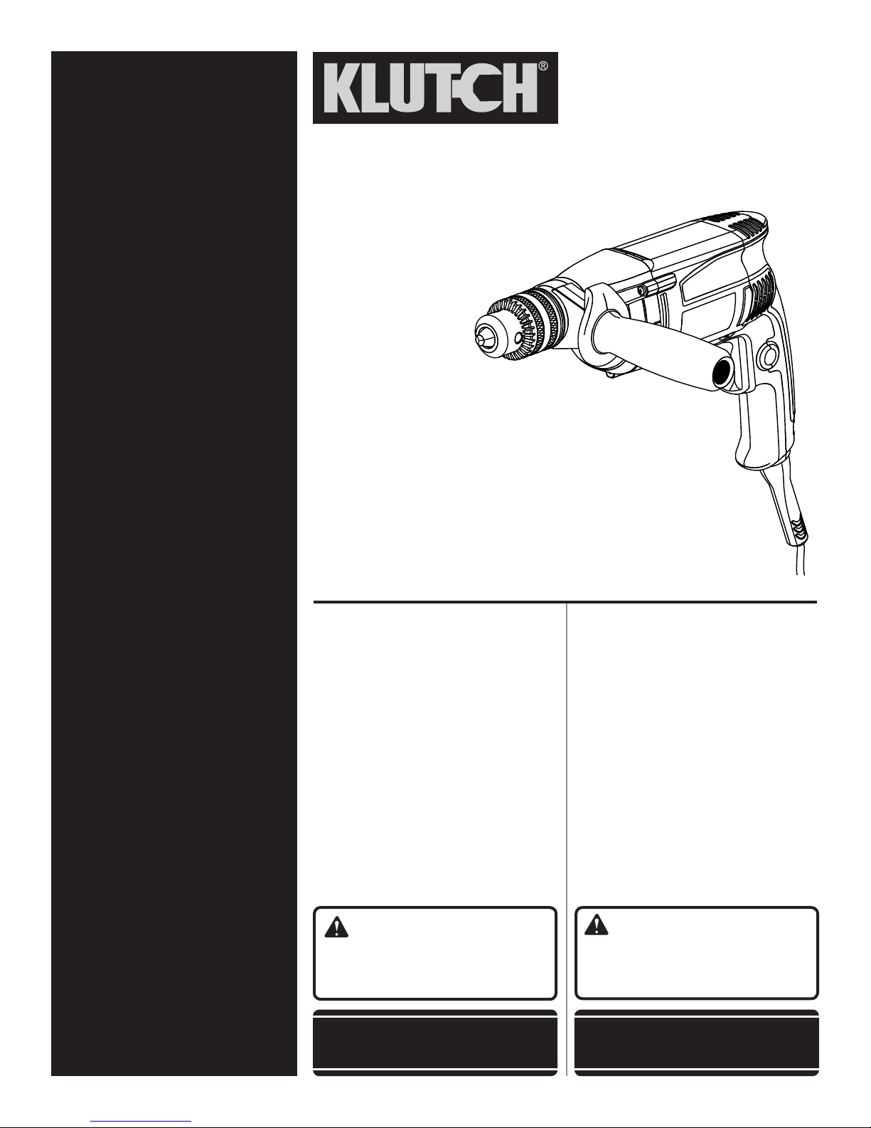
1/2 in. DRILL
TALADRO DE
13 mm (1/2 pulg.)
OPERATOR’S MANUAL
MANUAL DEL OPERADOR
CUSTOMER SERVICE
SERVICIO AL CLIENTE
1-800-556-7885
TABLE OF CONTENTS
Warranty ...............................................2
General Power Tool Safety
Warnings ...........................................3-4
Drill Safety Warnings ............................4
Symbols ................................................5
Electrical ............................................... 6
Features ................................................ 7
Assembly .............................................. 7
Operation ...........................................8-9
Maintenance ....................................... 10
Accessories ........................................ 10
Figures (Illustrations) .....................11-12
Parts Ordering and
Service ..................................Back page
WARNING: To reduce the risk of
injury, the user must read and understand
the operator’s manual before using this
product.
SAVE THIS MANUAL FOR
FUTURE REFERENCE
ÍNDICE DE CONTENIDO
Garantía ................................................ 2
Advertencias de seguridad
para herramientas eléctricas .............3-4
Advertencias de seguridad taladro ......4
Símbolos ..............................................5
Aspectos eléctricos .............................. 6
Características .....................................7
Armado ................................................. 7
Funcionamiento .................................8-9
Mantenimiento ....................................10
Accesorios .......................................... 10
Figuras (illustraciones) ...................11-12
Pedidos de piezas y
servicio ............................ Pág. posterior
ADVERTENCIA: Para reducir el
riesgo de lesiones, el usuario debe leer
y comprender el manual del operador
antes de usar este producto.
GUARDE ESTE MANUAL
PARA FUTURAS CONSULTAS

WARRANTY / GARANTÍA
KLUTCH POWER TOOL – LIMITED THREE YEAR WARRANTY
Northern Tool and Equipment warrants its KLUTCH power tools with the following conditions:
WHAT THIS WARRANTY COVERS: This KLUTCH power tool is warranted to the original purchaser only to be free from defects in
material and workmanship subject to certain exceptions and limitations stated below, for a period of three (3) years after the date
of purchase. Batteries and chargers sold with your KLUTCH power tool are warranted to the original purchaser only to be free from
defects in material and workmanship subject to certain exceptions and limitations stated below, for a period of one (1) year after the
date of purchase.
HOW TO GET SERVICE: Just return the power tool or batteries, properly packaged and postage prepaid to an Authorized KLUTCH
Service Center. You can obtain the location of the Authorized KLUTCH Service Center nearest you by contacting a service representative
at Northern Tool and Equipment, 2800 Southcross Drive West, Burnsville, MN 55306, by calling 1-800-556-7885 or by logging on
to www.northerntool.com. When you request warranty service, you must also present proof of purchase documentation, which
includes the date of purchase (for example, a bill of sale). We will repair any faulty workmanship, and either repair or replace any part
covered under the warranty, at our option. We will do so without any charge to you.
WHAT’S NOT COVERED: This warranty applies only to the original purchaser at retail and may not be transferred. This warranty only
covers manufacturing defects and does not cover part failure or damage due to normal wear or any malfunction, failure, or defect
resulting from misuse, abuse, neglect, alteration, lack of maintenance, accidents, modification or repairs made or attempted by anyone
other than an Authorized KLUTCH Service Center. Northern Tool and Equipment makes no warranties, representations or promises
as to the quality or performance of its power tools other than those specifically stated in this warranty.
ADDITIONAL LIMITATIONS: To the extent permitted by applicable law, any implied warranties granted under state law, including
all warranties of merchantability or fitness for a particular purpose, that cannot be disclaimed under state law are limited to three
(3) years from the date of purchase. Northern Tool and Equipment is not responsible for direct, indirect, incidental or consequential
damages. No retailer or other party has any authority to create any other warranty or add to or vary this limited warranty. Northern Tool
and Equipment’s maximum liability in any event under this warranty will not exceed the purchase price paid by the original purchaser.
Some states do not allow limitations on how long an implied warranty lasts and/or do not allow the exclusion or limitation of incidental
or consequential damages, so the above limitations and exclusions may not apply to you. This warranty gives you specific legal rights,
and you may also have other rights which vary from state to state.
HERRAMIENTA ELÉCTRICA KLUTCH - GARANTÍA LIMITADA DE TRES AÑOS
Northern Tool and Equipment garantiza sus herramientas eléctricas KLUTCH con las siguientes condiciones:
LO QUE CUBRE ESTA GARANTÍA: Esta garantía de la herramienta eléctrica KLUTCH se ofrece exclusivamente al comprador
original y cubre los defectos en los materiales y en la mano de obra sujetos a ciertas excepciones y limitaciones que se indican a
continuación, durante un período de tres (3) años a partir de la fecha de compra. La garantía de las baterías y cargadores vendidos
con la herramienta eléctrica KLUTCH se ofrece exclusivamente al comprador original y cubre los defectos en los materiales y en la
mano de obra sujetos a ciertas excepciones y limitaciones que se indican a continuación, durante un período de un (1) año a partir
de la fecha de compra.
FORMA DE OBTENER SERVICIO TÉCNICO: Simplemente envíe la herramienta eléctrica o las baterías, debidamente empaquetadas
y con franqueo pagado a un Centro de servicio técnico autorizado de KLUTCH. Puede obtener información sobre la ubicación del
Centro de servicio técnico autorizado de KLUTCH más cercano escribiendo a Northern Tool and Equipment, 2800 Southcross Drive
West, Burnsville, MN 55306, llamando al 1-800-556-7885 o ingresando en www.northerntool.com. Cuando solicite el servicio
técnico de garantía, también deberá presentar el comprobante de compra que incluya la fecha de compra (por ejemplo, una factura
de venta). Repararemos toda mano de obra deficiente del producto y repararemos o reemplazaremos cualquier pieza cubierta por
la garantía, a nuestra sola discreción. Lo haremos sin cargarle ningún costo a usted.
LO QUE NO ESTÁ CUBIERTO: Esta garantía se ofrece exclusivamente al comprador original minorista y no puede transferirse.
Esta garantía sólo cubre defectos de fábrica y no cubre fallas de las piezas o daños debidos al desgaste normal o a cualquier
malfuncionamiento, falla o defecto por el uso indebido, maltrato, negligencia, alteración, falta de mantenimiento, accidentes,
modificaciones o reparaciones efectuadas o intentadas por terceros ajenos a los Centros de servicio técnico autorizados de KLUTCH.
Northern Tool and Equipment no ofrece ninguna garantía, declaración o promesa en relación con la calidad o el desempeño de sus
herramientas eléctricas más que las señaladas específicamente en esta garantía.
LIMITACIONES ADICIONALES: En la medida en que lo permitan las leyes aplicables, cualquier garantía implícita otorgada de
conformidad con las leyes estatales, incluidas las garantías de comerciabilidad o idoneidad para un uso particular que no pueden ser
negadas según las leyes estatales, están limitadas a tres (3) años a partir de la fecha de compra. Northern Tool and Equipment no es
responsable de daños directos, indirectos, incidentales o consecuentes. Los vendedores minoristas o terceros no tienen autorización
para crear cualquier otra garantía o realizar adiciones o cambios a esta garantía limitada. La responsabilidad máxima de Northern Tool
and Equipment ante cualquier caso descrito en esta garantía no sobrepasará el precio de compra pagado por el comprador original.
Algunos estados no permiten limitaciones en cuanto al período de vigencia de una garantía implícita y/o no permiten la exclusión o
limitación de los daños incidentales o consecuentes, por lo que es posible que estas limitaciones y exclusiones no se apliquen en
su caso. Esta garantía le confiere derechos legales específicos, y es posible que usted además goce de otros derechos, los cuales
pueden variar de estado a estado.
2

GENERAL POWER TOOL SAFETY WARNINGS
WARNING:
Read all safety warnings and all instructions. Failure to
follow the warnings and instructions may result in electric
shock, fire and/or serious injury.
Save all warnings and instructions for future reference.The
term “power tool” in the warnings refers to your mains-operated
(corded) power tool or battery-operated (cordless) power tool.
WORK AREA SAFETY
Keep work area clean and well lit. Cluttered or dark
areas invite accidents.
Do not operate power tools in explosive atmospheres,
such as in the presence of flammable liquids, gases
or dust. Power tools create sparks which may ignite the
dust or fumes.
Keep children and bystanders away while operating a
power tool. Distractions can cause you to lose control.
ELECTRICAL SAFETY
Power tool plugs must match the outlet. Never modify
the plug in any way. Do not use any adapter plugs with
earthed (grounded) power tools. Unmodified plugs and
matching outlets will reduce risk of electric shock.
Avoid body contact with earthed or grounded surfaces
such as pipes, radiators, ranges and refrigerators.
There is an increased risk of electric shock if your body
is earthed or grounded.
Do not expose power tools to rain or wet conditions.
Water entering a power tool will increase the risk of
electric shock.
Do not abuse the cord. Never use the cord for carrying,
pulling or unplugging the power tool. Keep cord away
from heat, oil, sharp edges or moving parts. Damaged
or entangled cords increase the risk of electric shock.
When operating a power tool outdoors, use an
extension cord suitable for outdoor use. Use of a cord
suitable for outdoor use reduces the risk of electric shock.
If operating a power tool in a damp location is
unavoidable, use a ground fault circuit interrupter
(GFCI) protected supply. Use of a GFCI reduces the risk
of electric shock.
PERSONAL SAFETY
Stay alert, watch what you are doing and use common
sense when operating a power tool. Do not use a
power tool while you are tired or under the influence
of drugs, alcohol or medication. A moment of inattention
while operating power tools may result in serious personal
injury.
Use personal protective equipment. Always wear eye
protection. Protective equipment such as dust mask, non-
skid safety shoes, hard hat, or hearing protection used for
appropriate conditions will reduce personal injuries.
Prevent unintentional starting. Ensure the switch is in
the off-position before connecting to power source
and/or battery pack, picking up or carrying the tool.
Carrying power tools with your finger on the switch or
energising power tools that have the switch on invites
accidents.
Remove any adjusting key or wrench before turning
the power tool on. A wrench or a key left attached to a
rotating part of the power tool may result in personal injury.
Do not overreach. Keep proper footing and balance at
all times. This enables better control of the power tool in
unexpected situations.
Dress properly. Do not wear loose clothing or jewellery.
Keep your hair, clothing and gloves away from moving
parts. Loose clothes, jewellery or long hair can be caught
in moving parts.
If devices are provided for the connection of dust
extraction and collection facilities, ensure these are
connected and properly used. Use of dust collection
can reduce dust-related hazards.
Do not wear loose clothing or jewelry. Contain long
hair. Loose clothes, jewelry, or long hair can be drawn
into air vents.
Do not use on a ladder or unstable support. Stable
footing on a solid surface enables better control of the
power tool in unexpected situations.
POWER TOOL USE AND CARE
Do not force the power tool. Use the correct power
tool for your application. The correct power tool will
do the job better and safer at the rate for which it was
designed.
Do not use the power tool if the switch does not turn
it on and off. Any power tool that cannot be controlled
with the switch is dangerous and must be repaired.
Disconnect the plug from the power source and/or
the battery pack from the power tool before making
any adjustments, changing accessories, or storing
power tools. Such preventive safety measures reduce
the risk of starting the power tool accidentally.
Store idle power tools out of the reach of children and
do not allow persons unfamiliar with the power tool
or these instructions to operate the power tool. Power
tools are dangerous in the hands of untrained users.
Maintain power tools. Check for misalignment or
binding of moving parts, breakage of parts and any other
condition that may affect the power tool’s operation. If
damaged, have the power tool repaired before use. Many
accidents are caused by poorly maintained power tools.
3 - English

GENERAL POWER TOOL SAFETY WARNINGS
Keep cutting tools sharp and clean. Properly maintained
cutting tools with sharp cutting edges are less likely to
bind and are easier to control.
Use the power tool, accessories and tool bits etc.
in accordance with these instructions, taking into
account the working conditions and the work to be
performed. Use of the power tool for operations different
from those intended could result in a hazardous situation.
DRILL SAFETY WARNINGS
Use auxiliary handle(s), if supplied with the tool. Loss
of control can cause personal injury.
Hold power tool by insulated gripping surfaces, when
performing an operation where the cutting accessory
may contact hidden wiring or its own cord. Cutting
accessory contacting a “live” wire may make exposed
metal parts of the power tool “live” and could give the
operator an electric shock.
Know your power tool. Read operator’s manual
carefully. Learn its applications and limitations, as well
as the specific potential hazards related to this tool.
Following this rule will reduce the risk of electric shock,
fire, or serious injury.
Always wear eye protection with side shields marked
to comply with ANSI Z87.1. Following this rule will
reduce the risk of serious personal injury.
Protect your lungs. Wear a face or dust mask if the
operation is dusty. Following this rule will reduce the risk
of serious personal injury.
Protect your hearing. Wear hearing protectors during
extended periods of operation. Following this rule will
reduce the risk of serious personal injury.
Inspect tool cords periodically and, if damaged, have
repaired at your nearest authorized service center.
Constantly stay aware of cord location. Following this
rule will reduce the risk of electric shock or fire.
Check damaged parts. Before further use of the
tool, a guard or other part that is damaged should
SERVICE
Have your power tool serviced by a qualified repair
person using only identical replacement parts. This
will ensure that the safety of the power tool is maintained.
When servicing a power tool, use only identical
replacement parts. Follow instructions in the
Maintenance section of this manual. Use of unauthorized
parts or failure to follow Maintenance instructions may
create a risk of shock or injury.
be carefully checked to determine that it will operate
properly and perform its intended function. Check for
alignment of moving parts, binding of moving parts,
breakage of parts, mounting, and any other conditions
that may affect its operation. A guard or other part that
is damaged should be properly repaired or replaced
by an authorized service center. Following this rule will
reduce the risk of shock, fire, or serious injury.
Make sure your extension cord is in good condition.
When using an extension cord, be sure to use one
heavy enough to carry the current your product will
draw. A wire gauge size (A.W.G.) of at least 14 is
recommended for an extension cord 50 feet or less in
length. A cord exceeding 100 feet is not recommended.
If in doubt, use the next heavier gauge. The smaller
the gauge number, the heavier the cord. An undersized
cord will cause a drop in line voltage resulting in loss of
power and overheating.
Inspect for and remove all nails from lumber before
using this tool. Following this rule will reduce the risk of
serious personal injury.
If the power supply cord is damaged, it must be replaced
only by the manufacturer or by an authorized service
center to avoid risk.
Save these instructions. Refer to them frequently and
use them to instruct others who may use this tool. If you
loan someone this tool, loan them these instructions also.
4 - English
SYMBOLS
The following signal words and meanings are intended to explain the levels of risk associated with this product.
SYMBOL SIGNAL MEANING
DANGER:
WARNING:
CAUTION:
NOTICE:
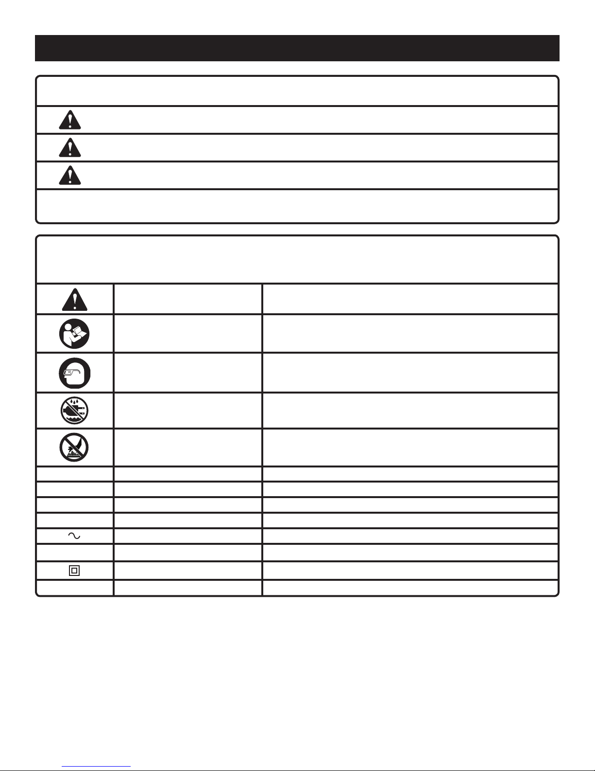
Some of the following symbols may be used on this product. Please study them and learn their meaning. Proper
interpretation of these symbols will allow you to operate the product better and safer.
SYMBOL NAME DESIGNATION/EXPLANATION
Safety Alert Indicates a potential personal injury hazard.
Read Operator’s Manual
Wear Eye Protection
Indicates an imminently hazardous situation, which, if not avoided, will result
in death or serious injury.
Indicates a potentially hazardous situation, which, if not avoided, could result
in death or serious injury.
Indicates a potentially hazardous situation, which, if not avoided, may result in
minor or moderate injury.
(Without Safety Alert Symbol) Indicates important information not related to an
injury hazard, such as a situation that may result in property damage.
To reduce the risk of injury, user must read and understand
operator’s manual before using this product.
Always wear eye protection with side shields marked to comply
with ANSI Z87.1.
Wet Conditions Alert Do not expose to rain or use in damp locations.
Hot Surface
V Volts Voltage
A Amperes Current
Hz Hertz Frequency (cycles per second)
min Minutes Time
Alternating Current Type of current
n
o
.../min Per Minute Revolutions, strokes, surface speed, orbits etc., per minute
No Load Speed Rotational speed, at no load
Class II Construction Double-insulated construction
To reduce the risk of injury or damage, avoid contact with any hot
surface.
5 - English
ELECTRICAL
DOUBLE INSULATION
Double insulation is a concept in safety in electric power tools,
which eliminates the need for the usual three-wire grounded
power cord. All exposed metal parts are isolated from the
internal metal motor components with protecting insulation.
Double insulated tools do not need to be grounded.
WARNING:
The double insulated system is intended to protect
the user from shock resulting from a break in the tool’s
internal wiring. Observe all normal safety precautions to
avoid electrical shock.
NOTE: Servicing of a tool with double insulation requires
extreme care and knowledge of the system and should
be performed only by a qualified service technician. For
service, we suggest you return the tool to your nearest
authorized service center for repair. Always use original
factory replacement parts when servicing.
ELECTRICAL CONNECTION
This tool has a precision-built electric motor. It should be
connected to a power supply that is 120 volts, 60 Hz, AC
only (normal household current). Do not operate this tool
on direct current (DC). A substantial voltage drop will cause
a loss of power and the motor will overheat. If the tool does
not operate when plugged into an outlet, double-check the
power supply.
EXTENSION CORDS
When using a power tool at a considerable distance from
a power source, be sure to use an extension cord that has
the capacity to handle the current the tool will draw. An
undersized cord will cause a drop in line voltage, resulting in
overheating and loss of power. Use the chart to determine
the minimum wire size required in an extension cord. Only
round jacketed cords listed by Underwriter’s Laboratories
(UL) should be used.
When working outdoors with a tool, use an extension cord that
is designed for outside use. This type of cord is designated
with “W-A” or “W” on the cord’s jacket.
Before using any extension cord, inspect it for loose or
exposed wires and cut or worn insulation.
**Ampere rating (on tool data plate)
0-2.0 2.1-3.4 3.5-5.0 5.1-7.0 7.1-12.0 12.1-16.0
Cord Length Wire Size (A.W.G.)
25' 16 16 16 16 14 14
50' 16 16 16 14 14 12
100' 16 16 14 12 10 —
**Used on 12 gauge - 20 amp circuit.
NOTE: AWG = American Wire Gauge
WARNING:
Keep the extension cord clear of the working area.
Position the cord so that it will not get caught on lumber,
tools or other obstructions while you are working with a
power tool. Failure to do so can result in serious personal
injury.
WARNING:
Check extension cords before each use. If damaged
replace immediately. Never use tool with a damaged cord
since touching the damaged area could cause electrical
shock resulting in serious injury.
6 - English
FEATURES
PRODUCT SPECIFICATIONS
Chuck ....................................................................... 1/2 in.
Switch ............................. VSR (Variable Speed Reversible)
No Load Speed ....................................0-850 r/min. (RPM)
Input ............................... 120 V, 60 Hz, AC only, 8.0 Amps
Net Weight ................................................................. 5 lbs.
KNOW YOUR DRILL
See Figure 1, page 11.
The safe use of this product requires an understanding of
the information on the tool and in this operator’s manual as
well as a knowledge of the project you are attempting. Before
use of this product, familiarize yourself with all operating
features and safety rules.
AUXILIARY HANDLE ASSEMBLY
Your drill is equipped with an auxiliary handle assembly. For
ease of operation, you may use the handle with either the
left hand or the right hand.
ASSEMBLY
UNPACKING
This product has been shipped completely assembled.
Carefully remove the tool and any accessories from the
box. Make sure that all items listed in the packing list are
included.
DIRECTION OF ROTATION SELECTOR
(FORWARD/REVERSE)
Your drill has a direction of rotation (forward/reverse) selector
located above the switch trigger for changing the direction
of bit rotation.
LOCK-ON BUTTON
The lock-on button is convenient for continuous drilling for
extended periods of time.
VARIABLE SPEED
The variable speed switch trigger delivers higher speed with
increased trigger pressure and lower speed with decreased
trigger pressure.
WARNING:
If any parts are damaged or missing do not operate this
tool until the parts are replaced. Use of this product
with damaged or missing parts could result in serious
personal injury.
WARNING:
Do not use this product if it is not completely assembled
or if any parts appear to be missing or damaged. Use of
a product that is not properly and completely assembled
could result in serious personal injury.
Inspect the tool carefully to make sure no breakage or
damage occurred during shipping.
Do not discard the packing material until you have
carefully inspected and satisfactorily operated the tool.
If any parts are damaged or missing, please call
1-800-556-7885 for assistance.
WARNING:
Do not attempt to modify this tool or create accessories
not recommended for use with this tool. Any such
alteration or modification is misuse and could result in a
hazardous condition leading to possible serious personal
injury.
WARNING:
Do not connect to power supply until assembly is
complete. Failure to comply could result in accidental
starting and possible serious personal injury.
7 - English
OPERATION
WARNING:
Do not allow familiarity with products to make you
careless. Remember that a careless fraction of a second
is sufficient to inflict severe injury.
WARNING:
INSTALLING/REMOVING BITS
See Figures 4 - 5, page 11.
Unplug the drill.
Insert the chuck key and twist counterclockwise.
Open or close the chuck jaws to a point where the opening
is slightly larger than the bit size you intend to use. Also,
raise the front of the drill slightly to keep the bit from falling
out of the chuck jaws.
Always wear eye protection with side shields marked to
comply with ANSI Z87.1. Failure to do so could result in
objects being thrown into your eyes, resulting in possible
serious injury.
APPLICATIONS
You may use this tool for the purposes listed below:
Drilling in wood
Drilling in ceramics, plastics, fiberglass, and laminates
Drilling in metals
Mixing paint
VARIABLE SPEED SWITCH TRIGGER
See Figure 2, page 11.
The variable speed switch trigger delivers higher speed with
increased trigger pressure and lower speed with decreased
trigger pressure.
To turn the tool ON, depress the switch trigger. To turn it
OFF, release the switch trigger and allow the coupler to
come to a complete stop.
NOTE: A whistling or ringing noise coming from the switch
during use is a normal part of the switch function.
DIRECTION OF ROTATION SELECTOR
(FORWARD/REVERSE)
See Figure 3 page 11.
The direction of bit rotation is reversible and is controlled
by a selector located above the switch trigger. With the tool
held in normal operating position, the direction of rotation
selector should be positioned to the left of the switch trigger
for forward rotation. The direction is reversed when the
selector is to the right of the switch trigger.
NOTE: The tool will not run unless the direction of rotation
selector is pushed fully to the left or right.
NOTICE:
To prevent gear damage, always allow the chuck to
come to a complete stop before changing the direction
of rotation.
Avoid running the drill at low speeds for extended periods
of time. Running at low speeds under constant usage may
cause the drill to become overheated. If this occurs, cool the
drill by running it without a load and at full speed.
WARNING:
Make sure to insert the drill bit straight into the chuck
jaws. Do not insert the drill bit into the chuck jaws at
an angle then tighten, as shown in figure 5. This could
cause the drill bit to be thrown from the drill, resulting in
possible serious personal injury or damage to the chuck.
Insert the drill bit.
Tighten the chuck jaws securely on the drill bit, using the
chuck key provided.
Remove the chuck key and return it to the storage area.
USING THE AUXILIARY HANDLE ASSEMBLY
See Figure 6, page 11.
Your drill is equipped with an auxiliary handle assembly. For
ease of operation, use the handle with either the left or right
hand. The handle can be rotated 360°.
To adjust the auxiliary handle assembly:
Loosen the handle assembly by turning the handle
counterclockwise.
Rotate the handle assembly to the desired operating
position.
Securely tighten by turning the handle assembly
clockwise.
NOTE: For convenience and ease of starting threads, the
hex nut has been trapped inside the molded slot in the
handle assembly.
LOCK-ON BUTTON
See Figure 7, page 12.
This drill is equipped with a lock-on feature, which is
convenient for continuous drilling for extended periods of time.
To lock-on:
Depress the switch trigger.
Push in and hold the lock-on button, located on the side
of the handle.
Release the switch trigger.
Release the lock-on button and the drill will continue
running.
To release the lock, depress and release the switch trigger.
If the lock-on feature is engaged during use and the drill
becomes disconnected from the power supply, disengage
the lock-on feature immediately.
8 - English
 Loading...