

Klutch 49564 Owner's Manual

Thank you very much for choosing a Klutch product. For future reference, please complete the
owner’s record below:
Serial Number/Lot Date Code: _______________ Purchase Date: _______________
Save the receipt, warranty and these instructions. It is important that you read the entire manual
to become familiar with this product before you begin using it.
This Milling and Drilling Machine is designed for certain applications only. Northern Tool and
Equipment cannot be responsible for issues arising from modification or use of this product in
an application for which it was not designed. We strongly recommend that this product not be
modified and/or used for any application other than that for which it was designed.
For technical questions please call 1-800-222-5381.
Table of Contents
Table of Contents................................................................................................................................1
Intended Use.......................................................................................................................................1
Technical Specifications....................................................................................................................2
Important Safety Information.............................................................................................................2
Specific Operation Warnings..............................................................................................................5
Grounding...........................................................................................................................................5
Extension Cords..................................................................................................................................6
Unpacking Instructions.......................................................................................................................6
The Machine Assembly.......................................................................................................................8
The Transmission System...............................................................................................................8
The Electrical System......................................................................................................................8
Controls............................................................................................................................................9
Before Each Use...............................................................................................................................10
Operating Instructions......................................................................................................................10
Lubricating the Machine................................................................................................................11
The Drilling and Milling Feed..........................................................................................................12
Longitudinal and Transverse Feeds...............................................................................................12
The Tailstock..................................................................................................................................12
The Tool Post..................................................................................................................................13
Changing the Speed of the Drilling/Milling Spindle.......................................................................13
Changing the Speed of the Turning Spindle..................................................................................14
Installing/Removing a Drilling/Milling Tool....................................................................................14
Installing/Removing the Spindle Chuck........................................................................................16
Machine Adjustments....................................................................................................................18
After Each Use..................................................................................................................................20
Maintenance.....................................................................................................................................20
Parts Diagram...................................................................................................................................21
Parts List ..........................................................................................................................................28
Replacement Parts...........................................................................................................................33
Limited Warranty...............................................................................................................................33
Intended Use
This milling and drilling machine is a light-duty multipurpose machine designed for turning, drilling,
and milling metal and other materials. It can be widely applied for single part and mass production
in all kinds of small-sized enterprises and repair industries.
Milling and Drilling Machine
OWNER’S MANUAL
Milling and Drilling Machine
OWNER’S MANUAL
Item# 49564
1 of 34
WARNING:
Read carefully and understand all ASSEMBLY AND OPERATION
INSTRUCTIONS before operating. Failure to follow the safety rules and
other basic safety precautions may result in serious personal injury.

Milling and Drilling Machine
OWNER’S MANUAL
Milling and Drilling Machine
OWNER’S MANUAL
Technical Specifications
Turning
Drilling and Milling
Other
Important Safety Information
WARNING:
• Read and understand all instructions. Failure to follow all instructions may result in serious
injury or property damage.
• The warnings, cautions, and instructions in this manual cannot cover all possible conditions
or situations that could occur. Exercise common sense and caution when using this tool.
Always be aware of the environment and ensure that the tool is used in a safe and
responsible manner.
• Do not allow persons to operate or assemble the product until they have read this manual
and have developed a thorough understanding of how it works.
• Do not modify this product in any way. Unauthorized modification may impair the function
and/or safety and could affect the life of the product. There are specific applications for
which the product was designed.
• Use the right tool for the job. DO NOT attempt to force small equipment to do the work of
larger industrial equipment. There are certain applications for which this equipment was
designed. It will do the job better and more safely at the capacity for which it was intended.
DO NOT use this equipment for a purpose for which it was not intended.
• Industrial or commercial applications must follow OSHA requirements.
WARNING:
• This product may contain chemicals known to the State of California to cause cancer, birth
defects or other reproductive harm.
• Some dust created by power sanding, sawing, grinding, drilling, and other construction
activities contains chemicals known to the State of California to cause cancer, birth defects,
or other reproductive harm. Some examples of these chemicals are:
- lead from lead-based paints,
- crystalline silica from bricks and cement and other masonry products, and
- arsenic and chromium from chemically-treated lumber.
Your risk from these exposures varies, depending on how often you do this type of work. To
reduce your exposure to these chemicals: work in a well-ventilated area, and work with
approved safety equipment, such as dust masks that are specially designed to filter out
microscopic particles.
• Handling power cords on corded products may expose you to lead, a chemical known to the
State of California to cause cancer and birth defects or other reproductive harm. Wash your
hands after handling.
WARNING:
WORK AREA SAFETY
• Inspect the work area before each use. Keep work area clean, dry, free of clutter, and well lit.
Cluttered, wet, or dark work areas can result in injury. Using the milling and drilling machine
in confined work areas may put you dangerously close to other cutting tools and rotating
parts.
• Do not use the milling and drilling machine where there is a risk of causing a fire or an
explosion; e.g., in the presence of flammable liquids, gases, or dust. The product can create
sparks, which may ignite the flammable liquids, gases, or dust.
• Do not allow the milling and drilling machine to come into contact with an electrical source.
The tool is not insulated and contact will cause electrical shock.
• Keep children and bystanders away from the work area while operating the tool. Do not allow
children to handle the milling and drilling machine.
• Be aware of all power lines, electrical circuits, water pipes, and other mechanical hazards in
your work area. Some of these hazards may be hidden from your view and may cause
personal injury and/or property damage if contacted.
WARNING:
PERSONAL SAFETY
• Stay alert, watch what you are doing, and use common sense when operating the tool. Do
not use the tool while you are tired or under the influence of drugs, alcohol, or medication. A
moment of inattention while operating the tool may result in serious personal injury.
• Dress properly. Do not wear loose clothing, dangling objects, or jewelry. Keep your hair,
clothing and gloves away from moving parts. Loose clothes, jewelry, or long hair can be
caught in moving parts. Air vents on the tool often cover moving parts and should be
avoided.
• Wear the proper personal protective equipment when necessary. Use ANSI Z87.1 compliant
safety goggles (not safety glasses) with side shields, or when needed, a face shield. Use a
dust mask in dusty work conditions. Also use non-skid safety shoes, hardhat, gloves, dust
collection systems, and hearing protection when appropriate. This applies to all persons in
the work area.
• Do not overreach. Keep proper footing and balance at all times.
2 of 34 3 of 34
Property
Max. Swing over Bed:
Max. Turning Diameter (for medium carbon steel):
Max. Distance between Centers:
Max. longitudinal Stroke:
Max. Transverse Stroke:
Morse Taper of Spindle Hole:
Bore Diameter of Spindle:
Morse Taper of Tailstock Hole:
Spindle Speed:
Turning Motor:
Specification
14"
1-1/2"
11-13/16"
8-1/4"
5-3/4"
No. 3
3/4"
No. 2
500, 900, 1600 RPM
370W
Property
Max. Drilling Diameter:
Morse Taper of Drilling and Milling Spindle Hole:
Max. Diameter of End Mill:
Max. Diameter of Facer:
Max. Stroke of Milling Quill:
Spindle Speeds:
Drilling and Milling Motor:
Specification
5/8"
No. 2
1/2"
2-1/2"
3"
5 steps 430 – 2000RPM (220V)
4 steps 430 – 1500RPM (110V)
370W
Property
Area of Bench (L x W):
Turn-Round of Drilling – Milling Box:
Overall Dimensions (L x W x H):
Net Weight:
Shipping Weight:
Specification
6"×8"
±90°
35” × 22-3/4” × 31-3/4”
326 lbs.
387 lbs.

Milling and Drilling Machine
OWNER’S MANUAL
Milling and Drilling Machine
OWNER’S MANUAL
• Do not use the tool when tired or under the influence of drugs, alcohol or medication.
• Ensure the power switch is off prior to plugging in the tool.
• Remove keys or wrenches before connecting the tool to an air supply, power supply, or
turning on the tool. A wrench or key that is left attached to a rotating part of the tool may
cause personal injury.
• Secure the work with clamps or a vise instead of your hand when practical. This safety
precaution allows for proper tool operation using both hands.
WARNING:
ELECTRICAL SAFETY
• Grounded tools must be plugged into an outlet properly installed and grounded in accordance
with all codes and ordinances. Never remove the grounding prong or modify the plug in any
way. Do not use any adapter plugs. Check with a qualified electrician if you are in doubt as to
whether the outlet is properly grounded. If the tools should electrically malfunction or break
down, grounding provides a low resistance path to carry electricity away from the user.
• Double insulated tools are equipped with a polarized plug (one blade is wider than the other).
This plug will fit in a polarized outlet only one way. If the plug does not fit fully in the outlet,
reverse the plug. If it still does not fit, contact a qualified electrician to install a polarized
outlet. Do not change the plug in any way. Double insulation eliminates the need for the three
wire grounded power cord and grounded power supply system.
• Do not allow the product to come into contact with an electrical source. The tool is not
insulated and contact will cause electrical shock.
• Avoid body contact with grounded surfaces such as pipes, radiators, ranges, and
refrigerators. There is an increased risk of electric shock if your body is grounded.
• Do not expose power tools to rain or wet conditions. Water entering a power tool will
increase the risk of electric shock.
• Do not abuse the power cord. Never use the power cord to carry the tools or pull the plug
from an outlet. Keep the power cord away from heat, oil, sharp edges, or moving parts.
Replace damaged power cords immediately. Damaged power cords increase the risk of
electric shock.
• When operating a power tool outside, use an outdoor extension cords marked “W-A” or “W”.
These extension cords are rated for outdoor use, and reduce the risk of electric shock.
CAUTION:
MILLING AND DRILLING MACHINE USE AND CARE
• Do not force the product. Products do a better and safer job when used in the manner for
which they are designed. Plan your work, and use the correct product for the job.
• Check for damaged parts before each use. Carefully check that the product will operate
properly and perform its intended function. Replace damaged or worn parts immediately.
Never operate the product with a damaged part.
• Do not use a product with a malfunctioning switch. Any power tool that cannot be controlled
with the power switch is dangerous and must be repaired by an authorized service
representative before using.
• Disconnect the power/air supply from the product and place the switch in the locked or off
position before making any adjustments, changing accessories, or storing the tool. Such
preventive safety measures reduce the risk of starting the tool accidentally.
• Store the product when it is not in use. Store it in a dry, secure place out of the reach of
children. Inspect the tool for good working condition prior to storage and before re-use.
• Use only accessories that are recommended by the manufacturer for use with your product.
Accessories that may be suitable for one product may create a risk of injury when used with
another tool. Never use an accessory that has a lower operating speed or operating pressure
than the tool itself.
• Keep guards in place and in working order. Never operate the product without the guards in
place.
• Do not leave the tool running unattended.
Specific Operation Warnings
WARNING:
• To prevent serious injury or property damage read owner’s manual before operating.
• DO NOT wear loose clothing, jewelry, gloves, or unrestrained hair that may get caught in
moving parts of the machine.
• Wear the proper safety gear including ANSI Z87.1 compliant eye protection.
• Moving Parts Hazard. Keep hands clear of spindle chuck and rotating bit or work piece.
• Remove keys and adjusting wrenches before starting the machine.
• Feed cutter into work piece against direction of rotation.
• Always secure work piece before machining operation.
• DO NOT operate without guards in place.
• Electric shock hazard. Be sure equipment is properly grounded.
• Turn power OFF before servicing.
• Not for use by or around children.
Grounding
WARNING:
• This machine must be grounded while in use to protect the operator from electrical shock.
This drill press is equipped with an electric cord that has an equipment-grounding conductor
and a grounding plug. The plug MUST be plugged into a matching receptacle that is properly
installed and grounded in accordance with ALL local codes and ordinances.
• DO NOT MODIFY THE PLUG PROVIDED. If it will not fit the receptacle, have the proper
receptacle installed by a qualified electrician.
• CHECK with a qualified electrician or service person if you do not completely understand the
grounding instructions, or if you are not sure the tool is properly grounded.
Grounded Tools: Tools with 3-Prong Plugs
Tools marked with Grounding Required have a 3-wire cord and 3-prong grounding plug. The
plug must be connected to a properly grounded outlet. If the tool should electrically malfunction
or break down, grounding provides a low resistance path to carry electricity away from the
user, reducing the risk of electric shock. (See Figure A.)
The grounding prong in the plug is connected through the green wire inside the cord to the
grounding system in the tool. The green wire in the cord must be the only wire connected to the
tool’s grounding system and must never be attached to an electrically live terminal.
Your tool must be plugged into an appropriate outlet, properly installed and grounded in
accordance with all codes and ordinances. The plug and outlet should look like those in the
following illustration.
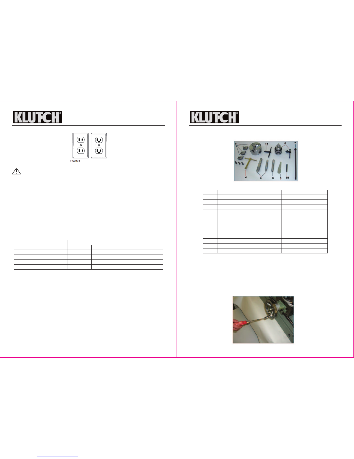
Double Insulated Tools: Tools with Two-Prong Plugs
Tools marked Double Insulated do not require grounding. They have a special double insulation
system which satisfies OSHA requirements and complies with the applicable standards of
Underwriters Laboratories, Inc., the Canadian Standard Association, and the National Electrical
Code. (See Figure B.)
Double insulated tools may be used in either of the 120 volt outlets shown in the following
illustration.
4 of 34 5 of 34
150'
14 AWG
12 AWG
12 AWG
Nameplate AMPS
25'
18 AWG
18 AWG
16 AWG
14 AWG
50'
16 AWG
16 AWG
16 AWG
12 AWG
100'
16 AWG
14 AWG
14 AWG
Minimum Wire Size Of Extension Cords
0-6
6-10
10-12
12-16
Cord Length
NOT RECOMMENDED
6 of 34 7 of 34
Milling and Drilling Machine
OWNER’S MANUAL
Extension Cords
WARNING:
• USE A PROPER EXTENSION CORD. Make sure your extension cord is in good condition.
When using an extension cord, be sure to use one heavy enough to carry the current your
product will draw. An undersized cord will cause a drop in line voltage, resulting in loss of
power and cause overheating.
• Be sure your extension cord is properly wired and in good condition. Always replace a
damaged extension cord or have it repaired by a qualified person before using it. Protect
your extension cords from sharp objects, excessive heat and damp or wet areas.
• Grounded tools require a 3-wire extension cord. Double Insulated tools can use either a 2- or
3-wire extension cord.
• As the distance from the supply outlet increases, you must use a heavier gauge extension
cord. Using extension cords with inadequately sized wire causes a serious drop in voltage,
resulting in loss of power and possible tool damage.
• The smaller the gauge number of the wire, the greater the capacity of the cord. For example,
a 14-gauge cord can carry a higher current than a 16-gauge cord. Minimum extension cord
wire size is shown in the following table:
• When using more than one extension cord to make up the total length, make sure each cord
contains at least the minimum wire size required.
• If you are using one extension cord for more than one tool, add the nameplate amperes and
use the sum to determine the required minimum cord size.
• If you are using an extension cord outdoors, make sure it is marked with the suffix W-A (W in
Canada) to indicate it is acceptable for outdoor use.
• Make sure your extension cord is properly wired and in good electrical condition. Always
replace a damaged extension cord or have it repaired by a qualified electrician before using
it.
• Protect your extension cords from sharp objects, excessive heat, and damp or wet areas.
Unpacking Instructions
This machine has been inspected and tested before delivery. Once it is properly installed it can
be operated immediately. The machine is covered with water-proof and oil-resisting cloth, fixed
tightly on a pallet and packed in wooden crate. In the crate, there is also a box of accessories.
The steel fastening straps around the crate are under tension. Cut off the straps with shears.
When removing the straps, the workers should wear eye-protecting glasses and gloves. Please
take care since the sheared edges are very sharp. After taking off the straps, remove the nails
and unpack the wooden crate.
Milling and Drilling Machine
OWNER’S MANUAL
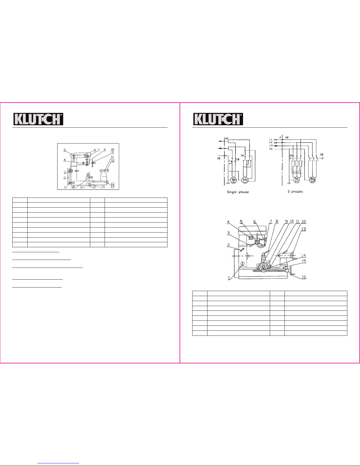
Open the box of accessories and check the accessories according to the photo shown below
(Fig.1). Check them with the Packing List.
When installing the machine, the user should provide a solid pedestal to support the machine.
The pedestal should be level and well adjusted. The installation location should allow enough
area for operating. On the left of the machine, there should be enough area for turning rod
material.
On the surface of the machine, there is a protective layer of oil which can be cleaned with
noncorrosive kerosene or petroleum solvent. After installation and cleaning, the machine should
be lubricated (see Operating Instruction/Lubrication).
For shipping reasons, the feeding handle of the Transverse Wheel (9) was installed inwards.
Before operation, it should be reinstalled outwards as shown in Fig. 2.
No.
1
2
3
4
5
6
7
8
9
10
11
12
Description
Milling/Drilling Machine
Spindle chuck, jaws (3), set screws (3)
Dead Centers
Pressing Cutter Wrench
Wedge
Drilling Chuck & Key
Draw Bar
Drill Taper Shank
Flange (on machine)
Locking Lever
Owner’s Manual (this manual)
Chuck Key
Specification
L-H007
Ø100
Morse No. 2 & 3
JS16
MT #2
Qty.
1
1
1 each
1
1
1
1
1
1
1
1
1
Fig. 1: Accessories
Fig. 2
8 of 34 9 of 34
Milling and Drilling Machine
OWNER’S MANUAL
The Machine Assembly
The Transmission System
Transmission of the Spindle: The spindle motor drives the belt pulley (1), and through the Belt
(2), drives the belt pulley (3) to realize the spindle transmission.
Transmission of Drilling and Milling: The drilling and milling motor drives the motor pulley (5),
and through the belt (6), drives the belt pulley (7) to realize the spindle transmission.
Longitudinal and Transverse Transmission: The longitudinal feed transmission is carried out by
longitudinal thread (13) and nut (14); the transverse feed transmission is carried out by
transverse thread (15) and nut (16).
Transmission of the Tool Post: The tool post feed transmission is performed by tool post thread
(17) and nut (18).
Transmission of the Tailstock: The tailstock feed transmission is achieved by tailstock thread
(12) and nut (11).
The Electrical System
This machine is powered by two separate AC motors. The motion of turning motor is controlled
by a combination switch SA, and the motion of drilling and milling motor by a button switch SB
(Fig. 4).
For safety purposes, the machine should be grounded.
A 10A fuse should be fixed in front of the supply socket to maintain short circuit protection.
Milling and Drilling Machine
OWNER’S MANUAL
Controls
Note: The controls shown below in Fig. 5 and listed in the table are referred to by these
numbers in the Before Each Use and Operating Instructions sections.
REF
1
2
3
4
5
6
7
8
9
Description
Motor Pulley
V-Belt A—1000
Pulley
Coiled Spring
Motor Pulley
V-Belt A-710
Big Pulley
Gear
Worm Gear
Part No.
10
11
12
13
14
15
16
17
18
Description
Worm
Nut
Tailstock Thread
Longitudinal Thread
Longitudinal Nut
Transverse Thread
Transverse Nut
Toolpost Thread
Nut
REF
1
2
3
4
5
6
7
8
Description
Combination Switch
Handle for Locking Box
Drilling/Milling Feed Handle
Button Switch
Clutch Handle
Fine-Feed Handle
Handle for Locking Quill
Handle for Locking Tool Post
Part No.
9
10
11
12
13
14
15
16
Description
Transverse Wheel
Tool Post Handle Wheel
Transverse Lock Handle
Tailstock Quill Lock Handle
Tailstock Hand Wheel
Longitudinal Lock Handle
Handle for Locking Tailstock
Longitudinal Handle Wheel
Fig. 3: Diagram of Transmission System
Fig. 4: Diagram of the Electrical System
Fig. 5: Machine Controls

10 of 34 11 of 34
Milling and Drilling Machine
OWNER’S MANUAL
Controls Operation
The combination switch (1) controls the spindle for forward rotation, reverse rotation and stop.
Turn the handle in the right direction for forward rotation of the spindle; keep it in middle
position for stop; turn it in the left direction for reverse rotation. WARNING: Only when the
spindle stops completely can the rotational direction be reversed.
The button switch (4) is to control the motion of the drilling/milling motor. The green button
(right side) is for starting and the red button (left side) for stopping.
The operation of the mechanical controls (feed handles etc.) is described in the Operating
Instructions section.
Before Each Use
WARNING:
• Check for damaged parts before each use. Carefully check that all the controls operate
properly and the machine will perform its intended function. Replace damaged or worn parts
immediately. Never operate the machine with any damaged part.
• Do not use the machine with a malfunctioning switch. Any power tool that cannot be
controlled with the power switch is dangerous and must be repaired by an authorized service
technician before use.
Note: The control numbers given below in parentheses refer to Fig. 5 in the Controls section
above.
Before each use, loosen all the locking handles:
• Turn the Handle for Locking Box (2) counter-clockwise to turn the drilling/milling head
• Loosen the Handle for Locking Quill (7) to lift or lower the quill
• Loosen the Longitudinal Lock Handle (14) to perform the longitudinal motion of the lower
slide
• Loosen the Transverse Lock Handle (11) to adjust the transverse motion of the bench
• Loosen the Handle for Locking Tailstock (15) to move the tailstock
• Loosen the Tailstock Quill Lock Handle (12) and turn the Tailstock Hand Wheel (13) to
adjust the quill forward and backward
While operating, be sure the relevant locking handles are locked.
While moving the lower slide, bench and tailstock, adjust relevant fix screws and locking
handles to their proper positions so that the sliding parts can be moved steadily and reliably,
and the hand wheels turn easily.
Operating Instructions
WARNING:
Principles
• Before operating the machine, make sure you are familiar with the transmission system (see
page 10) and all the functions of the controls of the machine (see page 12).
• Do not force the machine. Tools do a better and safer job when used in the manner for which
they are designed. Plan your work, and use the correct tool for the job.
• Keep children and bystanders away from the work area while operating the machine. Do not
allow children to operate the machine.
• Never move or damage the warning plates on the machine.
• Use only recommended accessories with this machine. Accessories that may be suitable for
one machine may create a risk of injury when used with a different machine. Never use an
accessory that has a lower maximum operating speed than this machine.
Operational
• Remove adjusting keys or wrenches before turning on the machine. A wrench or key that is
left attached to a rotating part of the machine may cause personal injury.
• Never put wrenches, cutters, files or other tools on the guide rails, where notches or burrs
can affect its accuracy.
• Put the power switches in the off positions before making any adjustments or changing
accessories. Such preventive safety measures reduce the risk of starting the machine
accidentally.
• Changing speed, direction, or any parts should be performed only after the machine is
completely stopped. Never touch the running spindle, workpiece, or other moving parts with
your hands or other methods. Be extremely careful when removing or reinstalling any pivotal
parts.
• Do not leave the machine running unattended.
• The workpiece must be tightly clamped to prevent personal injury or damage to the machine.
Periodic
• To ensure the service life of the guiding rails, pay attention to the cleanliness and lubrication
of the rail surface. Especially when processing cast workpieces, it is necessary to regularly
clean the scrapers on the rails.
• Periodically check the tension of belt, making proper adjustment to reduce any vibration.
Lubricating the Machine
As shown in an example in Fig. 6, all oil points should be oiled manually with #30 engine oil
according to the requirements in Fig. 7. Lubricate the machine once at the beginning of each
shift and again half-way through the shift according to the Diagram of Lubrication.
• The surfaces of rails and quill, and leading thread, tool post, and tailstock should be oiled
according to their operation conditions.
• All bearings should be cleaned and greased once per year.
Note: The control numbers given below in parentheses refer to Fig. 5 in the Controls section
above.
Milling and Drilling Machine
OWNER’S MANUAL
Fig. 7: Lubrication Diagram
Fig. 6
 Loading...