

Klutch 426246 Owner's Manual

4IN. x 36IN. BELT/6IN. DISC SANDER
OWNER’S MANUAL
WARNING:
Read carefully and understand RULES FOR SAFE OPERATION and instructions
before operating. Failure to follow the safety rules and other basic safety
precautions may result in serious personal injury.
Item# 426246

4IN. x 36IN. BELT/6IN. DISC SANDER
OWNER’S MANUAL
1 of 7
Thank you very much for choosing a Klutch Product! For future
reference, please complete the owner’s record below:
Model: _______________ Purchase Date: _______________
Save the receipt, warranty and these instructions. It is important that you read the entire manual to become familiar with
this product before you begin using it.
This machine is designed for certain applications only. The
distributor strongly recommends this machine is not modified
and/or used for any application other than that for which it was
designed. If you have any questions relative to a particular
application, DO NOT use the machine until you have first
contacted the distributor to determine if it can or should be
performed on the product.
For technical questions and replacement parts, please call
1-800-222-5381.
TECHNICAL SPECIFICATIONS
Applications:
Edge sanding, Surface sanding, Chamfer and bevel sanding,
Contour sanding, Finish sanding.
Included Accessories:
Abrasive Belt: 4 x36in., 120 Grit, 80 Grit, 50 Grit
Abrasive Discs6in. in assorted grits
GENERAL SAFETY RULES
WARNING: Read and understand all instructions.
Failure to follow all instructions listed below may result
in serious injury.
WARNING:The warnings, cautions, and instructions
discussed in this owner's manual cannot cover all
possible conditions or situations that could occur. It must be
understood by the operator that common sense and caution
are factors, which cannot be built into this product, but must
be supplied by the operator.
SAVE THESE INSTRUCTIONS
WORK AREA SAFETY
• Keep your work area clean and well lighted.Cluttered and
dark work areas invite accidents.
• Do not operate power tools in explosive atmospheres, such
as in the presence of flammable liquids, gases, dust or rain.
Power tools create sparks which may ignite the dust or
fumes.
• Proper electrical receptacle should be available for tool.
Three-prong plug should be plugged directly into properly
grounded, three-prong receptacle.
• Extension cords should have a grounding prong and the
three wires of the extension cord should be of the correct
gauge.
• Keep bystanders at a safe distance while operating a
power tool. Distractions can cause you to lose control.
Protect others in the work area from debris such as chips
and sparks. Provide barriers or shields as needed.
• Keep children out of workplace. Make workshop childproof.
Use padlocks, master switches or remove switch keys to
prevent any unintentional use of power tools.
PERSONAL SAFETY
• Stay alert. Watch what you are doing, and use common
sense when operating a power tool. Never use power tools
when tired or under the influence of drugs, alcohol or
medication. A moment of inattentiveness while operating
power tools may result in serious personal injury.
• Dress properly. Do not wear loose clothing or jewelry. Keep
your hair, clothing and gloves away from moving parts.
• Use safety equipment. Always wear eye protection. A dust
mask, non-skid safety shoes, a hard hat and hearing protection must be used when the conditions demand them.
• Remove adjusting keys and wrenches before turning the
power tool on. A wrench or a key that is left attached to a
rotating part of the power tool may result in personal injury.
• Do not overreach. Keep proper footing and balance at all
times. Proper footing and balance enables better control of
the power tool in unexpected situations.
• Wear safety glasses complying with United States ANSI
Z87.1. Everyday glasses have only impact resistant lenses.
They are NOT safety glasses.
ELECTRICAL SAFETY
• Do not expose power tools to rain or wet conditions. Water
entering a power tool will increase the risk of electric shock.
• Grounded tools must be plugged into an outlet properly
installed and grounded in accordance with all codes and
ordinances. Never remove the grounding prong or modify
the plug in any way. Do not use any adapter plugs. Check
with a qualified electrician if you are in doubt as to whether
the outlet is properly grounded. If the tools should electrically
malfunction or break down, grounding provides a low
resistance path to carry electricity away from the user.
• Do not abuse the power cord. Never use the power cord to
carry the tool or pull the Plug from an outlet. Keep the
power cord away from heat, oil, sharp edges and moving
parts. Replace damaged power cords immediately. Dam-
aged power cords increase the risk of electric shock.
• When operating a power tool outside, use an outdoor
extension cord.
ITEM
Motor
Belt Width
Belt Length
Belt Speed
Disc Diameter
Disc Speed
Table Size
Table Angle
DESCRIPTION
120V / 60Hz / 1/2HP
4in. (100mm)
36in. (915mm)
22ft/s (6.7m/s)
6in. (150mm)
2200 RPM
7in. x 5.35in. (176 x 136mm)
0–45°
4IN. x 36IN. BELT/6IN. DISC SANDER
OWNER’S MANUAL
2 of 7
TOOL USE SAFETY
• Know your tool. Learn the tool’s operation, application and
specific limitations.
• Use clamps (not included) or other practical means to
secure and support the workpiece to a stable platform.
Holding the work by hand or against your body is unstable
and may lead to lose of control.
• Do not force the tool. Use the correct tool for your applica
tion. The correct tool will do the job better and more safely
when it is used for the application it was designed for.
• Do not use the power tool with a malfunctioning power
switch. Any tool that cannot be controlled with the power
switch is dangerous and must be repaired by a qualified
technician.
• Avoid accidental start-up. Make sure that the tool is in the
“OFF” position before plugging in.
• Disconnect tool before making any adjustments, changing
accessories, or storing the tool.
• Never leave tool running unattended. Turn the power off
and do not leave tool until it comes to a complete stop.
• Do not overreach. Keep proper footing and balance.
• Never stand on tool. Serious injury could occur if tool is
tipped or if belt or disc are unintentionally contacted.
• Keep hands away from moving parts and sanding surfaces.
• Keep extension cords off the ground and away from water.
• Use recommended accessories. Accessories designed for
one tool may be hazardous when used on another. Use of
improper accessories may cause risk of injury to persons.
• Turn machine off if it jams. Belt jams when it digs too deeply
into workpiece. (Motor force keeps it stuck in the work.)
• Support a workpiece with miter gauge, belt platen or work
table.
UNPACKAGING
WARNING:Do not operate machine until completely
assembled. Do not operate machine until you have
completely read and understood this manual.
When unpacking, check for shipping damage and make sure
that the following parts are included:
A. Sander
B. Miter Gauge Assembly
C. Back stop
D. Table
E. Stud
F. Locking Handle
Not shown:
Abrasive Disc Knobs
4 Feet 4 Mounting Brackets
2 M6X16 Socket Head Bolts 4 M6X16 Hex Head Bolts
2 M6 Lock Washers 6 M6 Flat Washers
4 M6 Hex Nuts Hex Wrench and Open Wrench
4 M6 Hex 6 M6 flat washer 4 M6 hex nut
While assembling or adjusting your belt and disc sander, you
will need the following tools:
13mm Wrench
3 and 5mm Hex Wrenches
Combination Square
Phillips Screwdriver
ASSEMBLY INSTRUCTIONS
MOUNT SANDER
Make sure there is plenty of room for installing and allow for
table assembly and belt assembly in horizontal position.
• The sander must be bolted to a firm, level surface.
• Find the 4 rubber feet in the parts bag, press a foot onto
each corner of the base of the sander..
• Press-fit each Rubber Foot over the lip of the Base corner.
• The Sander can be installed on a workbench or a tool stand
using bolts, lock washers, hex nuts and mounting brackets.
ATTACH ABRASIVE DISC
• Remove the Disc Cover by loosening and removing the four
screws.
• Peel the protective paper from the back of the Abrasive Disc.
• Center the Abrasive Disc on to the Aluminum Disc and press
it on firmly and evenly.
• Replace the Disc Cover.
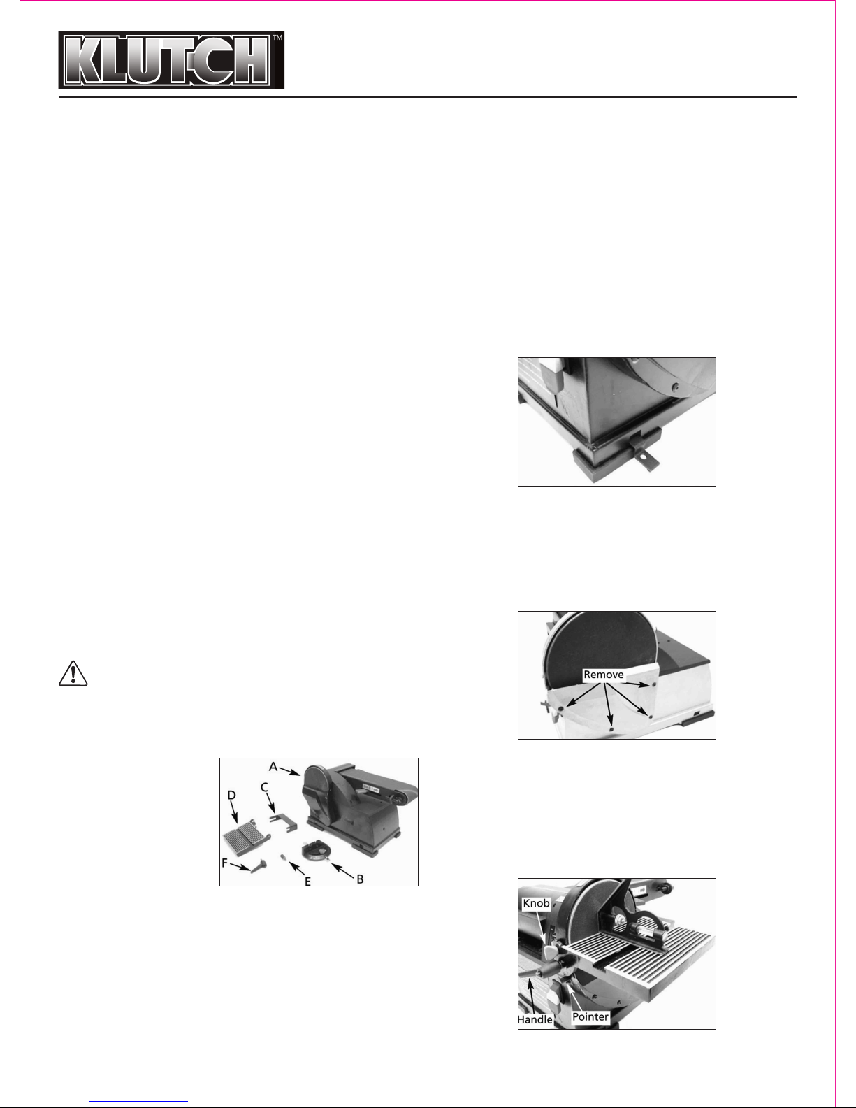
TABLE INSTALLATION
The included table is used with both the disc and belt.
• Position the Table on the Disc Guard and attach it using the
Knobs.
• Thread the Locking Handle through the Table and in to the
Disc Guard.
• Using a combination square, set the table perpendicular to
the Disc and secure in position. If necessary, set the Pointer
at 0º.
 Loading...