


DEAR CUSTOMERS
Congratulations to you to make the right choice. Our devices are
designed and manufactured to meet your expectations and certainly will be
part of the modern-equipped household. We believe that a modern, functional
and practical appliance, made from top quality materials, will meet all your
requirements.
Prior to installation and use of the purchased hood, please read the contents
of this manual, as well as safety rules presented therein. We wish you a lot of
satisfaction from the choice of the hood of our company.
NOTE:
•
During installation, observe the existing regulations for air evacuation.
•
When the chimney hood is used at the same time as appliances
combusting gas or other fuels, the room should be well ventilated. Air
from the hood should not be discharged into the flue duct used to
exhaust the devices combusting gas or other fuels.
•
Before connecting the hood to the power supply, make sure the voltage
and frequency of the supply current corresponds to that given on the
nameplate. The hood must be connected to an easily accessible outlet.
It is unacceptable to remove the plug and permanently connect the
hood to power supply.
•
if cleaning and maintenance is not carried out in accordance with the
instructions, there is a risk of fire.
•
If you use a gas stove, do not leave an open flame.
•
The equipment is not intended for use by persons (including children)
with reduced physical, sensory or mental capabilities.
•
The equipment is not designed for children to play.
•
If the non-detachable supply cord is damaged, it should be replaced by
a special cord or assembly available from the manufacturer or our
customer service.
•
The manufacturer is not liable for failure to comply with regulations for
the installation and maintenance and improper handling of the hood.
Accessible parts may become hot during cooking on the stove.
1. GENERAL INFORMATION
DORMAGEN hood is designed to remove kitchen fumes in an external
venting mode (ducts routed outside) or in a re-circulation mode (internal
circuit). It is designed for mounting above a gas or electric hob. It has an
independent lighting and exhaust turbine, which can be set to one of five
rotation speeds.
NOTE :
Please keep your proof of purchase along with the warranty card stamped for
possible complaints. Without these documents, the warranty is void.
The manufacturer disclaims liability for any damage or injury resulting
from the installation and used not in accordance with instructions contained
herein.
2. SPECIFICATIONS
FEATURES DORMAGEN
Rated voltage 230V-50Hz
Maximum power usage 257 W
Motor power 250 W
Lighting power 4 x 2 W
Max. capacity. 800 m3/h
Appliance class second
Operation continuous, supervised
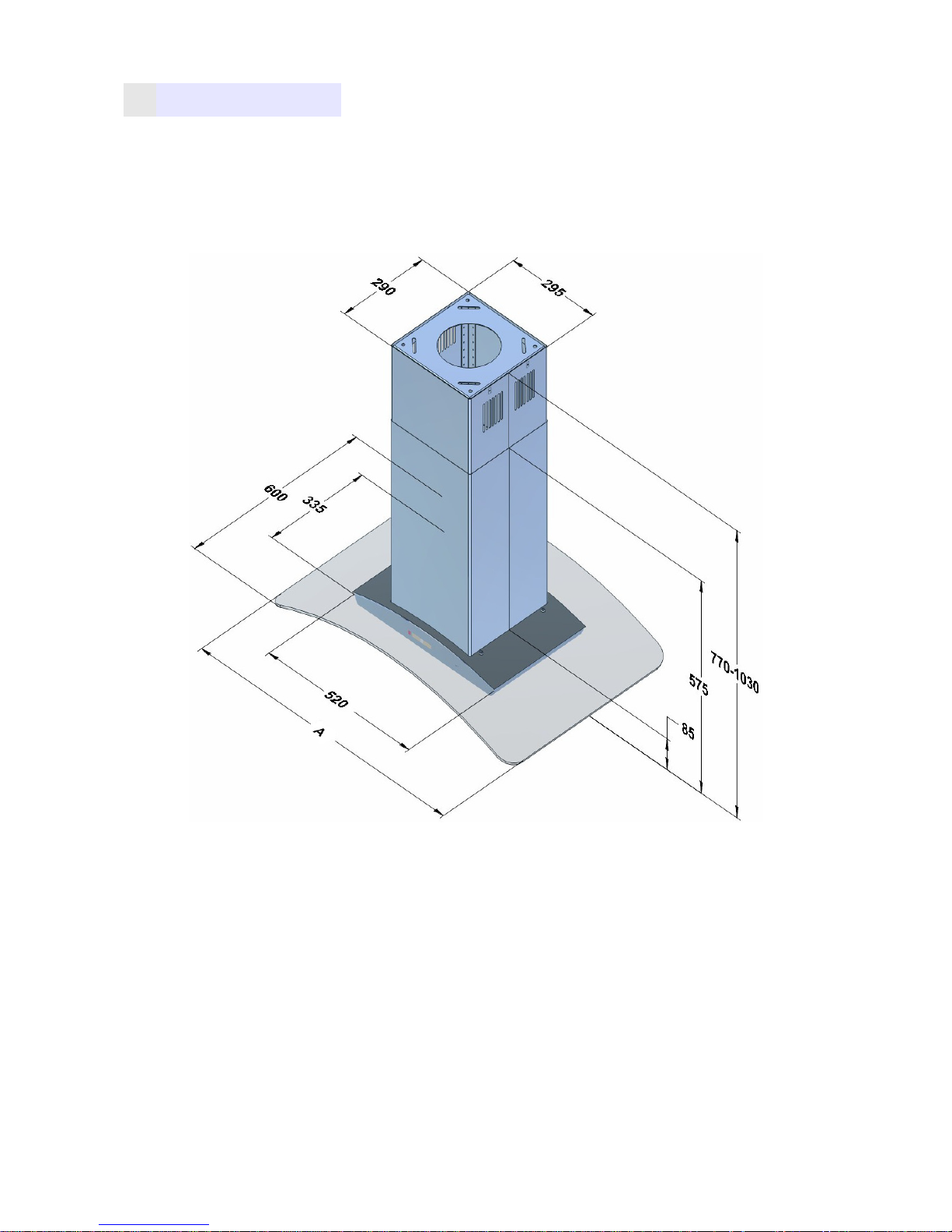
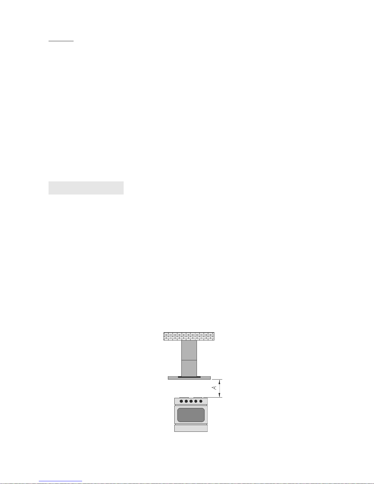
3. DIMENSIONS
DORMAGEN
A - 90
Fig.1
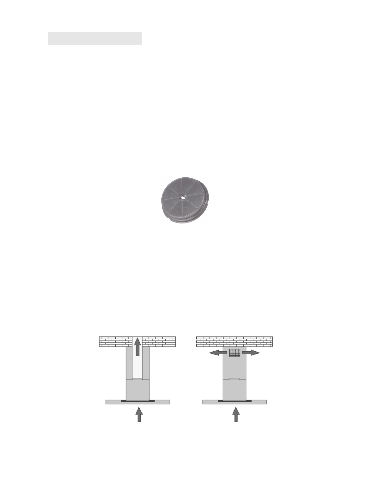
4. INSTALLATION
4.1 SETTING HOOD OPERATION MODE
DORMAGEN hood can operate in two modes:
1.
External venting (Fig.3a) - evacuation of air outside the building by
connecting the hood with the air duct via a rigid plastic tube Ø150mm or
Ø120mm with a reducing union.
2.
Re-circulation (Fig.3b) - internal circulation of air, using carbon filters
(Fig.2).
Fig.2
When the internal circuit is used it is necessary to install the carbon
filters (Fig.2). The air purified through the filters returns into circulation via an
outlet opening.
Carbon filters should be replaced at least once every 3 months (depending on
the intensity of the cooking).
a) EXTERNAL VENTING b) RE-CIRCULATION
Fig.3
NOTE :
The air from the hood should not be discharged into the chimney
channel used to exhaust the appliances combusting gas or other fuels.
4.2 ELECTRICAL CONNECTION
Before connecting the hood to the power supply, make sure the voltage
and frequency of the supply current corresponds to that given on the
nameplate. The hood must be connected to an easily accessible outlet. It is
unacceptable to remove the plug and permanently connect the hood to power
supply. The hood must be connected to the power supply after this assembly.
5. ASSEMBLY
The distance "A" between the lowest part of the chimney hood and a
supporting surface of cooking utensils should be min. 65 cm for a gas stove
(Fig.4).
During assembly, observe the existing regulations for air evacuation.
When the chimney hood is used at the same time as appliances combusting
gas or other fuels, the room should be well ventilated.
In order to achieve optimal air evacuation use a rigid plastic duct with a crosssection Ø150 mm or Ø120mm downstream the reducing union.
Fig. 4

5.1 COMPONENTS FOR ASSEMBLY
1- upper mask (internal)
2- lower mask (external)
3- hood body
4- glass
5- aluminium grease filter
6- ceiling plate
7 – four angles
8 – four dowels 6x60 mm
9 – screws 3,9x6,5 mm
10 – four screws M4x20 with washers
8 9 10
Fig.5
5.2 ASSEMBLY OF ANGLES
Screw the four angles (Figure 7) to the hood body. Each of the angles
should be fastened with at least four screws. The height to which the angles
should be pulled out can be calculated from the relationship, which is shown
in Figure (Fig.7)
6
7
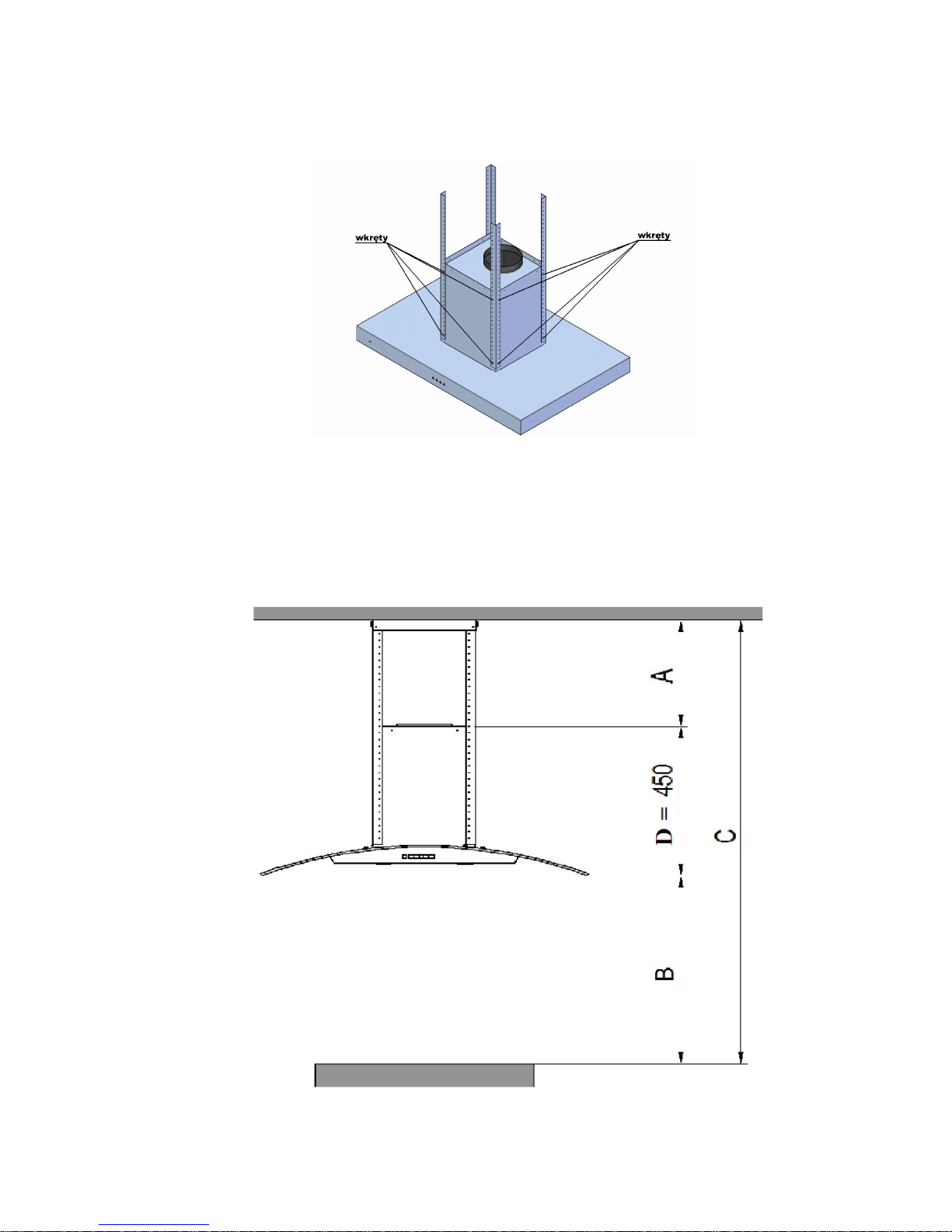
Fig.6
DORMAGEN
Fig.7
A≤C-B -D
where:
A – height to which the angles should be pulled out,
B – distance from the hob to the lower surface of the hood,
C – distance from the ceiling to the hob,
D – distance from the lower surface of the hood to the top surface of the
hood.
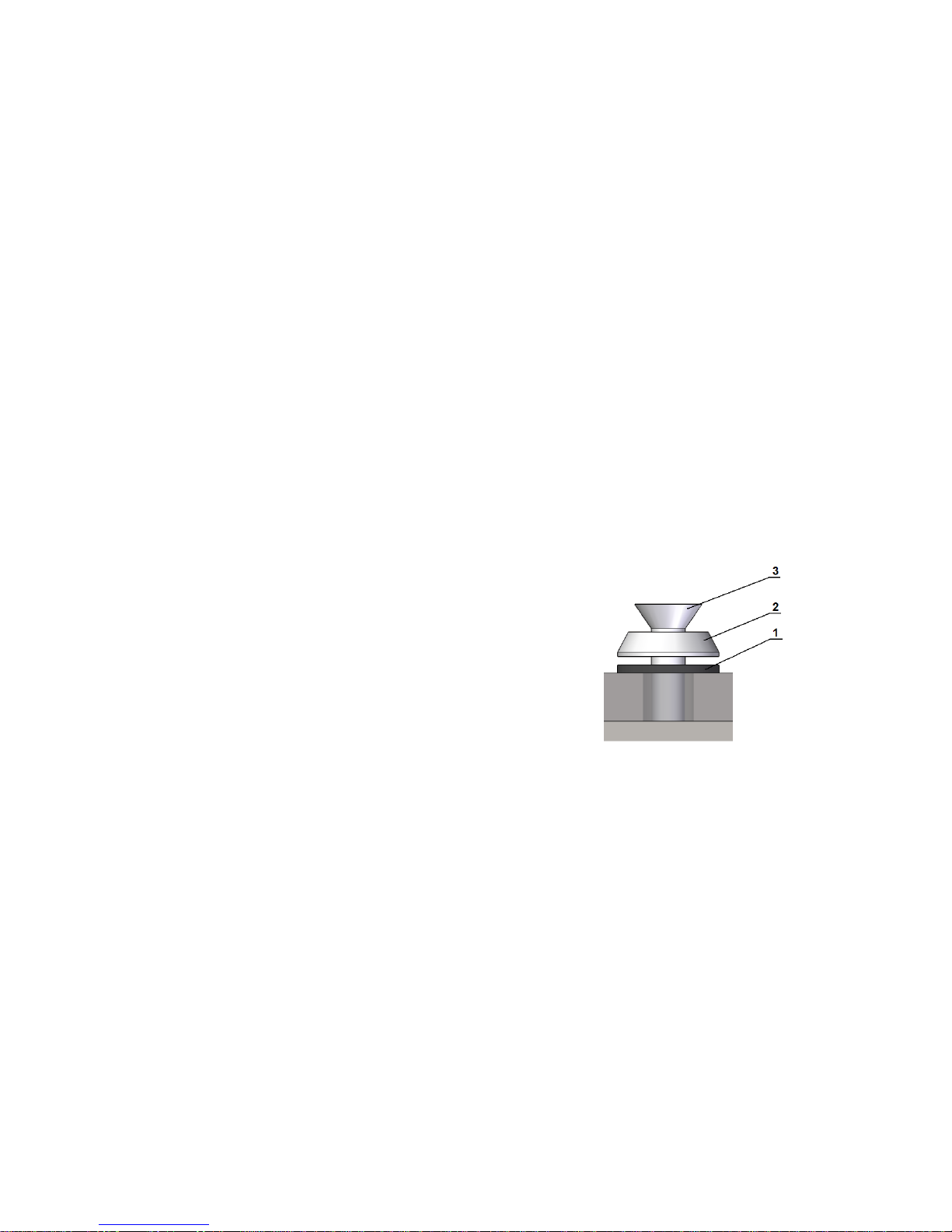
5.3 GLASS ASSEMBLY
Put the glass on the hood body and then
tighten it with the screw (3) M4x20 with
a conical washer (2) and the rubber
washer (1). (Fig.8).
Fig.8
5.4 HOOD TO CEILING ASSEMBLY
Peel off the protective film from the masks. Place the masks on the hood
body with screwed angles and glass in such a way that the inner mask vents
are at the top. Before installation, make sure that the ceiling may transfer the
weight of the hood. Do not mount the hood directly to the plasterboard panels
of suspended ceilings. Clearly indicate the mounting location on the ceiling in
accordance with Figure 9. Spacing of the holes on the ceiling board is
204mm. The holes for fixing dowels should be drilled in the ceiling with φ 8
mm drill. Fix the ceiling board to the ceiling by means of dowels (Note: Be
sure to use steel washers that are provided).
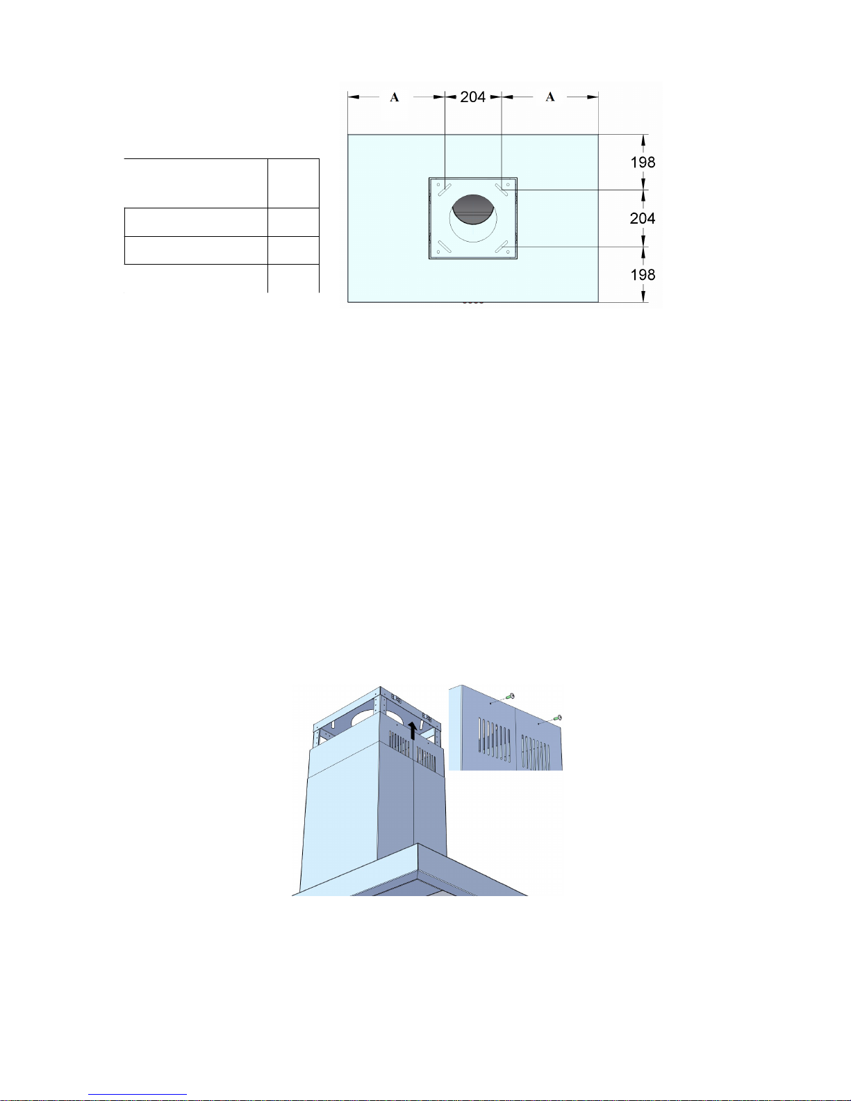
Hood
dimensions
A
60 198
90 348
120 498
Fig.9
Screw the hood to the ceiling plate (this requires great caution, because
the hood has a large mass). Each of the four angles should be fastened with
two screws in such a way that the angles are within the ceiling plate (Fig.10).
If the hood is to operate in a mode of external venting, you must install the
plastic pipe, connecting the hood turbine outlet with a ventilation channel.
Then, the hood must be connected to the mains. The last step is to screw the
inner mask to the ceiling plate (Fig.10).
Fig.10
6. SERVICE
6.1 CONTROL PANEL
DORMAGEN hood is fitted with electronic touch controls with display (Fig.11)
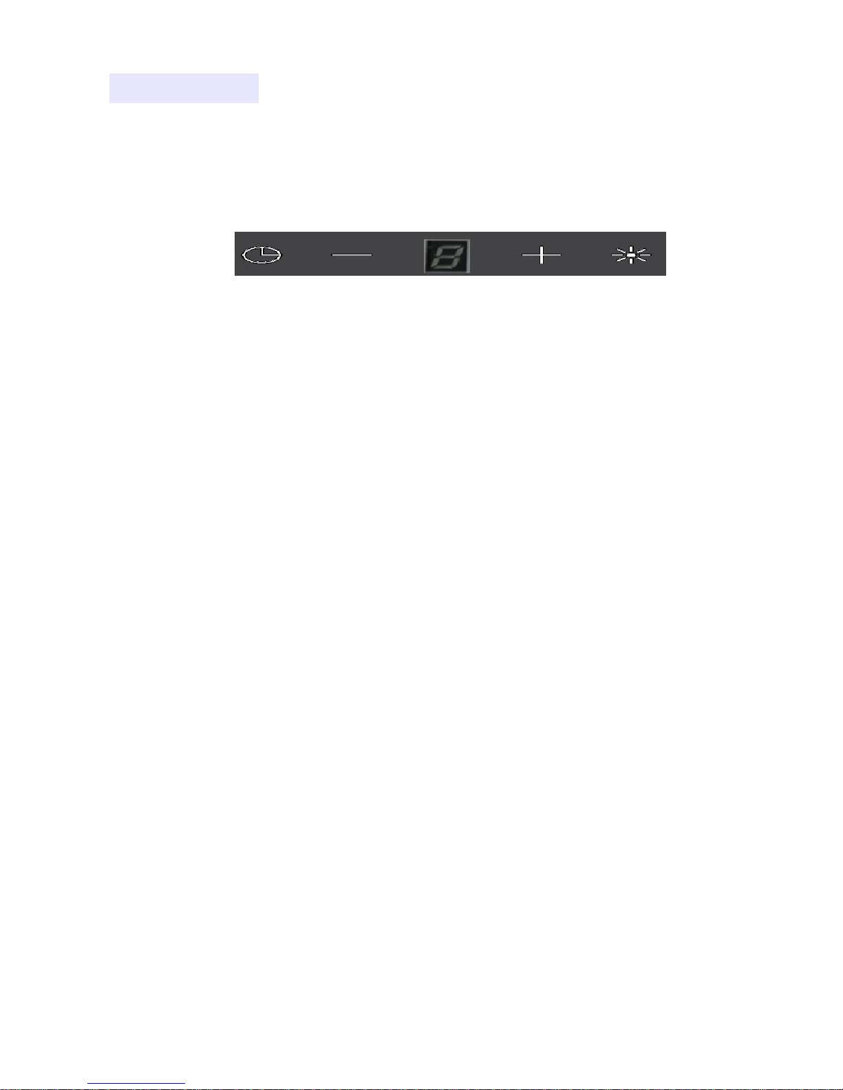
A B C D E
Fig.11
Control (Fig.11):
A – timer
B – minus
C – display
D – plus
E – lighting
1. Turbine operation control
•
PLUS pushbutton allows you to set the next speeds of the turbine (5-
speeds),
•
Holding down the pushbutton PLUS sets the last speed (TURBO
mode),
•
MINUS pushbutton allows you to reduce the set speed up to switching
off the hood,
•
Holding down the pushbutton MINUS switches off the hood,
2. Lighting control
•
LIGHT pushbutton is used to turn on/off the lighting,
3. Hood timer
It is possible to set the time for the hood switching off in the range from ca.
10 min to 60 min.

To do this:
•
Switch on the hood and set the target speed,
•
Press the TIMER button,
•
The digit on the LED display flashes to indicate entering the time
adjustment mode,
•
With TIMER button select the desired switching off delay between 10 and
60 minutes. (The digit "1" = 10 min. "2" = 20 min., etc.)
•
After 2 seconds a dot on the display starts flashing to indicate the timer
operation,
•
After counting down the set delay time the hood and lighting will be
switched off.
4. Locking the touch fields when cleaning the hood glass.
This function is activated by holding down the TIMER field for about 2
seconds
To unlock the keys, hold down the same button.
5. Remote controller
DORMAGEN hood can be controlled via a remote controller.
Fig.12

The definition of buttons (Fig.12)
1 – TIMER
Starts the hood timer,
2 – MINUS
Controls the speed of the turbine down to its deactivation,
3 – PLUS
Turns on the turbine and controls the turbine speed upwards,
4 – LIGHT
Switching on/off the lighting,
Remote controller deactivation function :
1.
Disconnect power supply of the hood.
2.
Reconnect the power to the hood. Upon reconnecting the power to the
hood the function to; enable or disable the remote controller will be
active for 30 seconds.
3. Hold down the pushbutton minus (-) until the display shows the letter r
with a dot (r.)
4. If there is a dot at the letter r (r.) this means that the remote controller is
active and if the letter r is not accompanied by a dot (r) it means that the
remote controller is inactive.
5. Change can be made by pressing the pushbutton plus (+).
6. Save the settings with the light button (☼).
7. After the changes, the hood must be disconnected from the power
supply and then reconnected.
Turbine speeds
The lowest and average speed is used at normal conditions and at low
vapour flow, while the highest rate is used at the large concentration of
kitchen fumes, eg. during frying. It should be noted that the hood should be
activated when you start cooking. This improves the efficiency of the hood
operation.

7. CLEANING AND MAINTENANCE
Regular maintenance and cleaning will ensure good performance
characteristics and reliability, while extending the life of the hood.
Pay particular attention to the grease filters and activated carbon filters, which
should be exchanged in accordance with the manufacturer's
recommendations.
7.1 ALUMINUM FILTER
The grease filter (Fig. 13) must be cleaned depending on the intensity
of cooking at least once a month. To clean the grease filter it should be
removed and washed with warm water with grease-dissolving agents or in the
dishwasher, setting it upright.
When cleaning the grease filter you should pay attention to not damage the
grid. After rinsing and drying, re-install the filter in the hood.
When the aluminium filter is not cleaned on a regular basis, it wears out faster
and the hood loses its capacity.
Fig.13
7.2 CARBON FILTER
In the re-circulation operating mode the carbon filters absorb odours
associated with cooking. The hood is designed to enable the installation of
two carbon filters on both sides of the turbine. The carbon filters are not

suitable for washing or regeneration and should be replaced at least once
every three months, or more frequently in case of intensive use of the hood.
Carbon filter replacement
1. Disconnect the hood from the mains,
2. Remove the grease filters,
3. Remove the carbon filter, which is located inside the hood on the motor
housing, on both its sides (Fig.14), by turning it counterclockwise,
4 Acting inversely to point 3, put a new filter on the motor turbine housing
and turn it around to protect it from slipping.
NOTE:
Always remember to replace both filters at the same time.
Fig.14
7.3 LIGHTING
The lighting system consists of two SMD LEDs with a power of 2w each
(Fig.15).
Fig.15

Halogen bulb replacement
To replace the halogen bulb (Fig.15):
1. Disconnect the hood from the mains,
2. Push the bulb and rotate it about 45 degrees counterclockwise,
4. Remove the worn bulb,
5. Insert the new bulb in reverse order,
7. Connect the hood to the mains.
7.4 CLEANING
Before cleaning, unplug the power cord from the wall outlet socket. For
cleaning the hood from the outside, use a damp cloth with a non-caustic
cleaner. You can use mild detergents such as eg. liquid dishwashing
detergent, glass cleaner.
The agents such as, for example, descaler and fluids for cleaning sanitary
appliances can cause damage to the metal or painted surfaces and void the
warranty.


SEHR GEEHRTE DAMEN UND HERREN!
Sie haben gerade optimale Wahl getroffen. Unsere Vorrichtungen
werden unter Beachtung Ihrer Erwartungen entwickelt und hergestellt und
bestimmt werden einen Teil Ihres modern ausgestattetes Haushaltes
darstellen. Wir sind überzeugt, dass moderne, funktionale und praktische
Vorrichtungen, die aus hochwertigen Materialien hergestellt werden, allen
Ihren Ansprüchen gerecht werden.
Vor dem Beginn mit der Montage und Benutzung einer gekauften
Abzugshaube machen Sie sich bitte gründlich mit dem Inhalt der
vorliegenden Anweisung, als auch der darin enthaltenen
Sicherheitsbestimmungen vertraut. Wir wünschen Ihnen volle Zufriedenheit
hinsichtlich der Auswahl einer Abzugshaube unserer Firma.

WICHTIG:
•
Bei den Montagearbeiten sind geltenden Vorschriften für Luftabfuhr
zu beachten.
• Sollte eine Herdabzugshaube zu gleicher Zeit, wie Vorrichtungen für
Verbrennung von Gas und anderen Kraftstoffen verwendet werden,
soll der Raum entsprechend gelüftet werden.
•
Die Luft von der Abzugshaube ist nicht in einen Kaminkanal
abzuführen, der für Abführung der Abgase aus Vorrichtungen für
Verbrennung von Gas und anderen Kraftstoffen dient.
• Vor dem Anschluss der Abzugshaube an Strom ist zu prüfen, ob
Spannung und Frequenz des versorgenden Stroms den auf dem
Datenschild angegebenen Daten entspricht. Die Abzugshaube soll
an eine einfach zugängliche Steckdose angeschlossen werden.
Entfernung des Steckers und fester Anschluss der Abzugshaube an
Versorgung sind nicht gestattet.
• Sollten Reinigung und Wartung nicht entsprechend der Anweisung
vorgenommen werden, besteht die Brandgefahr.
• Bei dem Gebrauch eines Gasherdes ist offene Flamme ohne
Aufsicht nicht gestattet.
• Die Vorrichtung ist für Benutzung durch Personen (darunter Kinder)
mit beschränkten physischen, sensorischen oder psychischen
Fähigkeiten nicht geeignet.
• Die Vorrichtung ist kein Spielzeug.
• Sollte eine nicht entfernbare Versorgungsleitung beschädigt werden,
soll diese gegen eine spezielle Leitung oder gegen eine Einheit, die
vom Hersteller oder von einem speziellen Reparaturbetrieb zu
beziehen sind, ersetzt werden.
• Der Hersteller trägt keine Verantwortung bei der Nichteinhaltung der
Vorschriften für Einbau und Wartung sowie bei einem nicht
sachgerechten Betrieb der Abzugshaube.
•
Vorhandene Teile können beim Kochen mit dem Herd heiß werden.

1. ALLGEMEINES
WICHTIG:
Halten Sie bitte den Kaufbeleg mit einem, mit Stempel versehenen,
Garantieschein für eine eventuelle Beanstandung. Ohne diese Dokumente ist
die Garantie ungültig.
Der Hersteller haftet nicht für Beschädigungen und Verletzungen, die
infolge der Montage und Benutzung nicht entsprechend der vorliegenden
Gebrauchsanweisung entstanden sind. .
2. SPECIFICATIONS
SPEZIFISCHE
EIGENSCHAFTEN
DORMAGEN
Nennspannung 230V-50Hz
Gesamtleistung 257 W
Motorleistung 250 W
Beleuchtungsleistung 4 x 2 W
Performance, max.
800 m3/h
Gerät der zweiten Klasse
Betriebsart kontinuierlich, unter Aufsicht

3. MAßE
ISLA ZEFIR WK-9
A - 90
Abb.1
4. EINBAU
4.1 BETRIEBSART DER ABZUGSHAUBE
EINSTELLEN
Die Abzugshaube DORMAGEN kann in zwei Betriebsarten betrieben werden:
• Abzug (Abb.3a) - Luftabführung nach außen des Gebäudes durch
21

Verbindung der Abzugshaube mit einem steifen Rohr aus Kunststoff Ø
150 mm mit Lüftungskanal (oder Ø 120 mm mit Verwendung einer
Reduktion).
•
Aufnehmer (Abb.3b) - Innenluftkreis, bei dem Einsatz der Kohlenfilter
(Abb.2).
Abb.2
Bei dem Innenkreis ist der Einbau von Kohlenfiltern notwendig (Abb. 2).
Durch Filter gereinigte Luft kehrt in den Kreis durch die Abfuhröffnung zurück.
Die Kohlenfilter sind nicht seltener als alle 3 Monate (je nach der Intensität
von Kochen) zu ersetzen.
a) ABZUG b) AUFNEHMER
Abb.3
22

WICHTIG:
Die Luft von der Abzugshaube ist nicht in einen Kaminkanal
abzuführen, der für Abführung der Abgase aus Vorrichtungen für Verbrennung
von Gas und anderen Kraftstoffen dient.
4.2 ELEKTROANSCHLUSS
Vor dem Anschluss der Abzugshaube an Strom ist zu prüfen, ob
Spannung und Frequenz des versorgenden Stroms den auf dem Datenschild
angegebenen Daten entspricht. Die Abzugshaube soll an eine einfach
zugängliche Steckdose angeschlossen werden. Entfernung des Steckers und
fester Anschluss der Abzugshaube an Versorgung sind nicht gestattet. Die
Abzugshaube ist an die Versorgung nach der vorliegenden Montage
anzuschließen.
5. MONTAGE
Der Abstand „A” zwischen dem niedrigsten Teil der Herdabzugshaube
und der Fläche für Geschirr für Zubereitung von Gerichten soll mindestens 65
cm für ein Gasherd betragen (Abb.4).
Bei den Montagearbeiten sind geltenden Vorschriften für Luftabfuhr zu
beachten.
Sollte eine Herdabzugshaube zu gleicher Zeit, wie Vorrichtungen für
Verbrennung von Gas und anderen Kraftstoffen verwendet werden, soll der
Raum entsprechend gelüftet werden.
Für Erreichung einer optimalen Luftabführung ist eine steife Leitung aus
Kunststoff mit Querschnitt Ø150 mm oder Ø 120 mm mit dem Einsatz einer
Reduktion zu verwenden.
23

Abb. 4
5.1 BESTANDTEILE FÜR MONTAGE
1- obere Abdeckung (innen)
2- untere Abdeckung (außen)
3- Abzugshaubenkörper
4- Glasscheibe
5- Alu-Fettfilter
6- Deckenplatte
7 - vier Winkel
8 - vier Spreizdübel 6x60 mm
9 – Schrauben 3,9x6,5 mm
10 -vier Schrauben M4x20 mit Unterlegscheiben
24

8 9 10
Abb.5
5.2 WINKEL EINBAUEN
Vier Winkel an den Körper der Abzugshaube anschrauben (Abb. 7). Jeder
der vier Winkel soll mindestens mit vier Schrauben verschraubt werden. Die
Höhe, mit der die Winkel zu verschieben sind, ist aus dem auf der Abbildung
gezeigten Verhältnis zu berechnen (Abb. 7).
Abb.6
25
6
7

DORMAGEN
Abb.7
A≤C-B -D
wo:
A – Höhe, mit der die Winkel zu verschieben sind,
B – Abstand der Küchenplatte von der Unterfläche der Abzugshaube,
C – Abstand von der Decke zur Küchenplatte,
D – Abstand von der Unterfläche der Abzugshaube bis zum Oberfläche der
Abzugshaube.
26

5.3 GLASSCHEIBE EINBAUEN
Die Glasscheibe auf den Körper der Abzugshaube aufsetzen und dann
die mit der Schraube (3) M4x20 mit gelegter
Kegelscheibe (2) und Gummischeibe
(1) verschrauben. (Abb. 8)
Abb.8
5.4 ABZUGSHAUBE AN DER DECKE EINBAUEN
Schutzfolie von Abdeckungen entfernen. Die Abdeckungen auf den Körper
der Abzugshaube mit angeschraubten Winkeln und mit der Glasscheibe so
aufsetzen, dass die Lüftungsöffnungen der Innenabdeckung sich oben
befinden. Vor dem Einbau darauf achten, dass die Decke die durch die
Abzugshaube verursachte Beanspruchung hält. Abzugshaube nicht direkt an
Gipskartonplatten bei den unterhängten Decken einbauen. Montagestellen
auf der Decke präzise entsprechend Abb. 9 markieren. Der Abstand der
Öffnungen auf der Deckenplatte beträgt 204 mm. Öffnungen für Stifte für
Befestigung der Abzugshaube in der Decke mit Bohrer f 8 mm bohren. Mit
den Stiften das Deckenblech an die Decke befestigen (Auf beigefügten
Stahlscheiben achten).
27

Größe der
Abzugshaube
A
60 198
90 348
120 498
Abb.9
Die Abzugshaube an das Deckenblech verschrauben (der Vorgang macht
große Vorsicht notwendig, weil die Abzugshaube großen Gewicht aufweist).
Jeder der vier Winkel soll mit zwei Schrauben so verschraubt werden, dass
die Winkel sich innen des Deckenblechs befinden (Abb. 10). Sollte die
Abzugshaube als ein Abzug betrieben werden, ist ein Rohr aus Kunststoff
einzubauen, das den Auslauf der Abzugsturbine mit Lüftungskanal verbindet.
Anschließend ist die Abzugshaube an die Versorgung anzuschließen. Der
letzte Vorgang ist das Verschrauben der Innenabdeckung an das
Deckenblech (Abb. 10).
Abb.10
6. BEDIENUNG
6.1 BEDIENPANEL
Die Abzugshaube DORMAGEN ist mit elektronischer Touch-Steuerung mit
Display ausgestattet (Abb. 11).
28

A B C D E
Abb.11
Steuerung (Abb.11):
A – Timer
B – Minus
C – Display
D – Plus
E – Beleuchtung
1. Steuerung der Turbine
•Die PLUS-Taste ermöglicht es, nachfolgende Geschwindigkeiten des Abzugs
einzustellen (5 Gänge).
•Sollte die PLUS-Geschwindigkeit gedrückt gehalten werden, wird der letzte
Gang (TURBO-Betrieb) eingestellt.
•Die MINUS-Taste macht es möglich, die eingestellte Geschwindigkeit bis
zum Abschalten des Abzugs zu reduzieren.
•Sollte die MINUS-Taste gedrückt gehalten werden, wird der Abzug
abgeschaltet.
2. Steuerung der Beleuchtung
•Die Taste BELEUCHTUNG dient für Ein- und Ausschalten der Beleuchtung.
3. Zeitschalter der Abzugshaube
Es besteht die Möglichkeit, Abschaltzeit des Abzugs im Bereich von ca. 10
Minuten bis 60 Minuten einzustellen.
Dafür:
•Abzug einschalten und den Zielgang wählen.
29

•Die TIMER-Taste drücken.
•Eine Ziffer auf dem LED-Display pulsiert und signalisiert den Betrieb der
Zeitverstellung.
•Mit der TIMER-Taste eine gewünschte Verzögerungszeit für Abschalten des
Abzugs im Bereich von 10 bis 60 Minuten auswählen. (Ziffer “1” = 10 min. “2”
= 20 min. usw.)
•Nach 2 Sekunden beginnt ein Punkt auf dem Display pulsieren, was auf die
Funktion TIMER hinweist.
•Nach dem Ablauf der eingestellten Verzögerungszeit werden der Abzug und
die Beleuchtung abgeschaltet.
4. Funktion der Sperre von Touchfelder bei der Reinigung der Glasscheibe
von der Abzugshaube.
Diese wird aktiviert, sofern die Taste TIMER circa 2 Sekunden gedrückt
gehalten wird.
Um die Tasten zu entsperren, ist weiter diese Taste zu drücken.
5. Fernbedienung
Die Abzugshaube DORMAGEN kann man mit der Fernbedienung steuern.
Abb.12
30

Definition der Tasten (Abb. 12)
1 – TIMER
Aktivierung des Zeitschalters der Abzugshaube
2 – MINUS
Regulierung der Turbinengeschwindigkeit nach unten, bis zum Abschalten,
3 – PLUS
Einschalten der Turbine und Regulierung der Turbinengeschwindigkeit nach
oben.
4 – BELEUCHTUNG
Ein- und Ausschalten der Beleuchtung;
Fernbedienung ausschalten:
1. Versorgung der Abzugshaube trennen.
2. Versorgung der Abzugshaube wieder anschließen. Nach dem erneuten
Anschließen der Abzugshaube wird die Funktion für Ein- und
Ausschalten der Fernbedienung über 30 Sekunden aktiv.
3. Minus-Taste (-) solange gedrückt halten, bis auf dem Display ein
Buchstabe r mit einem Punkt erscheint (r.)
4. Sollte ein Punkt neben dem Buchstaben r stehen (r.), bedeutet dies,
dass die Fernbedienung aktiv ist; sollte kein Punkt neben des
Buchstabens r stehen (r), bedeutet dies, dass die Fernbedienung nicht
aktiv ist.
5. Änderungen werden mit der Plus-Taste (+) vorgenommen.
6.
Speicherung der Einstellungen erfolgt mit der Beleuchtungstaste (☼).
7. Nach den erfolgten Änderungen ist die Abzugshaube von der
Versorgung zu trennen und dann diese an die Versorgung wieder
anzuschließen.
31

Geschwindigkeit der Turbine
Die niedrigste und die mittlere Geschwindigkeit werden unter üblichen
Bedingungen und bei geringer Dampfstärke verwendet und die höchste
Geschwindigkeit ist bei der hohen Konzentration der Küchendämpfe, z.B.
beim Braten, zu verwenden. Darauf achten, Abzugshaube beim Beginn des
Kochens zu aktivieren. Dies hat einen guten Einfluss auf die Wirksamkeit der
Abzugshaube.
7. REINIGUNG UND WARTUNG
Regelmäßige Wartung und Reinigung stellen gute Nutzeigenschaften
und Zuverlässigkeit sicher und verlängern die Lebensdauer der
Abzugshaube.
Es ist darauf zu achten, dass Fettfilter und Filter mit aktiver Kohle
entsprechend den Empfehlungen ihrer Hersteller ersetzt werden.
7.1 ALU-FILTER
Der Fettfilter (Abb. 13) ist je nach der Intensität von Kochen,
mindestens einmal pro Monat, zu reinigen. Für Reinigung des Fettfilters ist
dieser auszubauen und mit Warmwasser mit Zugabe der Fett lösenden Mittel
zu waschen; alternativ kann man diesen in der Geschirrspülmaschine, mit der
senkrechten Stellung, zu waschen.
Bei der Reinigung des Alu-Filters ist darauf zu achten, dass das Netz nicht
beschädigt wird. Nach dem Spülen und Trocknen ist der Filter in der
Abzugshaube wieder einzubauen.
Sollte der Alufilter nicht regelmäßig gereinigt werden, wird dieser schneller
verbraucht und senkt Performance der Abzugshaube ab.
32

Abb.13
7.2 KOHLENFILTER
In der Aufnehmer-Betriebsart nehmen die Kohlenfilter Kochgeruch auf.
Die Abzugshaube wurde so ausgelegt, dass es möglich ist, zwei Kohlenfilter
auf beiden Seiten der Turbine zu befestigen. Die Kohlenfilter sind für
Waschen nicht geeignet und sollen nicht seltener als alle 3 Monate oder öfter,
wenn die Abzugshaube intensiv benutzt wird, ersetzt werden.
Kohlenfilter ersetzen
1. Abzugshaube von der Versorgung abtrennen.
2. Fettfilter entnehmen.
3. Kohlenfilter, der sich im Innenbereich der Abzugshaube auf dem Gehäuse
des Motors, auf seinen beiden Seiten befindet, entnehmen (Abb. 14),
indem man diesen gegen Uhrzeigersinn dreht.
4.
Umgekehrt als im Pkt. 3: einen neuen Filter auf das Gehäuse der
Motorturbine aufsetzen und für Sicherung gegen Abrutschen diesen
verdrehen.
WICHTIG:
Jeweils darauf achten, die beiden Filter zu gleicher Zeit zu ersetzen.
33

Abb.14
7.3 BELEUCHTUNG
Die Beleuchtungsanlage besteht aus vier LEDs der SMD-Art, je ein mit der
Leistung von 2 W (Abb. 15).
Abb.15
Abb.15
Halogenglühbirne ersetzen
Für Austausch eine Halogenglühbirne (Abb. 15):
1. Abzugshaube von der Versorgung abtrennen.
2. Glühbirne drücken und circa 45º gegen Uhrzeigersinn drehen.
4. Verbrauchte Glühbirne entnehmen.
5. Eine neue Glühbirne einsetzen. Dabei umgekehrt handeln.
7. Abzugshaube an die Versorgung abschließen.
34

7.4 REINIGUNG
Vor der Reinigung ist der Versorgungskabel von der Steckdose
abzutrennen. Für Reinigung der Abzugshaube von außen ist ein feuchtes
Wischtuch mit nicht ätzenden Reinigungsmitteln anzuwenden. Es ist möglich,
milde Reinigungsmittel, wie Spülmittel, Glasreinigungsmittel zu zugeben.
Mittel für Kalkbeseitigung und für Reinigung der Waschräume können
Beschädigung von Metall oder von lackierten Oberflächen und Verlust der
Garantie verursachen.
35

36
 Loading...