

Page 1
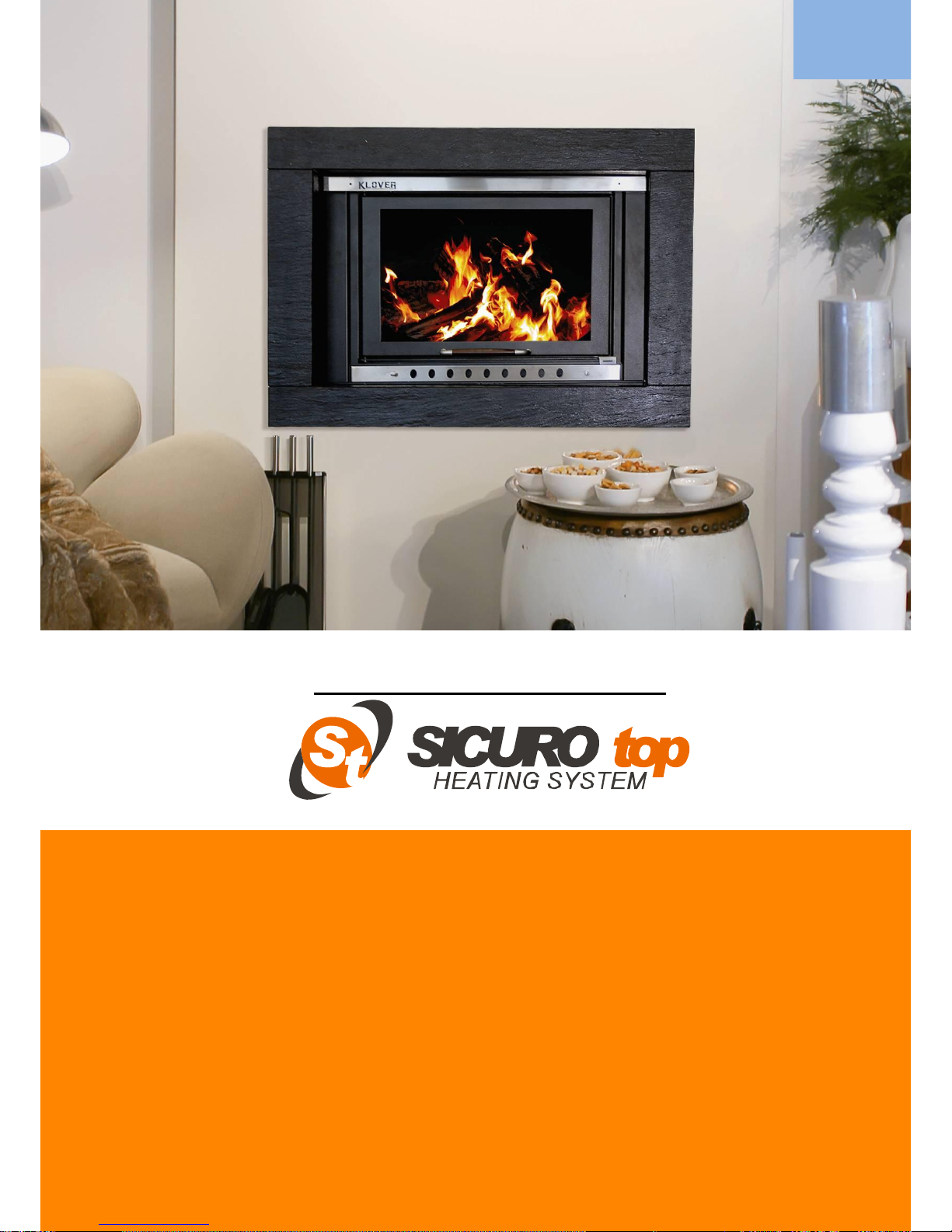
FIREPLACE
HEATING SYSTEM
PATENTED SYSTEM
INSTALLATION
USE AND MAINTENANCE
USEFUL ADVICE
User guide
TKR 35 fireplace heating system
EN
Page 2

2
Page 3

3
Dear Customer,
First of all we would like to thank you for choosing a
“KLOVER” product and we hope you will be satisfied with this product.
Read the warranty guarantee carefully, which is found on the last page of
this User guide; fill the attached warranty card in fully and send it within 10
days from the date of purchase.
We would like to thank you again for trusting KLOVER products and we
also inform you that these models are the result of forty years experience in
the field of construction of solid fuel products.
The manual contains a detailed description of the fireplace heating system
and its functioning, instructions for proper installation, basic maintenance
and control points, which must be periodically performed; furthermore it
contains practical advice which helps to obtain maximum performance from
the fireplace-boiler with minimum fuel consumption.
Enjoy the heat with KLOVER!
Page 4

4
DICHIARAZIONE DI
CONFORMITÀ
DECLARATION OF
CONFORMITY
In accordo con la Direttiva 89/106/CEE (Prodotti da Costruzione), la Direttiva 2006/95/CEE (Bassa Tensione) e la Direttiva
2004/108/CEE (Compatibilità Elettromagnetica).
According to the Directive 89/106/EEC (Construction Products ), the Directive 2006/95/EEC (Low Voltage) and the Directive
89/336/EEC (Electromagnetic Compatibility).
N° di identificazione - Identification No. :
TKR-01
Emesso da - Issued by :
KLOVER s.r.l.
Via A. Volta, 8
37047 San Bonifacio (VR)
Tipo di apparecchio - Type of equipment :
Solid fuel closed fireplaces
Marchio commerciale -Trademark :
KLOVER
Modello o tipo - Model or type :
SP35 – KTP35 – XP35 – TKR35
Uso - Use
:
Domestic heating
Costruttore - Manufacturer
:
KLOVER s.r.l.
Via A. Volta, 8
37047 San Bonifacio (VR)
Ente notificato - Notified body
:
NB 1881
IMQprimacontrol S.R.L.
I - 31020 Zoppè – San Vendemmiano (TV)
Via dell’Industria, 55
Le norme armonizzate o le specifiche tecniche (designazioni) che sono state applicate in accordo con le regole della buona arte
in materia di sicurezza in vigore nella CEE sono:
The following harmonised standards or technical specifications (designations) which comply with good engineering practice in
safety matters in force within the EEC have been applied:
Norme o altri riferimenti normative
Standards or other normative documents
Rapporto di Prova ITT
Initial Type Tests Report
EN 13229
CPD-08-048
EN 60335-1
EN 50165
EN 55014-1
EN 61000-3-2
EN 61000-3-3
EN 55014-2
In qualità di costruttore e/o rappresentante autorizzato della società all‟interno della CEE, si dichiara sotto la propria
responsabilità che gli apparecchi sono conformi alle esigenze essenziali previste dalle Direttive su menzionate.
As the manufacturer’s authorised representative established within EEC, we declare under out sole responsibility that the
equipment follows the provisions of the Directives stated above.
San Bonifacio (VR), 19.09.08
Muraro Mario
Chairman of the Board
Page 5

5
FIREPLACE
HEATING
SYSTEMS
mod. TKR 35
S.R.L.
Page 6

6
Copyright
All rights reserved. The reproduction of any part of this manual, in any form,
without the explicit written permission of KLOVER srl is forbidden. The content of
this manual can be modified without forewarning. Although we have carefully
collected and verified the documentation contained in this manual, KLOVER srl
cannot be held liable for how you utilise it.
Copyright © 2002 KLOVER srl
Latest revision: December 2010
Page 7

7
GENERAL INDEX
Introduction…………………………………………………………... 9
Important safety instructions…………………………………………….. 9
Some precautions…………………………………………………………. 10
Conventions used in the manual………………………………………… 10
Technical data…………..…………………………………………… 11
Dimensions of the fireplace heating system.…………………………... 11
Hydraulic connections...................………………………………………. 12
Technical features……………………………………………..………….. 13
Assembly..……………………………………………………………. 14
Positioning………..………………………………………………………... 14
Air vent……………………………………………………………………... 15
Flue and connection to the same ……………………………….……… 17
Chimney……………………………………………………………………. 19
Connections………………………………………………………….. 20
Electric connections………………….…………………………………… 20
Electric control unit……………………………………………………….. 21
Control of any 3-way valve for the DHW circuit……………………….. 27
Control of any coupled boiler……………………………………………. 28
Example of electrical connection…………………………………………29
Hydraulic connection……………………………………………………… 31
Example of fireplace heating system – boiler connection…………….. 32
Example of fireplace heating system connection only………………… 33
Fireplace heating system covering………...……………………. 34
Commissioning……………………………………………………… 36
Filling the system for the first time……………………………………… 36
Filling the fireplace heating system……………………………………… 37
Ignition……………………………………………………………………… 38
Boiling………………………………………………………………………. 39
Anti-freeze protection…………………………………………………….. 39
Functioning principle……………………………………………………… 39
Maintenance………………………………………………………….. 40
Cleaning the boiler body…………………………………………………. 40
Cleaning the ceramic glass………………………………………………. 41
Cleaning the flue………………………………………………………….. 42
Page 8

8
Maintenance of the boiler body………………………………………….. 43
The wood to burn……...……………………………………………. 44
Wood features…………………………………………………………….. 44
Troubleshooting……………………………………………………... 47
Useful advice…………………………………………………………. 49
Warranty certificate…………………………………………………. 50
Page 9

9
INTRODUCTION
Important security instructions
Read these instructions before installing and using the product.
Fireplace heating system installation and commissioning must
be performed by skilled staff aware of the importance of
respecting the Safety Standards in force. They will be
responsible for the definitive installation of the machinery and
its consequent proper functioning.
KLOVER srl will not be held responsible if these precautions are
not respected.
During installation of the appliance all local regulations,
included those referring to National and European Standards,
must be followed.
Connect the product flue gas outlet to a flue that has the features
given in the Assembly section in this user guide.
The appliance is not suitable for the installation on a shared flue
system.
If the flue should catch fire, you must be provided with appropriate
systems for damping down the fire or call the fire service.
Connect the product to sockets with earth. Avoid using sockets
controlled by switches or automatic timers.
Do not use a damaged or worn power supply cable.
If a multiple socket is used, make sure that the total voltage of the
connected devices does not exceed that supported by the socket.
Furthermore make sure that the total voltage of all these devices
connected to the socket does not exceed the maximum level
accepted.
Do not use flammable substances to clean the appliance and its
elements.
Do not leave containers and flammable substance in the place where
the fireplace heating system is installed.
Do not use the appliance as an incinerator or in any other way
different to that for which it has been designed.
Do not use fuels different to those which are recommended
Do not use liquid fuels
The external surfaces of the appliance reach high temperatures when
it is running; operate with caution in order to avoid burns.
Page 10
10
Only use original spare parts recommended by the manufacturer.
Do not perform any unauthorised modification to the appliance.
Some Precautions
Do not touch the hot components of the fireplace heating
system(ceramic glass, loading door) during normal functioning
Use the appropriate luminous button to switch the electrical panel off.
Do not disconnect the power supply cable while the fireplace heating
system is running.
Keep children away from the fireplace heating system when it is
running since they could get burned by touching its hot components.
Children and inexperienced people are not allowed to use the
appliance
Conventions used in the manual
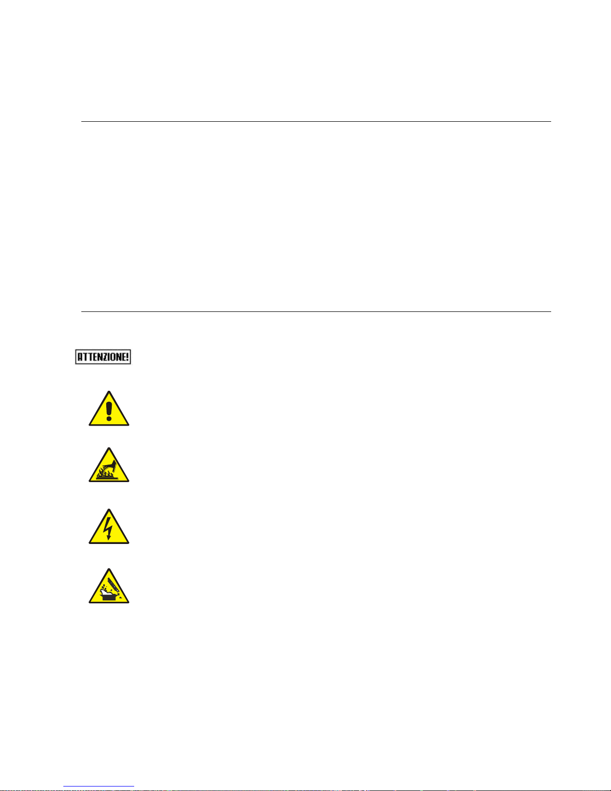
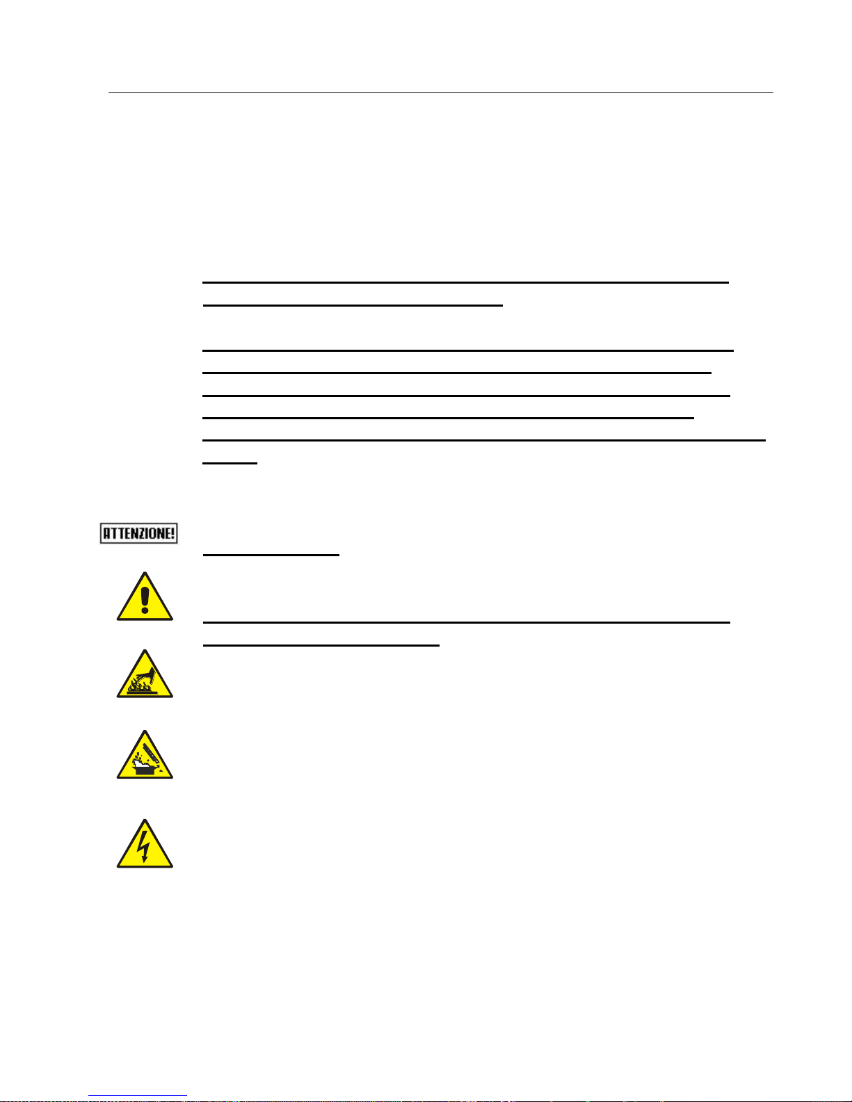
Danger due to fireplace heating system functionality
General danger for personal safety.
Danger for people and objects due to materials at high
temperatures.
Danger for people and objects due to electric power.
Burns hazard for persons due to hot, pressurised liquids (with
temperature not exceeding that of boiling point at atmospheric
pressure).
Page 11
11
TECHNICAL DATA
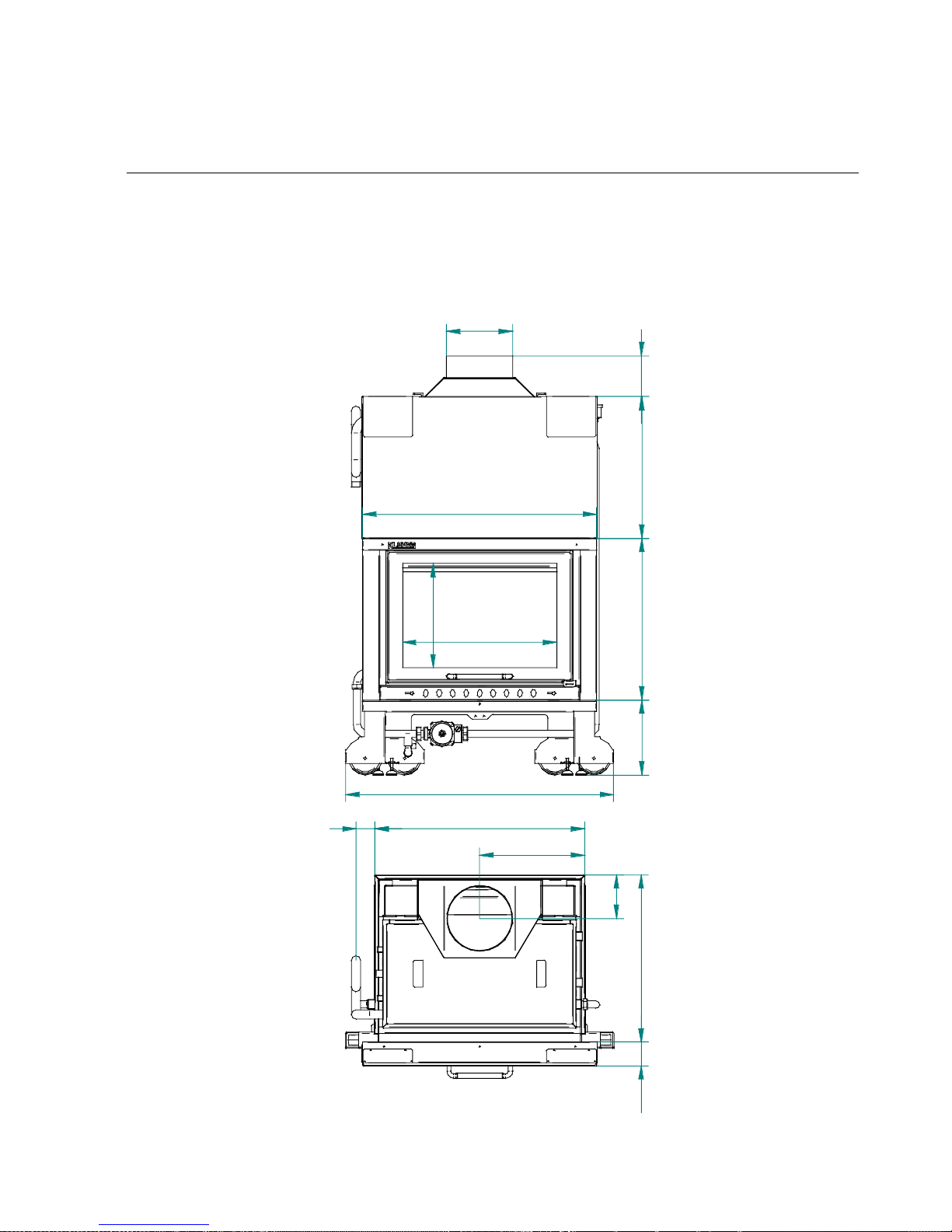
Dimensions of the fireplace heating system
Here below are the fundamental views of the fireplace heating system
(front view and view from above) useful to check clearance and
detailed dimensions.
573
388
870
599
526
245
620,5
87,5
997
278
150
390
161,5
78069
Page 12
12
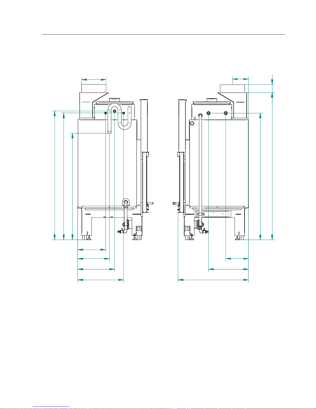
Hydraulic connections
LEFT SIDE RIGHT SIDE
R M
S
P
T
F
C
K
1473
80
1268
228
400
704
277,5
317,5
367,5
457,5
1067
1268
1288
161,5
245
M = SYSTEM FLOW 1” M GAS
R = SYSTEM RETURN 1” M GAS
S = BOILER DRAIN WITH COCK
P = CONTROL UNIT BULBS POCKET
F = DOMESTIC COLD WATER INLET (on prepared models only) 1/2" M GAS
C = DOMESTIC HOT WATER OUTLET (on prepared models only) 1/2” M GAS
K = BOILER BODY LOADING 1/2" M GAS
T = BOILING VENT VALVE 1” M GAS
FLUE EXHAUST 250mm M
Page 13

13
Technical features
Nominal heat output
kW (Kcal/h)
34,5 (29.700)
Nominal heat output
kW (Kcal/h)
28,5 (24.500)
Heat output yield for heating water
kW (Kcal/h)
17 (14.600)
Heat output yield in the environment due to radiation
kW (Kcal/h)
11,5 (9.900)
Yield % 83
Nominal capacity
Watt
88
Nominal voltage
V
220
Nominal frequency
Hz
50
Expansion vessel lt/preloading bar
6 / 1
Maximum working pressure/recommended
bar
2,5 / 1,5
CO at 13% of oxygen
%
0,24
Minimum chimney effect
Pa
11
Combustion gas flow
g/s
25,3
Flue gas outlet temperature
°C
216
Hourly consumption of wood
Kg/h
7,2
Wood loading interval
min
60
FLOW/RETURN heating hydraulic connections
Ø
1” M GAS
Boiler body capacity
litres
110
Width (exposed part)
mm
870
Height (exposed part)
mm
600
Depth
mm
710
Minimum safety distance from flammable materials
mm
180
Weight
Kg
350
The data reported above is approximate and not binding. The manufacturer reserves the faculty
to make any modifications to the product in order to improve its performance.
The given heat power can change according to the wood used.
The consumption of wood is subject to the quality and degree of dryness of the same
Page 14

14
ASSEMBLY
Positioning
The initial phase for the best installation of the fireplace heating
system is to determine its optimal location; regarding this the
following data needs to be taken into account:
Possibility of creating an external air vent;
Possibility of creating a straight flue and possibly coaxial at
the fireplace heating system outlet;
Possibility of creating piping necessary to discharge
boiling;
Proximity to the main liquid collector and /or the boiler if
one already exists);
Proximity or ease of connection to the water system.
Once the best location for the appliance is determined, it is
possible to position the fireplace heating system following the
indications below.
The appliance must be installed on a floor with suitable load
capacity. If the existing building does not fulfil this requirement
appropriate measures (e.g. load distribution plate) must be
taken.
The minimum safety distance from inflammable materials must
be at least 300 mm from the fireplace heating system.
Appliance installation must guarantee easy access for cleaning
the appliance itself, the gas pipes and the flue.
The air extraction devices must not be used in the same room as
the appliance, unless an adequate ventilation air supply is
envisioned.
Page 15

15
Air vent
Modern houses are all equipped with hermetic fittings, which do
not allow any air to pass.
To burn one Kg of wood about 15 m3 of air is required (in
fireplaces with closed hearth) and 40 m3 in fireplaces with open
hearth.
If the combustion of the wood inside the combustion chamber is
perfect, the amount of carbon dioxide (CO2) produced will be
equal to that absorbed by a living plant via the “chlorophyll
photosynthesis” process.
The lack of oxygen leads to bad and incomplete combustion,
which only makes partial use of the wood's energy and instead
of developing carbon dioxide (CO2) causes the formation of
carbon monoxide (CO), a highly toxic substance. Consequently
it heats less and pollutes more.
This is why fireplace absolutely require an external air vent.
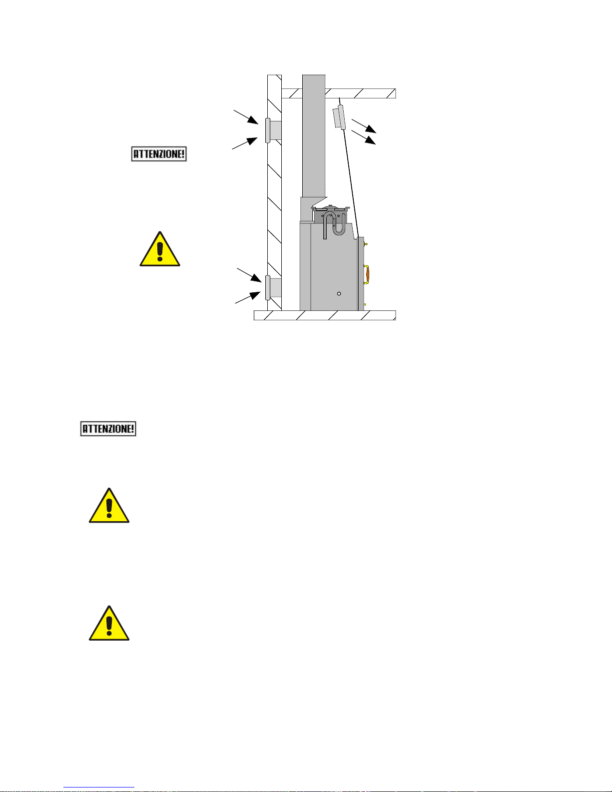
To realise the air vent in the wall behind the fireplace heating
system, follow the indications given below:
IMPORTANT:
Make an external air vent respecting the following minimum
passages:
Solution A: 650 cm2 (Ø 30 cm)
Solution B: 390 cm2 (Ø 22 cm)
It is also mandatory to create a hood aeration grid "C" with
minimum passages, 390 cm2 (Ø 22 cm), without filters or
closures;
Page 16
16
SFIATO
S
F
C
K
TST
SFIATO
F
C
K
B
A
C
N.B.: It is important that the grid communicates with the external
air vent without connection via pipes.
If it is not possible to realise the air vent in the wall behind the
fireplace heating system, make the hole in a perimeter wall where the
fireplace heating system is installed.
If it not possible to realise the external air vent in the same room
where the fireplace heating system is installed, this hole can be made
in an adjoining room as long as this room communicates
permanently, by means of a transit hole (20cm minimum diameter).
The UNI 10683 Standard PROHIBITS the withdrawal of
combustion air from garages, combustible material warehouses,
or from activities where there is a fire hazard.
If there are other heating or suction appliances in the room, air
vents must guarantee an air volume necessary for the proper
functioning of all devices.
Only sealed appliances (e.g. C type gas appliances, according to
the UNI 7129 Standard) or appliances that do not cause a lower
pressure compared with the external environment can pre-exist
or be installed in the place where the fireplace heating system
must be installed.
Extractor fans can cause functioning problems to the thermo stove when
they are installed in the same room or space where the fireplace heating
system is found.
Page 17

17
Flue and connection to the same
The Flue is a fundamental component for correct functioning of the
fireplace heating system. The minimum section of the flue must be that
indicated in the fireplace heating system technical features (250 mm).
Each fireplace heating system must be equipped with its own flue,
without other intakes (boilers, fireplaces, stoves, etc…). Flue
dimensions are closely related to its height, which must be measured
from the fireplace heating system flue gas outlet to the chimney base.
In order to guarantee draught, the chimney flue outlet surface must be
twice as big as the flue section. The combustion products exhaust
pipe, generated by the natural draught appliance, must respond to the
following requisites:
Combustion products sealed, waterproof and suitably isolated
and insulated in the same way as the conditions of use (cf UNI
9615);
Realised with suitable materials in order to resist to normal
mechanical stress, heat, action of the combustion products
and in the event of condensation;
Upward alignment after the vertical tract throughout the
remaining pathway with 50% minimum gradient. The subhorizontal alignment part must not have a length greater than
¼ of the effective height of the flue or chimney and it must not
however be longer than 2,000 mm;
Preferably circular internal section: squared and rectangular
sections must have rounded angles with radius larger than 20
mm;
Constant, free and independent internal section;
Rectangular sections with 1:5 maximum ratio between the
sides;
If the flue is installed externally it is absolutely necessary
that it is insulated in order to avoid the flue gas cooling
and the formation of condensate;
For the assembly of the flue gas pipes (which go from the
appliance to the flue inlet) elements of non-combustible
material must be used, which are suitable for resisting
combustion products and their condensation;
It is forbidden to utilise fibre cement pipes to connect the
appliances to the flue;
Page 18

18
Flue pipes must not pass through places in which the
installation of combustion appliances is forbidden;
The assembly of flue pipes must be performed in a way to
guarantee the sealing against flue gas for the appliance
functioning conditions in low pressure;
The assembly of horizontal tracts is prohibited, unless
absolutely necessary;
It is forbidden to use tilted elements;
The flue gas pipe must allow the recovery of soot or be
cleanable and must have a constant section;
It is prohibited to make other air intake channels and pipes, for
plant engineering, transit inside the flue gas pipes, even if
over-dimensioned.
Page 19
19
Chimney
The chimney is a device crowning the flue, used to ease dispersion of
combustion products.
It must satisfy the following requisites:
Have a useful outlet section that is not less than the double
of that of the flue on which it is inserted;
Be conformed in a way to prevent the penetration of rain
and snow into the flue;
Be built in a way that, also in the case of winds from every
direction and inclination, to ensure combustion exhaust.
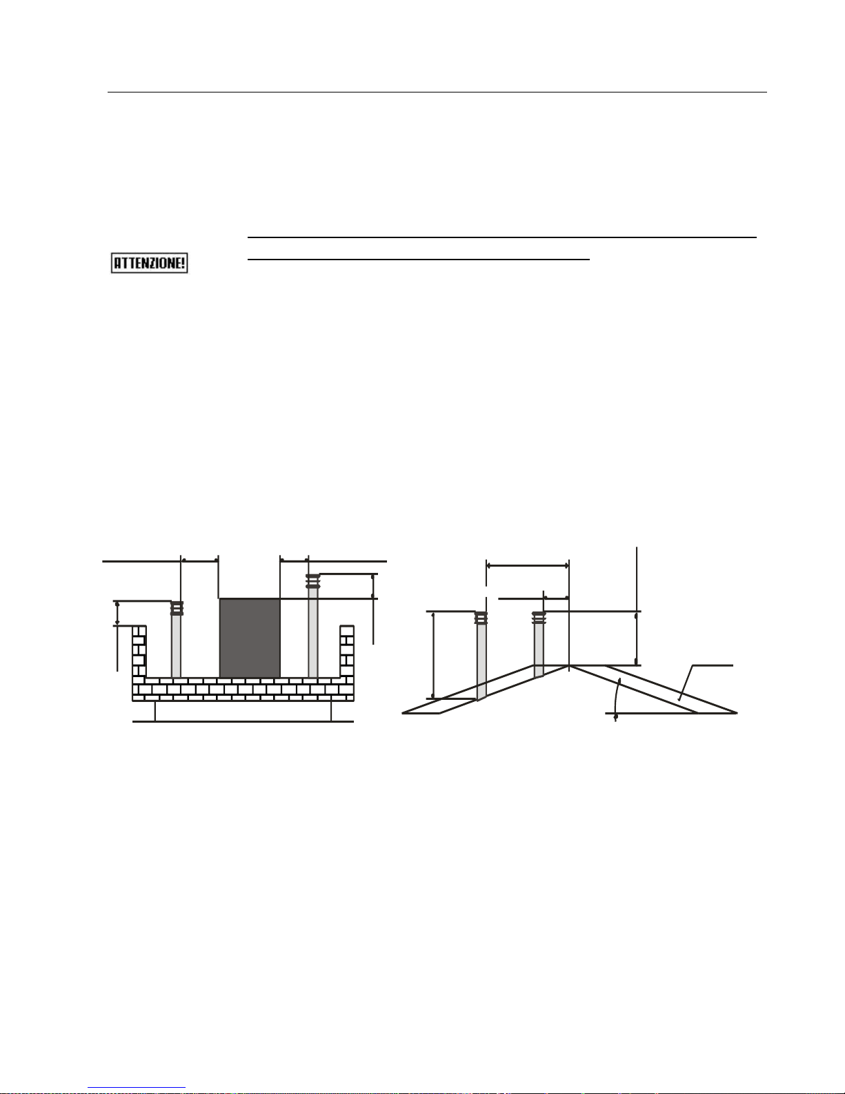
The outlet height (where height means that which corresponds to the
top of the flue, independently of any chimneys) must be outside of the
so-called reflow zone in order to prevent the formation of counterpressures, which prevent free exhaust of the combustion products into
the atmosphere.
It is therefore necessary that the minimum heights, indicated in the
following figures, are respected:
Technical
volume
0,5 m
0,5 m
Distance > 5 m
Distance < 5 m
Distance> 1,85 m
Distance< 1,85 m
0,5 m over
the ridge
Reflow zone
1m minimum
15°
Page 20

20
CONNECTIONS
Electrical connection
The electric connection must only be performed by qualified
staff, with respect to general and local Safety Standards in
force.
Check that the power supply voltage and frequency
correspond to 220 V – 50 Hz.
Appliance safety is obtained when the same is correctly
connected to an efficient earth plant.
In the electric connection to the mains power supply, envision a 6
A – Id 30 mA differential magnet circuit breaker switch with
relevant breaking load. The electric connections, including the
earth, must be made after the voltage has been removed from
the electric plant. When realising the system remember that the
cables must be placed in an unmovable and away from parts
subject to high temperatures. During the final wiring of the circuit,
only use components with a suitable electric protection rating.
KLOVER srl declines all responsibility for injury to persons,
animals or damage to objects deriving from the failure to
connect the network to the fireplace heating system earth
plant and failure to comply with the IEC Standards.
Page 21

21
Electric control unit
The electric control unit (supplied with the fireplace heating
system on request) is used to control and command the start-up
of the pump and any motorised 3-way valves.
It is composed of:
master switch (used to supply power to the control unit
itself);
pump adjustable thermostat (used to activate or
deactivate the pump on reaching, or not, the temperature
we set on the thermostat itself);
valve adjustable thermostat (used to exchange any
motorised valve on reaching, or not, the temperature we set
on the thermostat itself. It is normally used for the DHW
connection with coupling to another boiler);
aux thermostat (used to control any service associated
boiler);
service thermostat (used to activate or deactivate the
circulation pump on reaching, or not, the temperature we
set on the thermostat itself);
thermometer (indicates the temperature of the water inside
the fireplace heating system);
acoustic alarm (it activates whenever the water of the
body-boiler reaches and exceeds the temperature of 90-
95°C);
For the connection to the control unit, consult the layout
inside the box of the same.
The control unit has an internal fuse T 3,15A.
Page 22
22
4
2
Set
1 3 4
POMPA
VALVOLA
AUX
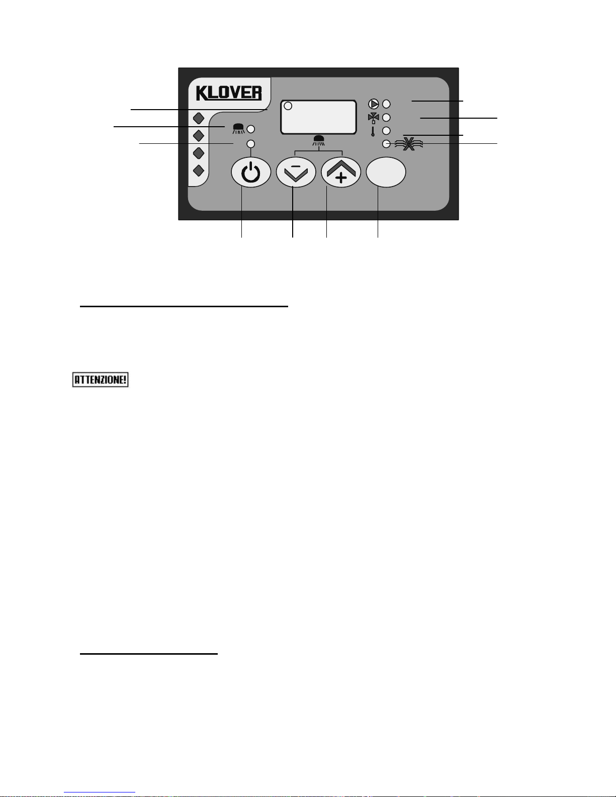
DESCRIPTION OF THE KEYS
P1 ON/OFF the button, pressed for two consecutive seconds,
allows manual switch-on/off of the control unit depending on whether it
is respectively off or on.
During the normal operation of the fireplace the control unit must
ALWAYS be turned on.
P2 DECREASE TEMPERATURE allows to decrease the value of
the thermostat indicating the minimum water temperature of the boiler
to turn on the pump, switch any 3-way motorized valve to control an
associated boiler and to turn on the circulation pump.
P3 INCREASE TEMPERATURE allows to increase the value of
the thermostat indicating the minimum water temperature of the boiler
to turn on the pump, switch any 3-way motorized valve to control an
associated boiler and to turn on the circulation pump.
P4 SET/MENU provides access to the set thermostat values
reported by the associated PUMP / VALVE / AUX / SERV flashing
LED.
It also allows to save changes made to the values of each thermostat.
LED DESCRIPTION
L1 PUMP LED The LED is on when the pump thermostat
has been selected.
L2 VALVE LED The LED is on when the valve thermostat
has been selected.
P1
P2
P3
P4
L5
L1
L2
L3
L4
L6
L7
Page 23
23
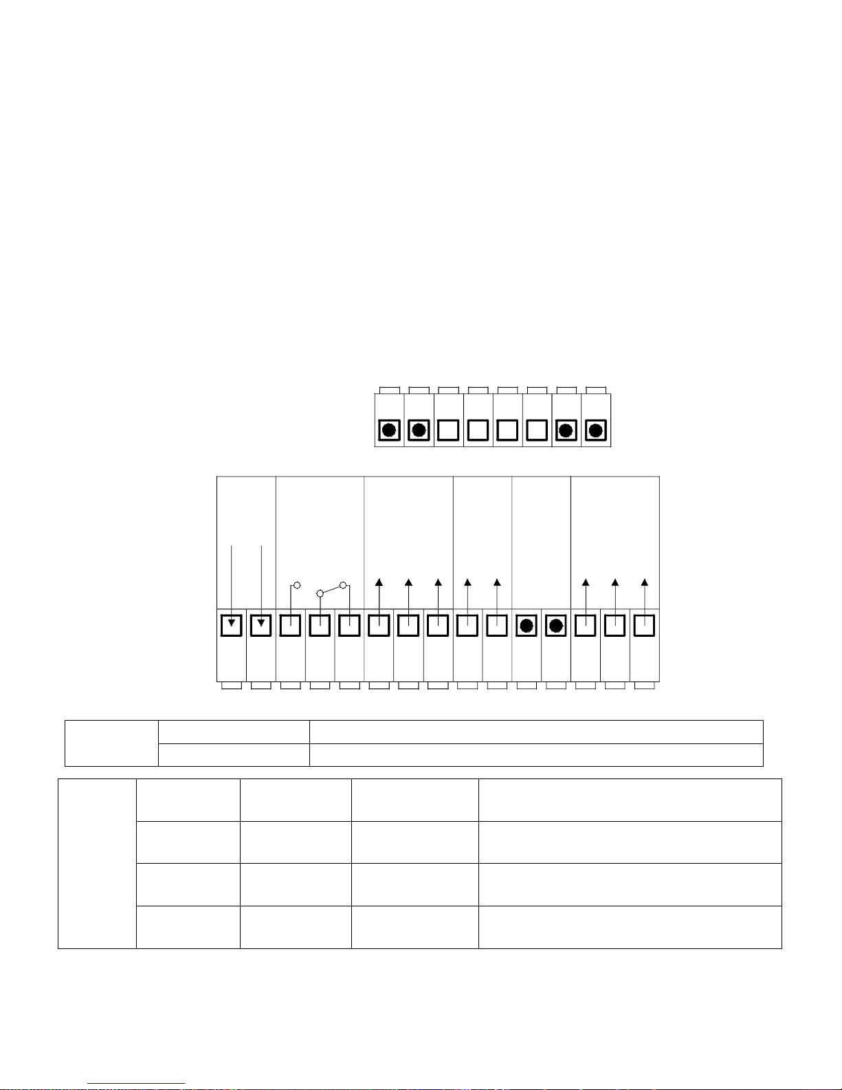
L3 AUX LED The LED is on when the auxiliary thermostat
has been selected.
L4 LEVEL SWITCH LED The LED is on when there is no water
inside the tray or not enough
water.
L5 OFF LED The LED is on when the control unit
is off.
L6 DHW LED The LED is on when the dhw function
is active.
L7 SERV LED The LED is on when the service thermostat
has been selected.
LINEA
230 Vac
POM PA
230 Vac
VALVOLA
230 Vac
AUX
1
2
3
4
5
6
7
8
9
10 11
12 13 14
N L
LON
LON
LON
LOFF
NO
COM
NC
23 22 21
2019 18
LIVEL.
SONDA
15
LOFF
1716
N
N
N
SERV
230 Vac
Inputs
PROBE
Water Probe: Temperature Range 0 – 100 °C
H2O LEVEL
ON/OFF consent: Level switch
Outputs
PUMP
System
pump:
230 Vac
power supply
Clamps 13(FON) - 14(N) - 15(FOFF)
SERV
Service:
230 Vac
power supply
Clamps 9(FON) - 10(N)
VALVE
Valve:
230 Vac
power supply
Clamps 6(FON) - 7(N) - 8(FOFF)
AUX
Auxiliary:
Free
contacts
Clamps 3(NO) - 4(COM) - 5(NC)
Page 24

24
FUNCTIONS
1- ON/OFF:
The control unit is switched on/off by pressing and holding the P1 (ON/OFF)
The OFF status is signalled by the fact that the L5 LED turns on.
2- SAFETY function:
If the temperature detected by the PROBE exceeds the value of the Safety
Thermostat,
this forces the activation of the PUMP.
3- ALARM function:
If the temperature detected by the PROBE exceeds the value of the Alarm
Thermostat,
this activates the acoustic and visual signal.
SILENCE: by pressing any button, the acoustic signal is deactivated
for 5 minutes.
4- NO ICE function:
If the temperature detected by the PROBE goes below the value of the
ANTI-FREEZE Thermostat,
this activates the timed PUMP outlet.
The relative L1 LED turns on and ICE starts flashing on the display.
5- PUMP ANTI-LOCKING programme:
In the event of inactivity of the PUMP outlet for more longer than the
ANTILOCKING Timer,
this activates the outlet of the PUMP.
The relative L1 LED turns on and bLP appears on the display.
6- SECURE TEMP function:
If the device is OFF and in SAFE conditions,
the device automatically positions itself in the ON status.
7- LEVEL SWITCH function:
The closure of the input closure determines the activation of the L4 LED.
8- OUTPUTS function:
PUMP ON: for a temperature above the PUMP thermostat
for a temperature above the ALARM thermostat
for a temperature below the ANTI-FREEZE thermostat
VALVE ON: for a temperature above the VALVE Thermostat
AUX ON: for a temperature above the AUX Thermostat
Page 25

25
SERV ON: for a temperature above the SERVE thermostat
9- DHW function:
By holding down the P2 (-) and P3 (+) buttons at the same time it is possible
to activate the DHW function. At this point, while the L6 LED flashes, just set
the time (in minutes) for which you want to have all the heat burned for the
production of domestic hot water. By activating this function, the pump turns
off and remains off until the minutes set on this function have elapsed. When
this function is active, the pump will turn on only when you reach the safety
temperature of 85 ° C. It is possible to turn it off again by pressing the P2 (-)
and P3 (+) buttons again.
MAIN menu
With a simple click of the P4 (SET) button, it is possible to scroll
though the values of the set Thermostats signalled by the flashing of
the associated PUMP / VALVE / AUX led
To change the value:
o Go on the Thermostat to change.
By using the P2 (-) and P3 (+) buttons, it is possible to
increase/decrease the value.
To save the change, press P4 (SET).
To exit the menu, press P1 (ESC) or wait for 5 seconds.
Parameters
Symbol
Min
Value set by
the
manufacturer
Max
Typical
values
Reference
LEDs
PUMP
thermostat
A01
20
55
85
Minimum
55
L1
VALVE
thermostat
A02
20
75
85
65
L2
AUX
thermostat
A03
20
75
85
50
L3
SERVE
thermostat
A04
20
75
85
55
L7
Page 26

26
REPORTING FAULTS OR ALARMS
The control unit reports faults related to the probe via a flashing message:
Lo: indicates a value below the set scale (temperature below 0°C)
Probe stop
Hi: indicates a value above the set scale (temperature above 100℃)
Probe short-circuit
PARAMETER SETTINGS
ANTI-FREEZE activation thermostat
[°C]
6
SAFETY activation thermostat
[°C]
85
ALARM activation thermostat
[°C]
90
PUMP thermostat hysteresis (A01)
[°C]
3
VALVE thermostat hysteresis (A02)
[°C]
3
AUX thermostat hysteresis (A03)
[°C]
3
SERV thermostat hysteresis (A04)
[°C]
3
ANTILOCKING timer
[h]
168
ANTILOCKING pump activation time
[sec]
30
ANTI-FREEZE Pump OFF time
[min]
5
ANTI-FREEZE Pump ON time
[sec]
20
Type of Probes (10K blue=‟0‟ - 100K grey= „1‟)
n.
0
STANDBY enabling
n.
1
ANTI-FREEZE function enabling
n.
1
PARAMETERS THAT CANNOT BE MODIFIED
ANTI-FREEZE thermostat hysteresis
[°C]
1
SAFETY thermostat hysteresis
[°C]
1
ALARM thermostat hysteresis
[°C]
1
TECHNICAL FEATURES
Power supply:
230 Vac ±10%~50Hz
Protective fuse T3,15A
Mechanical
dimensions:
Built-in temperature controller: 120 x 80 x 50 mm
Temperature
probe:
silicone/pvc cable
Operating temperature: -50°C /130°C
Measurement limits :0 – 99°C Precision: ± 1°C
Outputs:
PUMP output: power supply - 230 Vac max capacity 5 A 250 Vac
VALVE output: power supply - 230 Vac max capacity 5 A 250 Vac
AUX output: free contact max capacity 5 A 250 Vac
SERV output: power supply - 230 Vac max capacity 5 A 250 Vac
Standards
applied:
EN 60730-1 50081-1 EN 60730-1 A1 50081-2
Page 27
27
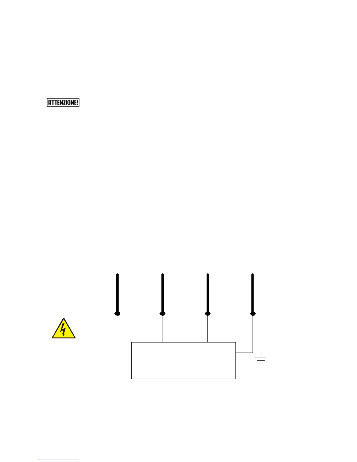
Control of any 3-way valve for the DHW circuit
The fireplace heating system control unit (supplied on request
with he fireplace heating system) is equipped with a control as
per standard for any motorised 3-way valve to be installed on the
domestic hot water circuit. The control unit electric control board
has three clamps (VALVE) to be used to control this 3-way valve.
The three clamps on the electric control board have the following
function:
N = COMMON TO 3-WAY VALVE
L ON = FIREPLACE HEATING SYSTEM SIDE
L OFF = GAS BOILER SIDE
Below find a connection example using a 3-way valve with spring
return. Remember that the hydraulic connection must be made in a
way that when the valve is at rest, the water passes from the gas
boiler. Only when the fireplace heating system temperature is
sufficient (value set on the valve thermostat), the 3-way valve is
powered and therefore closes the gas boiler circuit and opens the
fireplace heating system circuit.
clamp L OFF
Earth
clamp N
clamp L ON
3-WAY VALVE
Page 28
28
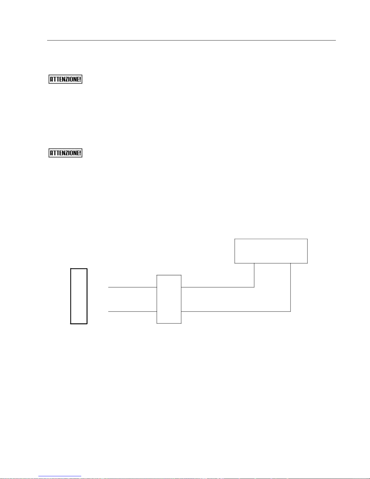
Control of any coupled boiler
If the fireplace heating system is to be coupled with another
boiler already installed in the system (e.g. wall-hung gas boiler), it
must be ensured that when the fireplace heating system
functions for the heating system, the boiler stops. So the fireplace
heating system intervenes on the coupled boiler when the
temperature set in the aux thermostat of the wood-burning
fireplace heating system control unit is reached. In this way,
there will never be two boilers functioning simultaneously in the
same system. The coupled boiler will always be able to be used
for the production of domestic hot water.
It is therefore easy to connect the clamps with the two wires
connected to a relay that will control the Room Thermostat inlet
of the coupled boiler.
RELAY
Boiler room
themrostat inlet
clamp N
clamp L ON
AUX OR PUMP
THERMOSTAT
Page 29
29
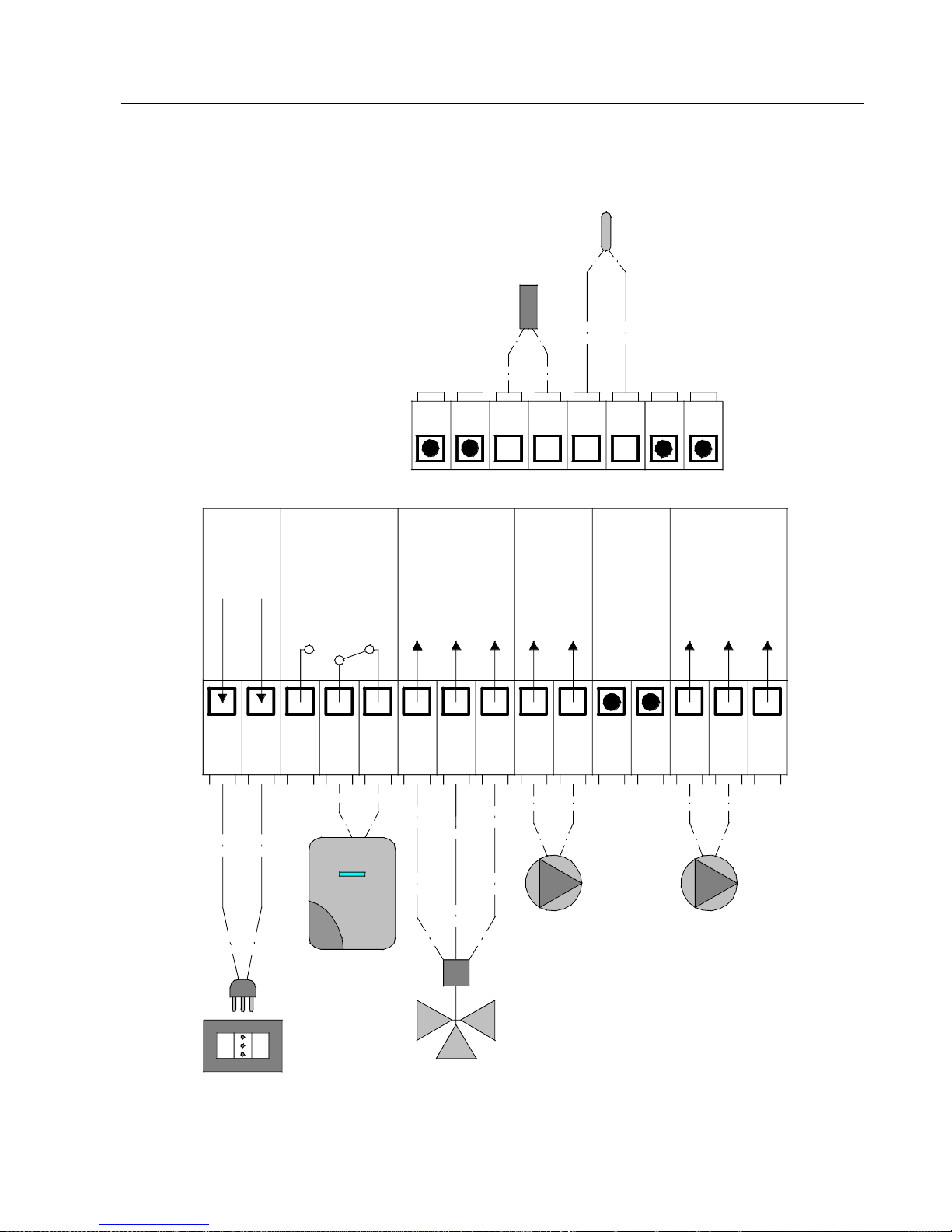
Example of electrical connection
LINEA
230 Vac
POMPA
230 Vac
VALVOLA
230 Vac
AUX
1
2
3
4
5
6
7
8
9
10 11
12 1314
N
L
LON
LON
LON
LOFF
NO
COM
NC
23
22 2120 1918
LIVEL.
SONDA
15
LOFF
HEATING SYSTEM
PUMP
CIRCULATION
KNOB
3-WAY
MOTORISED
VALVE
GAS BOILER
ROOM
THERMOSTAT
CONTACT
WATER
LEVEL
SENSOR
17 16
N
N
N
SERV
230 Vac
WATER
TEMPERATURE
PROBE
ELECTRICAL
POWER
SUPPLY
Page 30

30
LINEA: Connect the 1 and 2 clamps to the electrical power supply.
AUX: This is used to control a boiler associated with the heating system.
Therefore connect the 4 and 5 clamps (or 3 and 4 depending on the type of
connection to the associated boiler) to the TA (Room Thermostat) contact of
the boiler. It is then possible to check the boiler associated with the
temperature on the AUX thermostat; above the set temperature the
associated boiler turns off and on again only below the set temperature
VALVOLA: Connect the 6, 7 and 8 clamps to the 3-way motorised valve.
It is used to control a motorized 3-way valve (or two 2-way motorised
valves) installed in the dhw system. The valve opens the circuit with
temperatures higher than those set on the VALVE thermostat (230V
voltage on clamps 6 and 7) and close the circuit with lower temperatures
(230V voltage on clamps 7 and 8).
SERV: Connect clamps 9 and 10 to the circulation pump. This is used to
control the circulation pump installed on the fireplace heating system. The
circulation pump will operate at temperatures higher than those set on the
SERV thermostat. We recommend setting temperatures ranging between
35°C and 40°C for the SERV thermostat to optimize the yield for the water
and prevent condensation, which would damage the body of the fireplace
heating system, from forming.
POMPA: Connect the clamps 13 and 14 to the pump of the heating system.
This is used to control the pump installed on the heating system. The
heating pump will operate at temperatures higher than those set on the
PUMP thermostat. We recommend setting the pump thermostat at
temperatures greater the 55°C to prevent condensation, which would
damage the body of the fireplace heating system, from forming.
SONDA: Connect the water temperature probe to clamps 18 and 19. This is
used to detect the water temperature inside the fireplace heating system. if
the probe is not connected, the control unit's display shows “Lo”; if the
probe is in short-circuit, the display shows “Hi”.
LIVELLOSTATO: Connect the level switch (water level sensor) to clamps
20 and 21. This is used to report the water level inside the body of fireplace
heating system has not been reached.
Page 31
31
Hydraulic connection
The hydraulic connections must be made in a rational mode. The
fireplace heating system can be coupled to any other boiler already
installed in the system; naturally it is indispensable to insert the due
safety devices and shut-offs according to the system used.
N.B.: THE SYSTEM MUST BE DIMENSIONED WITH AVERAGE
FLOW TEMPERATURE OF 55°C.
IF THE FIREPLACE HEATING SYSTEM IS INSTALLED AS
THE ONLY SOURCE OF HEATING, IN ALL CASES IT IS
DEEMED NECESSARY THAT THE SYSTEM IS SUPPLIED
WITH: CLOSED EXPANSION VESSEL, FILLING UNIT,
SYSTEM SAFETY VALVE (2.5 BAR), DHW SAFETY VALVE (6
BAR).
THE FIREPLACE HEATING SYSTEM MUST BE INSTALLED
EXCLUSIVELY BY QUALIFIED STAFF. SCRUPULOUSLY
COMPLY WITH THAT STATED IN THIS GUIDE;
ALL LIABILITY IS DECLINED FOR DAMAGE CAUSED BY
INCORRECT ASSEMBLY.
REMEMBER TO INSERT THE CONTROL UNIT PROBES AND
BULBS INTO THE APPROPRIATE HOUSINGS.
DO NOT PASS ELECTRIC CABLES IN THE IMMEDIATE
VICINITY OF THE FLUE GAS PIPE, UNLESS THEY ARE
INSULATED WITH SUITABLE MATERIALS.
IN THE CASE OF WATER WITH FIXED RESIDUE AT 180°C
THAT EXCEEDS 300 MG/L IT IS INDISPENSABLE TO
INSTALL A WATER SOFTENER UPSTREAM FROM THE
FIREPLACE HEATING SYSTEM INLET.
Page 32
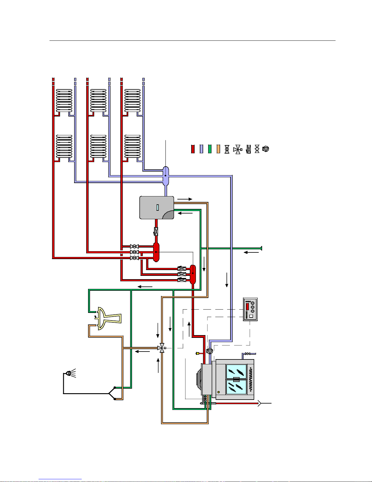
32
Example of fireplace heating system-boiler connection
DOMESTIC COLD
WATER INLET
BOILING
DISCHARGE
RETURN
MANIFOLD
FLOW
MANIFOLDS
DOMESTIC HOT
WATER OUTLET
GAS BOILER
Key:
SYSTEM FLOW
SYSTEM RETURN
DOMESTIC COLD WATER
DOMESTIC HOT WA TER
ZONE VAL VE
MOTORISED THREE-WAY
VA LVE
NON-RETURN VA
LVE
BA LL VA LVE
CIRCULAT ION PUMP
ZONE
1
ZONE
2
ZONE
3
FIREPLACE L OAD VIA
FLOAT
FIREPLACE
DRAIN
CONTROL
UNIT
S.R.L. S.R.L.
VENT VALVE
THE FOLLOWING MUST BE INSTALLED ON THE HYDRAULIC HEATING PLANT: LOADING UNIT, CLOSED EXPANSION VESSEL SUITABLE
FOR THE PLANT AND RELEVANT SAFETY VALVES. THE DHW SYSTEM MUST HAVE A SAFETY VALVE CALIBRATED AT 6 BAR. (If it is deemed appropriate, the above
-mentioned components present in the wall
-hung boiler can be made use of).
This layout is purely indicative and does not bind or make KLOVER s.r.l. and its collaborators liable. The plan and consequen
t set-up must
be realised in compliance with the Standards in force.
Page 33
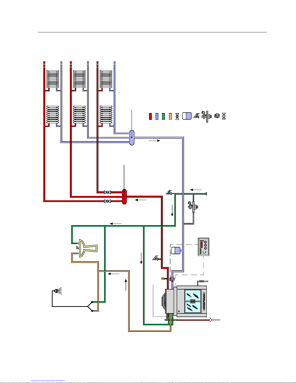
33
Example of fireplace heating system connection only
DOMESTIC COLD
WATER
RETURN
MANIFOLD
DOMESTIC HO
WATER OUTLET
Key:
SYSTEM FLOW
SYSTEM RETURN
DOMESTIC COLD WATER
DOMESTIC HOT WATER
ZONE VAL VE
CLOSED EXPANSION VESSELSAFETY VALVE
FILLING UNIT
CIRCULATION PUMP
BALL VA LVE
ZONE
1
ZONE
2
ZONE
3
FLOW
MANIFOLD
2,5 BAR
6 BAR
FIREPLACE
DRAIN
FIREPLACE LOAD VIA
FLOAT
S.R.L.
BOILING
DISCHARGE
S.R.L. S.R.L.
VENT VALVE
CONTROL
UNIT
This layout is purely indicative and does not bind or make KLOVER s.r.l. and its collaborators liable. The plan and consequen
t set-up must
be realised in compliance with the Standards in force.
Page 34

34
FIREPLACE HEATING SYSTEM COVERING
When installation has been completed, do not cover the
fireplace heating system for at least 6-7 days, in order to
verify the tightness of all hydraulic joints of the fireplace
heating system itself.
BEFORE COVERING THE FIREPLACE HEATING SYSTEM,
DISASSEMBLE THE TWO DOOR LOCK ANGLES AND
CHECK THAT THE STEEL CABLE IS INSIDE THE METAL
WHEEL GROOVE.
All of the front part must be on view and able to be
inspected. The two angles for inspection of the wheel and
steel rope must be easily accessible also after the fireplace
heating system has been covered.
If the fireplace heating system should have defects or
breakage, the warranty excludes all hydraulic
disassembly and re-assembly works, any masonry work
and any other intervention that is made necessary in
order to remove the fireplace heating system from the
covering.
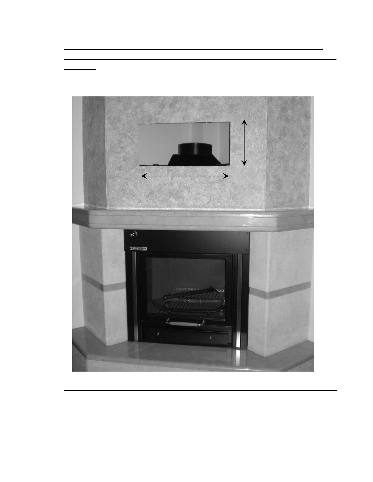
The plasterboard hood must be easy to inspect and/or
disassemble. An inspection hole must be made (see following
figure) in order to access the upper part of the fireplace heating
system.
Page 35
35
An example of covering is given below, indicating the minimum
measurements to leave for any inspections of the fireplace heating
system:
The inspection hole can be covered with a bracket or aeration grid.
60 cm minimum
30 cm minimum
Page 36

36
COMMISSIONING
Filling the system for the first time
After having connected the fireplace heating system, fill the system as
follows:
Loosen the caps of any air vent valves;
If necessary, very slowly loosen the pump/s vent valve cap,
making the fluid flow for a few seconds;
Have the system filled very slowly in order to allow air
bubbles to escape from the system through the air bleeding
valve;
Bleed all radiators and any other deaeration systems
present in the system in order to ensure that there are no
air bubbles;
When installation has been completed, do not cover the
fireplace heating system for at least 6-7 days, in order to
verify the tightness of all hydraulic joints and of the
fireplace heating system itself.
BEFORE COVERING THE FIREPLACE HEATING SYSTEM,
DISASSEMBLE THE TWO DOOR LOCK ANGLES AND
CHECK THAT THE STEEL CABLE IS INSIDE THE METAL
WHEEL GROOVE.
All of the front part must be on view and able to be
inspected. The two angles for inspection of the wheel and
steel rope must be easily accessible.
Page 37

37
Filling the fireplace heating system
When the system has been filled, then fill the fireplace heating
system via the float. It is recommended to install a ball valve in
the fireplace loading pipe in order to isolate the float if the same
should break. Regulate this ball valve in a way that the
pressure of the float cock is not particularly high (LESS
THAN 1 BAR).
Regulate the float dipstick in a way that the exchangers are
completely inside the fireplace heating system water.
THE BEST LEVEL IS REACHED WHEN THE WATER
EXCEEDS THE COPPER HEAT EXCHANGERS BY A FEW
CENTIMETRES.
N.B.: IF THE FIREPLACE HEATING SYSTEM IS INSTALLED AS
THE ONLY SOURCE OF HEATING, IN ALL CASES IT IS
DEEMED NECESSARY THAT THE SYSTEM IS SUPPLIED
WITH: CLOSED EXPANSION VESSEL, FILLING UNIT,
SYSTEM SAFETY VALVE (2.5 BAR), DHW SAFETY VALVE (6
BAR).
Never empty the water inside the fireplace heating system
so as not to compromise the duration of the same.
Page 38

38
Ignition
Perform the following operations:
Before switching the fireplace heating system on, make
sure that the control unit switch is on;
Make sure that there is water in the system;
Regulate the thermostat that controls the pump to a
temperature of 55-60 °C;
Open the smoke damper completely (optional);
Open the primary air front slots;
Open the hatches or lift the vertical sliding door;
Light the fire using seasoned, thin wood, if possible;
When the wood has ignited well, close the doors, adjust the
smoke damper and the combustion agent air via the front
slots;
NEVER IGNITE THE FIREPLACE HEATING SYSTEM USING
ALCOHOL OR OTHER HIGHLY INFLAMMABLE LIQUIDS.
Remember always to open the smoke damper and close the
primary air front slots a few seconds before loading the
fireplace heating system with new wood in order to prevent
the backflow of smoke into the environment.
Page 39

39
Boiling
If for any reason (power cut, a pump fault, too much wood, etc…), the
water in the fireplace body reaches boiling point, carry out the
following operations immediately, IN SPITE THAT THE FIREPLACE
HEATING SYSTEM GUARANTEES ABSOLUTE SAFETY:
Open the fireplace heating system smoke damper;
Open the DHW cock and leave the water to run until the
temperature in the fireplace body drops (only for models
connected to the DHW plant);
Open the hatches or the vertical sliding door;
Close the primary air front slots completely
After having ascertained the reason for the high temperature, wait
for every thing to go back to normal (temperature below 60°C)
check on the control unit that the water level LED is not on and, if
necessary, open the cold water load from the float.
Anti-freeze protection
In intensely cold periods it is good practice that the heating system
remains running. In the case of prolonged absence, anti-freeze must
be added to the heating water or the system must be completely
emptied.
In a system subject to being emptied frequently it is indispensable that
filling is performed with water that has been appropriately treated to
eliminate hardness that can lead to lime scale deposits.
Functioning principle
The fireplace heating system is just a wood-burning boiler made in a
way to be able to be inserted into a traditional fireplace.
You therefore have the pleasure of seeing the flame through the
ceramic glass like in a normal fireplace, but the radiators in the home
are also heated and DHW is supplied for all of the family.
The fireplace heating system can be integrated into an appliance that
is already installed (gas boiler, diesel oil boiler or wood-burning etc...)
or can function as a unique source of heating for the home.
Page 40
40
MAINTENANCE
Cleaning the body-boiler
Punctual and systematic maintenance is a fundamental
component for perfect functioning, excellent heat yield and
duration of the appliance through time. It is therefore
recommended to clean the boiler body periodically (at least once
a year).
Before performing any cleaning or maintenance, make sure
that the fireplace heating system is off and completely cold
and that the ash is also cold.
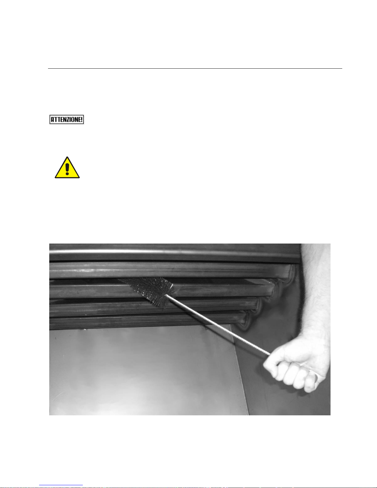
The special manufacturing design means it is easier to access
the elements. To clean the elements just open the large door
and access all parts affected by flue gas.
It is possible to reach all points affected by the flue gas by acting
as follows:
Use the brush supplied to clean the 4 slanted elements of the flue gas pass
inside the combustion chamber.
Page 41
41
Any deposits on the walls of the combustion chamber (if
particularly resinous wood is burned) can be eliminated by
making the fireplace heating system work at maximum conditions
for 30-40 minutes (in this case take the thermostat to 85°C) by
burning dry wood or, even better, charcoal.
Leave the fire to go out and then scrape the inside walls using a
steel spatula.
We recommend you periodically remove ash from the base of the
combustion chamber in order to always ensure a efficient flow of
combustion agent air.
Cleaning the ceramic glass
Only clean the ceramic glass when the fireplace heating unit is
off and completely cold. Use a damp cloth and specific detergent
for ceramic glasses. Do not use abrasive sponges. To clean the
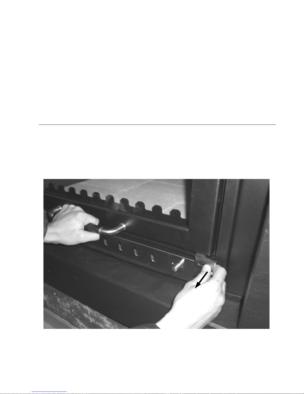
glass is essential to open the door fitted with a "hinge opening".
To open the hinged door you should release the designated hook as shown
in the photo. The vertical sliding door must be open.
Page 42
42
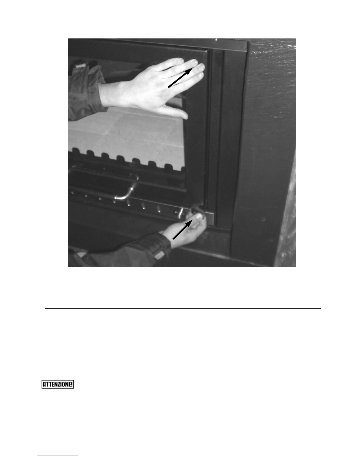
To close the hinged door, you should push both at the top and at the
bottom - as shown in the photo - making sure that both parts are fixed
correctly when they are fastened.
Cleaning the flue
The flue must be cleaned at least once a year at the start of the
winter season, and also every time it is necessary.
If it is not cleaned, the functioning of the fireplace heating system and
its components may be jeopardised.
The frequency of cleaning of the fireplace heating system
and the flue depend on the quality of the wood used.
USE TOP QUALITY WOOD IN ORDER TO OBTAIN THE BEST
RESULTS.
Page 43
43
Maintenance of the boiler body
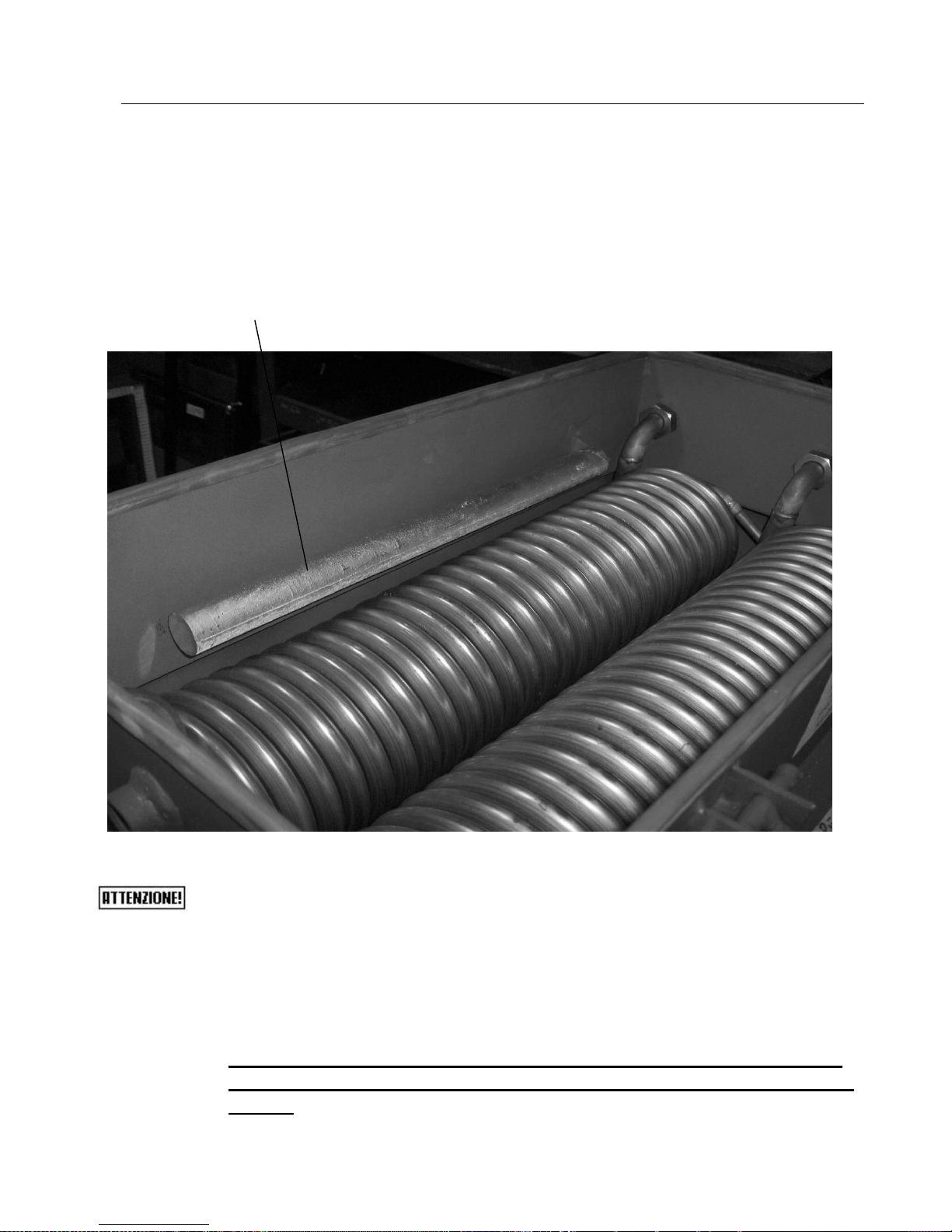
The fireplace heating system is equipped with a special magnesium
anode to protect the boiler body and stainless steel heat exchangers
from corrosion due to stray currents in the system.
This anode protects from galvanic corrosion.
The anode must be controlled at least once a year and
replaced when its diameter measures less than 15 mm.
To inspect the boiler body, remove the upper lid fixed using
the four knobs.
To replace the anode, just loosen it and screw-in the
new one, paying attention that the latter does not come
into contact with the stainless steel heat exchangers.
NEVER EMPTY THE WATER INSIDE THE FIREPLACE HEATING
SYSTEM SO AS NOT TO COMPROMISE THE DURATION OF THE
SAME.
MAGNESIUM ANODE
Page 44

44
THE WOOD TO BURN
Wood features
Wood is one of the most precious materials offered by nature.
For heating purposes, it must be verified that the features
of the wood satisfy some important requisites that must not be
ignored, the most important of which is without a doubt the correct
seasoning or drying, in other words the wood must have the correct
amount of humidity, around 10-15%, therefore also the
period of the year in which it is felled becomes important. This should
coincide with the winter period. The correct seasoning (at least 2
years) allows to have a fuel with excellent yield and not very pollutant.
It must be kept in covered, well-aired places, already cut appropriately
into pieces suitable for the hearth of the fireplace heating system.
The wood is divided into softwood and hardwood on the basis of the
weight kg of a cubed metre of material. A softwood that weighs about
300- 350 kg/m3 is fir, pine, poplar, European alder, chestnut, willow,
while hardwood that weighs about 350-400 kg/m3 is beech,
ash, carpine, acacia and oak.
Softwood ignites easily, is consumed quickly and
develops a long flame and is used in ovens that require a
long flame pass. Hardwood is more compact, the
combustion is slower with short flame, it lasts longer and is more
suitable for domestic central heating.
The wood to be burned for heating purposes has
different features according to the plant variety from which it is
obtained. Not all woods are the same and the features regarding the
drying time and the calorific value vary from plant to plant.
The calorific value depends on the level of humidity and its density.
Top quality woods are beech, ash carpine and acacia.
Avoid resinous woods as they could
compromise the duration of the fireplace heating system.
In fact, resinous woods have a rather sooty combustion and
therefore, the flue and fireplace heating system must be cleaned more
often.
Page 45

45
The calorific value of the different types of wood depends greatly on
their humidity and consequently the power of the fireplace heating
system is directly affected by the type of wood used, on average a
well-seasoned wood has a calorific value of 3200 kcal/kg.
Calorific value of wood depending on its humidity:
CALORIFIC VALUE of the wood means the amount of heat yielded
during combustion, referring to the unit quantity of the material burned.
The calorific value of a wood species depends on the presence of
lignin (6000 Kcal/Kg) or cellulose (4000 Kcal/Kg) as well as the
abundance of resin (8500 Kcal/Kg).
The calorific value relative to the unit of weight ( = absolute) id highest
in Conifers
Conifers absolute calorific value: 4700 Kcal/Kg
Broad-leaved species absolute calorific value: 4350
Kcal/Kg.
In opposition the SPECIFIC WEIGHT of the “broad-leaved species” is
greater; therefore equal volumes introduced into the fireplace heating
system, both the weight and amount of heat available for combustion
are greater; in practice the relative calorific value is higher (referring to
a unit of volume).
Example: the calorific value of the white fir is practically the same as
that of the oak, but the oak has a specific weight that is double that of
the fir. Therefore half the volume of oak must be introduced into the
fireplace heating system in order to have the same "heat" obtained
with the fir.
% of
humidity
Calorific value
kcal/kg
15%
3490
20%
3250
25%
3010
30%
2780
35%
2450
40%
2300
Page 46

46
*Calorific value
(Kcal/Kg)
**Specific weight
(Kg/m3)
WHITE FIR
4650
440
RED FIR
4857
450
MAPLE
4607
740
BIRCH
4968
650
CARPINO NERO
4640
820
CHESTNUT
4599
580
OAK
4648
900
CYPRESS
5920
620
BEECH
4617
750
ASH
5350
720
HOLM OAK
/
960
LARCH
4050
660
EUROPEAN ALDER
4700
530
MANNA ASH
/
760
PLATAN / 690
CYPRESS POPLAR
4130
500
ROBINIA
4500
790
DOWNY OAK
4631
880
* theoretical absolute superior
** wood seasoned in the air; residual humidity 12-15 %
Page 47

47
TROUBLESHOOTING
INSUFFICIENT DRAUGHT.
DIFFICULT FLUE GAS EVACUATION.
DISTRIBUTION OF THE FLUE GAS IN THE INDOOR ENVIRONMENT.
ELEMENTS TO CHECK
ORIGIN
External air vent
Inexistent;
Gate valve closed;
Accidental obstruction;
Insufficient section.
Air vent (pipe)
Insufficient section.
Flow regulator
Closed or badly regulated
Hood gate valve
Closed or badly regulated.
Wood
Excessive humidity.
Flue
Hood fitting/flue gas channel
Insufficient section;
Insufficient height;
Accidental obstructions;
Periodical cleaning not performed;
Heat insulation or insulation insufficient or
inexistent;
Use of unsuitable materials;
Heat insulation or insulation absent or insufficient;
Inadequate section (square or rectangular) in
incorrect dimensioning;
Narrowing or presence of obstacles to the flow of
flue gas;
Accidental obstructions;
Infiltrations of parasite air due to the use of
materials non-impermeable to gas and liquids;
Insufficient height.
Chimney
The outlet height in reflow zone;
Vicinity or approach to other chimneys;
Vicinity of obstacles, both natural and artificial;
Obstruction ( Example: birds nests);
Inadequate chimney pot shape;
Insufficient emission section.
Page 48
48
CONDENSATE ESCAPING THROUGH THE MASONRY.
ELEMENTS TO CHECK
ORIGIN
Flue gas channel
Flue
Condensate tray
Use of inadequate material;
Absence or installation not performed state-of-the-
art of the relevant condensate collector with drain
and connected to the disposal system.
SELF-COMBUSTION INSIDE THE FLUE.
ELEMENTS TO CHECK
ORIGIN
Hood fitting/flue gas channel
Flue gas channel
Flue
Periodical cleaning not performed.
WATER INSIDE THE FIREPLACE HEATING SYSTEM.
ELEMENTS TO CHECK
ORIGIN
Flue
Chimney
In total or partial absence of the chimney, the flue
is not realised with start parallel to the appliance.
Inadequate chimney.
Pump thermostat
Pump start-up at temperatures that are too low
(condensate is created).
To prevent flue gas from escaping at the time of loading the wood,
close the primary air front slots completely and fully open the smoke
damper.
Page 49

49
USEFUL ADVICE
1. The temperature of the thermostat that controls the pump must never
be set below 55 °C.
2. The fireplace heating system must have a pump and the warranty
becomes null and void if it is mounted without connecting the control
unit thermostat (use KLOVER control units).
3. When priority is to be given to DHW (for prepared models only), take
the pump thermostat to 75°C (or set the DHW function) and burn small
pieces of dry wood in order to increase the flame. After use of the
DHW, lower the thermostat to 55-60 °C.
4. Open the smoke damper before loading the wood.
5. Never empty the content of the water from the fireplace heater
system, so as not to compromise the duration of the same.
ALL LIABILITY IS DECLINED REGARDING PROBLEMS DERIVING
FROM THE FAILURE TO APPLY THE STANDARDS CONTAINED IN
THIS MANUAL.
Page 50

50
WARRANTY
CERTIFICATE
KLOVER s.r.l. guarantees the quality of materials, good
construction and functionality of the fireplace heating system
for the duration of 5 years, under the following conditions:
The fireplace heating system which, on its unquestionable judgement,
has material or construction faults will be repaired or replaced; with
exclusion of all cost for interventions at domicile, transport, reset
(hydraulic disassembly, assembly operations, any masonry and any other
intervention necessary) and accessory materials;
The warranty excludes the ceramic glass, ceramic-majolica coverings
and refractory bricks, because as they are very fragile to blows, they can
be damaged even accidentally, all the gaskets, the control board, all
electric components and every thing that is not part of the boiler and not
produced by ourselves;
Incorrect installation carried out by unqualified staff, tampering,
failure to comply with the Standards contained in this guide and those
regarding “state-of-the-art installation”, make all warranty rights become
null and void; the same for damage deriving from external factors.
Direct or indirect “reimbursement” is excluded in all cases whatever
the nature or cause; For the appliances that require an intervention at
domicile, the user must pay “a contribution for transfer expenses” in
force at the date of the intervention. Within the first month of the
warranty the repairs at domicile will be performed free of charge, except
for interventions not covered by the warranty as previously specified,
which are the total responsibility of the user;
Remember that the goods are transported under the customer’s
responsibility, even if delivered free to destination, therefore we are
exonerated from any responsibility for damage caused by loading and
unloading, accidental blows, storage in unsuitable places etc;
The warranty must only be considered valid if the attached card is
returned within 10 days from the date of purchase fully filled-in;
The competent Law Court for any disputes is Verona.
Page 51

51
Page 52

52
WOOD BURNING FIREPLACE HEATING SYSTEMS and THERMO COOKERS
WOOD and PELLET BURNING THERMO STOVES
WOOD BURNING BOILERS
Via A. Volta, 8 – 37047 San Bonifacio (VR) Italy
Tel. 0039 045 6101859 – Fax 0039 045 6101858
S.R.L.
 Loading...