

Page 1

Pellet-fired central heating
cooker
SMART 120
INSTALLATION,
USE AND MAINTENANCE
USEFUL TIPS
User guide
EN
Page 2

2
Page 3

Dear customer,
First of all we would to thank you for choosing a “KLOVER” product, and we hope you are completely
satisfied with your purchase.
We recommend that you read the warranty certificate carefully, which you will find on the last page of this
User Guide; call the Authorised Technical Assistance Centre (TAC) immediately for commissioning and
validating your warranty.
We would like to thank you again for trusting KLOVER products, and we also inform you that these
models are the result of forty years experience in the manufacture of solid fuel products using water as
heat transfer fluid.
Each and every single part of our central heating cookers is manufactured by qualified staff using the most
modern work equipment.
The manual contains a detailed description of the central heating cooker and its operation along with
instructions for proper installation, basic maintenance and checks to be run regularly. It also contains
practical advice to achieve maximum efficiency with minimum fuel consumption.
The cooker heat output can vary depending on the type of pellet used.
Enjoy heat with KLOVER!
Smoke Control Areas
Under the Clean Air Act local authorities may declare the whole or part of the district of the authority to be a smoke
control area. It is an offence to emit smoke from a chimney of a building, from a furnace or from any fixed boiler if located
in a designated smoke control area. It is also an offence to acquire an "unauthorised fuel" for use within a smoke control
area unless it is used in an "exempt" appliance ("exempted" from the controls which generally apply in the smoke control
area).
The Secretary of State for Environment, Food and Rural Affairs has powers under the Act to authorise smokeless fuels
or exempt appliances for use in smoke control areas in England. In Scotland and Wales this power rests with Ministers in
the devolved administrations for those countries. Separate legislation, the Clean Air (Northern Ireland) Order 1981,
applies in Northern Ireland. Therefore it is a requirement that fuels burnt or obtained for use in smoke control areas have
been "authorised" in Regulations and that appliances used to burn solid fuel in those areas (other than "authorised"
fuels) have been exempted by an Order made and signed by the Secretary of State or Minister in the devolved
administrations.
Further information on the requirements of the Clean Air Act can be found here :
http://smokecontrol.defra.gov.uk/
Your local authority is responsible for implementing the Clean Air Act 1993 including designation and supervision of
smoke control areas and you can contact them for details of Clean Air Act requirements”
“The Klover SMART 120 (models - SM120, SM120-BP, SM120-P, SM120-B) have been recommended as suitable
for use in smoke control areas when burning wood pellets.”
Page 4

4
Technical Support
Klover pellet stoves are imported and distributed by FirePower Heating, Unit 11/12
Quadrant Distribution Center, Quedgeley, Gloucester, GL2 2RN.
UK technical and product support is provided by FirePower Heating who can be reached
on 0844 3320156.
Certificate number NQA B 0002/29 - NQA B 0002/30 - NQA B 0002/31 - NQA B 0002/32
Copyright
All rights reserved. The reproduction of any part of this manual, in any form, without the explicit written
permission of KLOVER Srl. is forbidden. The content of this manual can be modified without forewarning.
Although we have carefully collected and verified the documentation contained in this manual, KLOVER srl
cannot be held liable for how you utilise it.
Copyright © 2012 KLOVER srl
Latest revision: 1.0 – May 2014
Page 5

5
DICHIARAZIONE DI
CONFORMITÀ
DECLARATION OF
CONFORMITY
In accordo con la Direttiva 89/106/CEE (Prodotti da Costruzione), il Regolamento CE n. 1935/2004 (Materiali e Oggetti destinati
a venire a contatto con prodotti alimentari), la Direttiva 2006/95/CEE (Bassa Tensione) e la Direttiva 2004/108/CEE
(Compatibilità Elettromagnetica).
According to the Directive 89/106/EEC (Construction Products), the EC Regulation No. 1935/2004 (Materials and Articles
intended to come into contact with foodstuffs), the Directive 2006/95/EEC (Low Voltage) and the Directive 89/336/EEC
(Electromagnetic Compatibility).
N° di identificazione - Identification No.
:
SM120-01
Emesso da - Issued by
:
KLOVER s.r.l.
Via A. Volta, 8
37047 San Bonifacio (VR)
Tipo di apparecchio - Type of equipment
: Wooden pellet burning appliance for domestic
heating and cooking with the possibility of
producing domestic hot water.
Marchio commerciale -Trademark
:
KLOVER
Modello o tipo - Model or type
:
SMART 120
Uso – Use
:
Domestic heating and cooking with possibility
of producing domestic hot water
Costruttore – Manufacturer
:
KLOVER s.r.l.
Via A. Volta, 8
37047 San Bonifacio (VR)
Ente – Laboratory
:
NB 1880
ACTECO S.R.L.
I – 33084 Cordenons (PN)
Via Amman, 41
Le norme armonizzate o le specifiche tecniche (designazioni) che sono state applicate in accordo con le regole della buona arte
in materia di sicurezza in vigore nella CEE sono:
The following harmonised standards or technical specifications (designations) which comply with good engineering practice in
safety matters in force within the EEC have been applied:
Norme o altri riferimenti normative
Standards or other normative documents
Rapporto di Prova ITT
Initial Type Tests Report
EN 12815
0140-21NB
EN 14785
EN 60335-1
EN 50165
EN 55014-1
EN 61000-3-2
EN 61000-3-3
EN 55014-2
In qualità di costruttore e/o rappresentante autorizzato della società all’interno della CEE, si dichiara sotto la propria
responsabilità che gli apparecchi sono conformi alle esigenze essenziali previste dalle Direttive su menzionate.
As the manufacturer’s authorised representative established within EEC, we declare under out sole responsibility that the
equipment follows the provisions of the Directives stated above.
San Bonifacio (VR), 01/03/12
Mario Muraro
Chairman of the Board
Page 6

6
TABLE OF CONTENTS
Introduction……………………………………………………………………………………………… 6
Important safety instructions………………………………………………………………..................... 6
Some precautions………………………………………………………………………………............... 6
Conventions used in the manual………………………………………………………………………… 6
Destination of use…………………………………………………………………………………………. 7
Installation regulations……………………………………………………………………………………. 7
Health and safety………………………………………………………………………………………….. 7
The machine and the pellets…………………………………………………………………………. 8
Central heating cooker components…………………………………………………………………….. 8
Connections data sheet (Model with upper flue gas outlet)…………………………………………... 12
Connections data sheet (Model with rear flue gas outlet)…………………………………………….. 13
Technical features……………….………………………………………………………………………… 14
Pellet features……………………………………………………………………………………………… 15
Requisites of the place of installation………..…………………………………………………….. 16
Positioning………………………………………………………………………………………………….. 16
Spaces around and above the central heating cooker.……………………………………………….. 16
External air vent…………………………………………………………………………………………… 17
Flue and connection to the same – Chimney…………………………………………………………... 17
Electric connection……………………………………………………………………………………. 21
Control of any coupled boiler…………………………………………………………………………….. 21
Control of a three-way motorised valve for the DHW system….................................................... 21
Connection to room thermostat….………………………………………………………………………. 22
Pipe connection………………………………………………………………………………………... 23
Connection examples…………………………………………………………………………………….. 24
Cleaning and Maintenance…………………………………………………………………………… 25
Precautions before cleaning……………………………………………………………………………… 25
Routine cleaning…………………………………………………………………………………………… 25
Extraordinary cleaning……………………………………………………………………………………. 27
Yearly cleaning…………………………………………………………………………………………….. 34
Cleaning the ceramic glass………………………………………………………………………………. 39
Cleaning the flue…………………………………………………………………………………………... 39
Maintenance………………………………………………………………………………………………. 39
The display………………………………………………………………………………………………. 40
The menu………………………………………………………………………………………………… 43
Commissioning………………………………………………………………………………………… 47
Filling the system for the first time……………………………………………………………………….. 47
Pellet loading and connection to the mains…………………………………………………………….. 47
Central heating cooker ignition cycle……….…………………………………………………………… 47
Central heating cooker working mode…………………………………………………………………... 48
Producing domestic hot water (prepared models only)……………………………………………….. 49
Cooking plate/oven output………………………………………………………………………………... 49
Central heating cooker switch-off………………………………………………………………………... 50
Modification of DHW, room and water temperature setting…………………………………………... 51
Alarms signal………………………………………………………………………………………………. 52
It must be known…………………………………………………………………………………………... 52
What happens if….…………………………………………………………………………………….. 53
Circuit board parameters……………………………………………………………………………... 54
Wiring diagram……..…………………………………………………………………………………… 56
Notes……………………………………………………………………………………………………… 57
Warranty…………………………………………………………………………………………………. 58
Page 7

7
INTRODUCTION
Important safety instructions
Read these instructions before installing and using the product.
The central heating cooker installation and commissioning must be performed by skilled
personnel aware of the importance of respecting the Safety Standards in force. They will be
responsible for the definitive installation of the machinery and its consequent proper
operation.
KLOVER srl will not be held responsible if these precautions are not respected.
During installation of the appliance all local regulations, included those referring to National
and European Standards, must be followed.
Connect the product flue gas outlet to a flue that has the features given in the Connections section
in this user guide.
The appliance is not suitable for the installation on a shared flue system.
If the flue should catch fire, you must be provided with appropriate systems for damping down the
fire or call the fire service.
Connect the product to sockets with earth. Avoid using sockets controlled by switches or automatic
timers.
Do not use a damaged or worn power supply cable.
If a multiple socket is used, make sure that the total voltage of the connected devices does not
exceed that supported by the socket. Furthermore make sure that the total voltage of all these
devices connected to the socket does not exceed the maximum level accepted.
Do not use flammable substances to clean the appliance and its elements.
Do not leave flammable containers and substances in the room where the central heating cooker is
installed.
Do not use the appliance as incinerator or in any other way different from that for which it has been
designed.
Do not use fuels different to those which are recommended.
Do not use liquid fuels.
External surfaces of the appliance reach high temperatures when it is running; operate with caution
in order to avoid burns.
Only use original spare parts recommended by the manufacturer.
Do not perform any unauthorised modification to the appliance.
The use of poor pellet or any other material can damage the central heating cooker features,
leading to the termination of the warranty and exempting the manufacturer from all
responsibility.
The Klover pellet products are not suitable for use in smokeless zones.
Some Precautions
Do not touch the hot components of the product (ceramic glass, flue pipe) during normal operation.
Use the appropriate button to switch the electrical panel off. Do not disconnect the power supply
cable while the central heating cooker is running.
Keep children away from the central heating cooker when it is running since they could get burnt by
touching its hot components.
Children and inexperienced people are not allowed to use the appliance.
NEVER open the door of the central heating cooker while it is running.
Conventions used in the manual
Danger to the central heating cooker features.
General danger to personal safety.
Danger to people and objects due to materials at high temperatures.
Danger to people and objects due to electric power.
Page 8

8
Burns hazard for people due to pressurised hot liquids.
(with temperature not exceeding boiling point at atmospheric pressure).
Destination of use
The new automatic operation SMART 120 central heating cooker by KLOVER has been designed
for heating your home.
The central heating cooker works exclusively with wood pellets and only with the hearth door
shut. Never open the door when the appliance is running.
The central heating cooker has a DOUBLE COMBUSTION system that ensures an extraordinary
efficiency average and “clean” flue gas exhaust with an emission of CO in the atmosphere which is
among the lowest in Europe.
Do not use the central heating cooker in disagreement with the directions contained in this
user guide. The central heating cooker is an indoor product.
This user guide is integral part of the central heating cooker.
If the product is transferred the user must give this manual to the new purchaser.
KLOVER S.R.L. DECLINES ANY RESPONSIBILITY IN CASE OF ACCIDENTS DUE TO THE FAILURE
TO COMPLY WITH THE SPECIFICATIONS OF THIS MANUAL.
FURTHERMORE, KLOVER S.R.L. DECLINES ANY RESPONSIBILITY DUE TO INCORRECT USE OF
THE PRODUCT BY THE USER, MODIFICATION AND/OR UNAUTHORISED REPAIRS, USE OF NON ORIGINAL SPARE PARTS OR SIMPLY NOT SPECIFIC FOR THIS PRODUCT.
KLOVER S.R.L. IS NOT RESPONSIBLE FOR INSTALLATION OF THE THERMO STOVE. THE
INSTALLER IS THE ONLY PERSON RESPONSIBLE FOR THIS OPERATION AND HE IS ALSO
ENTRUSTED WITH CHECKING THE FLUE, THE EXTERNAL AIR VENT AND THE CORRECTNESS OF
THE SOLUTIONS SUGGESTED FOR INSTALLATION. ALL THE SAFETY STANDARDS CONTAINED IN
THE SPECIFIC LAW IN FORCE OF THE STATE WHERE THE THERMO STOVE IS INSTALLED MUST
BE RESPECTED.
ROUTINE MAINTENANCE MUST ONLY BE PERFORMED BY AUTHORISED AND QUALIFIED STAFF.
For the validity of the warranty, the user must comply with the directions contained in this
guide and in particular:
Use the central heating cooker according to its operational limits;
All maintenance must be performed constantly;
Only authorise experienced and competent people to use the central heating cooker.
Failure to comply with the requirements of this guide will void the warranty.
Installation Regulations
These operating and instructions cover the basic principles to ensure the correct installation of the pellet
stove, although particulars may need modification to reflect local site conditions. In all cases the installation
must comply with current Building Regulations, Local Authority By-laws and other regulations that affect the
installation of the stove.
The Building Regulations requirements can be met by adopting the relevant recommendations given in
British Standards BS 8303, BS 6461 and BS 7566 as
an alternative means to achieve an equivalent level of performance to that obtained by following the
guidance given in Approved Document J.
Health and Safety
Care must be taken when installing a Klover pellet stove to ensure that the requirements of the Health and
Safety at Work Act are met.
Handling
Adequate facilities must be available for loading, unloading and site handling the appliance bearing in mind
the weight of the appliance.
Page 9
9
THE MACHINE AND THE PELLETS
Central heating cooker components
The central heating cooker is delivered with the following equipment:
USE, INSTALLATION AND MAINTENANCE GUIDE;
1 POWER SUPPLY CABLE;
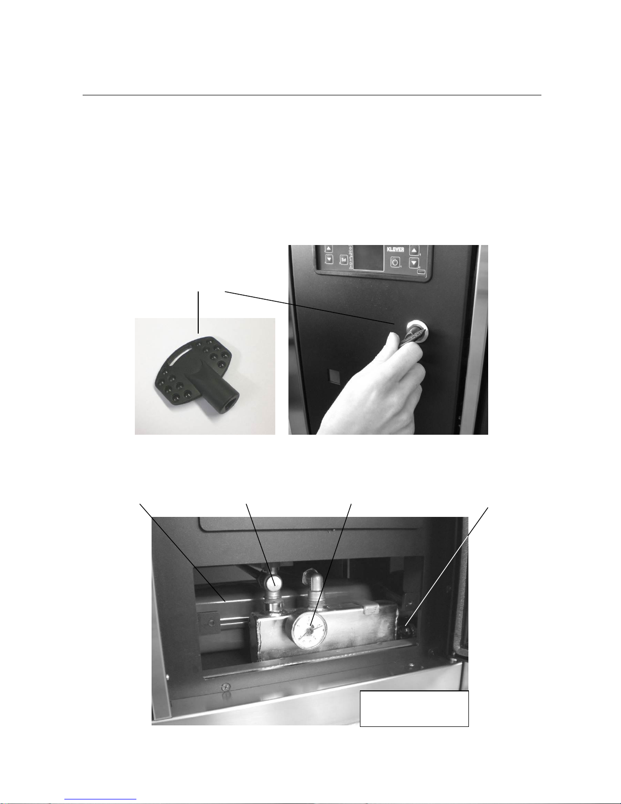
1 KEY FOR OPENING TECHNICAL COMPARTMENT;
2 BRUSHES FOR FLUE GAS TURN CLEANING (65 mm and 40 mm diameter).
This manual is an integral part of the machine. Should the central heating cooker be sold, the
manual must be provided to the new purchaser.
SYSTEM
PRESSURE
MANOMETER
BOILER BOILER
AND SYSTEM
LOAD COCK
BOILER BOILER
AND SYSTEM
DRAIN COCK
10 l EXPANSION
VESSEL
KEY FOR OPENING
TECHNICAL
COMPARTMENT
HYDRAULIC
COMPARTMENT
Page 10

10
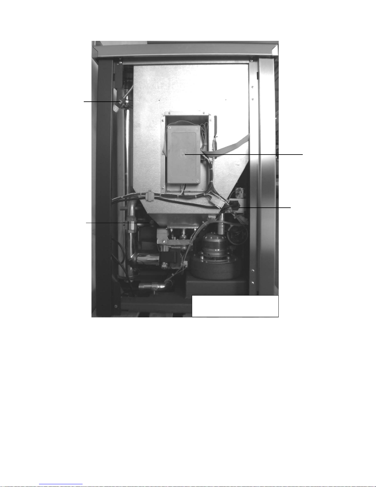
MAIN ON/OFF
SWITCH
SAFETY
THERMOSTAT
MANUAL RESET
SYSTEM PUMP
FLUE
PRESSURE
SWITCH
FLUE GAS
INTAKE
DEVICE
TECHNICAL
COMPARTMENT
Page 11
11
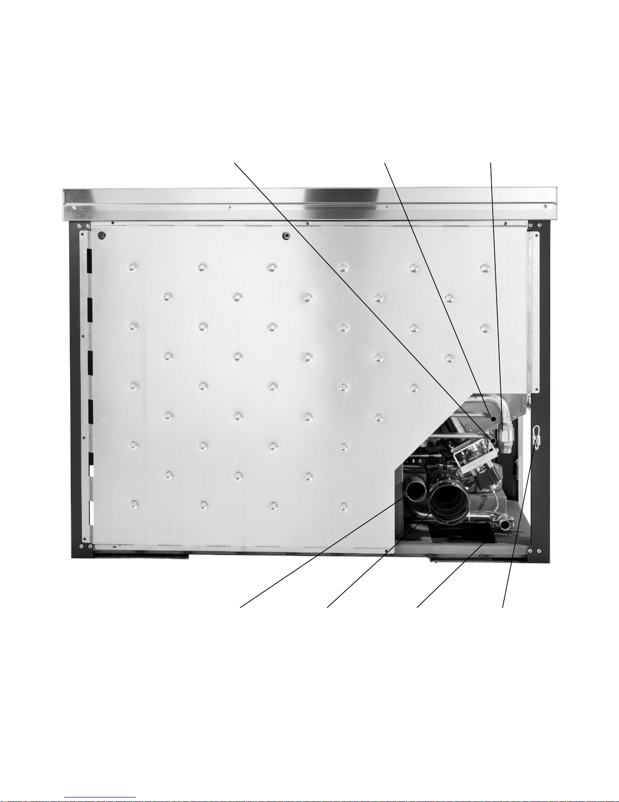
WARNING: the central heating cooker is supplied with already connected power supply cable to antidisturbance filter.
AIR VENT MANUAL
VALVE
ANTI-DISTURBANCE
FILTER WITH 2
INCORPORATED
FUSES
(4A 250V) AND
ATTACHMENT FOR
POWER SUPPLY
CABLE
SAFETY VALVE
CALIBRATED AT
2.5 BAR
POWER
BOARD
TECHNICAL
COMPARTMENT SIDE
Page 12
12
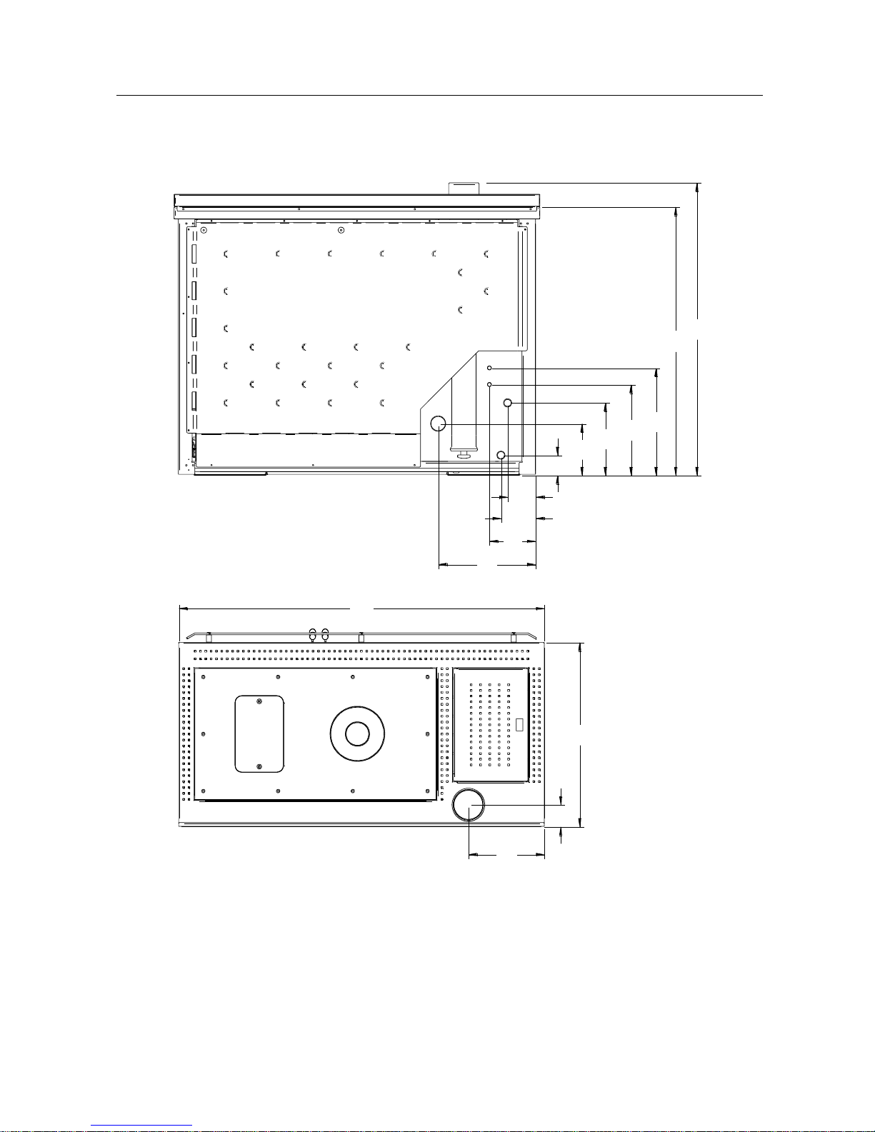
ROOM
THERMOSTAT
CONNECTION
CLAMP
AIR INTAKE PIPE
FLUE
EXHAUST
RETURN
ATTACHM
ENT
DOMESTIC COLD
WATER INLET (ONLY ON
MOD. WITH SET-UP)
+ SYSTEM LOAD AND
BOILER BODY
DOMESTIC HOT
WATER OUTLET
(ONLY ON SET-UP
MOD.)
FLOW
CONNECTION
WITH CHECK
VALVE
Page 13
13
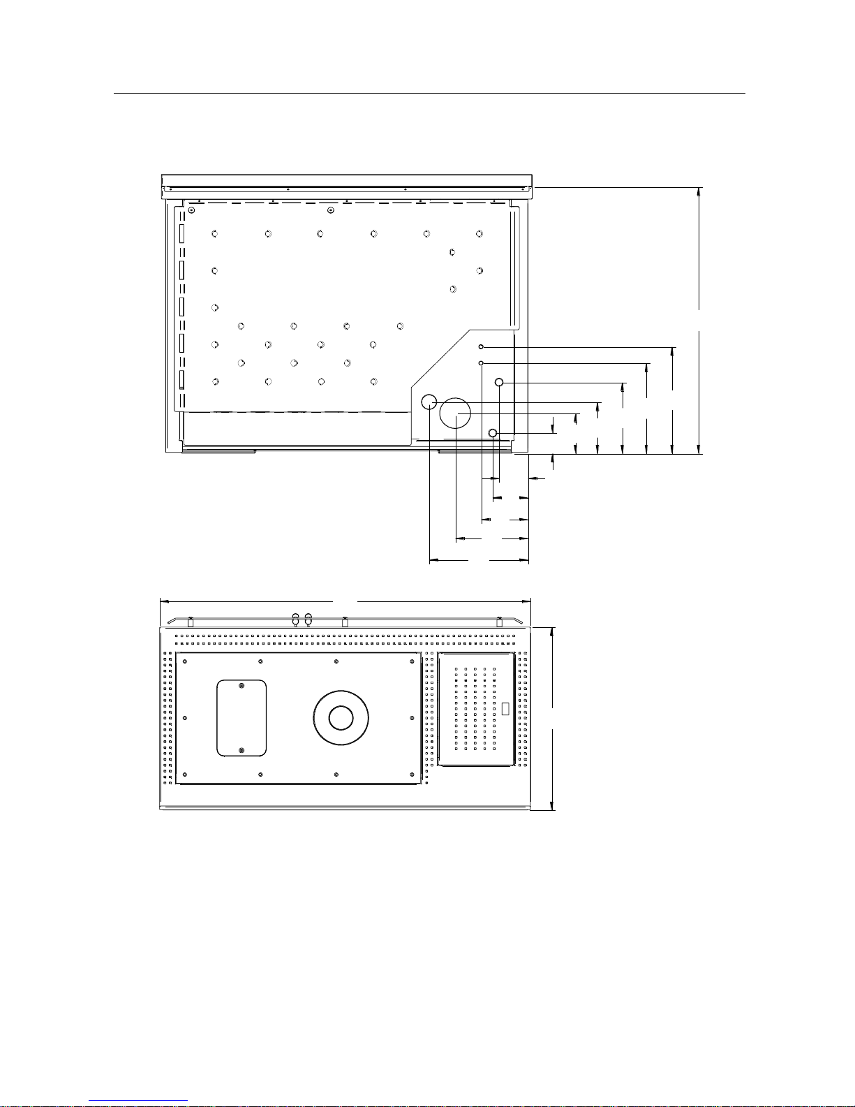
Connections data sheet (Model with upper flue gas outlet)
M = Ø ¾” F GAS SYSTEM FLOW
R = Ø ¾” M GAS SYSTEM RETURN
C = Ø 14 mm DOMESTIC HOT WATER OUTLET (on prepared models only)
F = Ø 14 mm DOMESTIC COLD WATER INLET
S = Ø 100 mm M FLUE OUTLET
A = Ø 50 mm AIR SUCTION DEVICE
955
250
70
350
295
235
65
170
320
150
115
90
M
R
F
C
A
S
1200
600
875
REAR
VIEW
Page 14
14
Connections data sheet (Model with rear flue gas outlet)
M = Ø ¾” F GAS SYSTEM FLOW
R = Ø ¾” M GAS SYSTEM RETURN
C = Ø 14 mm DOMESTIC HOT WATER OUTLET (on prepared models only)
F = Ø 14 mm DOMESTIC COLD WATER INLET
S = Ø 100 mm M FLUE OUTLET
A = Ø 50 mm AIR SUCTION DEVICE
350
295
235
170
65
320
150
115
90
235
130
M
R
F
C
A
S
875
1200
600
REAR
VIEW
Page 15

15
Technical features
Nominal heat input (reduced)
kW
25,2 (7,5)
Nominal heat output (reduced)
kW
22,7 (6,9)
Nominal heat output given-up to heating water (reduced)
kW
17,5 (4,5)
Nominal heat output given-up to the room (reduced)
kW
5,2 (2,4)
(Reduced) nominal output efficiency
%
90,1 (92)
CO at 13% oxygen at (reduced) nominal heat output
%
0,022 (0,044)
DHW production (Δt = 25°C)
l/min
10
Volume that can be heated at nominal power with a demand of 35 Kcal/m3 (45 Kcal/m3)
m3
560 (435)
Nominal voltage
V
220
Nominal frequency
Hz
50
Expansion vessel l/preloading bar
10 / 1
Maximum working pressure/recommended
bar
2,5 / 1,5
Minimum chimney draught at nominal input (reduced)
Pa
12,6 (10)
Combustion gas flow at nominal input (reduced)
g/s
16,2 (9,4)
Exhaust flue gas temperature at nominal input (reduced)
°C
145,1 (69,7)
Pellet tank capacity
Kg
32
Pellet min – max hourly consumption
Kg/h
1,2 – 5,1
Operation autonomy at minimum – maximum input
h
27 – 7
Boiler body capacity
l
24
FLOW/RETURN heating pipe connections
Ø
3/4” / 3/4"
Domestic water pipe connections
mm
14
Minimum safety distance from flammable materials
mm
200
Flue pipe diameter
mm
100
Width
mm
1200
Height
mm
880
Depth
mm
600
Weight
Kg
290
The manufacturer reserves the faculty to make any modifications to the product in order to improve its
performance.
The given heat output can change according to the pellet used.
Page 16

16
Pellet features
The central heating cooker has been tested with all types of pellets available on the market. The
pellets used must have the following features:
Diameter 6 mm;
Maximum length 35 mm;
Maximum humidity content 8 – 9 %;
100% wood. Total absence of additives.
1.1 % maximum ash residue
For a good performance of the central heating cooker, we recommend using good quality pellets.
Pellets should be poured into the tank using a shovel, and not directly from the bag.
To recognise good quality pellet, make sure:
It is made up of constant diameter cylinders, and has a smooth, glossy surface;
There is not a lot of sawdust inside the packaging;
If the pellet is poured into a container full of water, it will sink if it is good quality, and
it will tend to float if it is not;
The references of quality certifications and in particular compliance with
international standards such as EN 14961-2 Wood pellet class A1-A2 (maximum
moisture level of 10%), should be indicated on the packaging;
Packages are intact as pellet tends to absorb humidity. Humidity not only reduces
the calorific value and increases flue gas, but swells the product, which could create
problems in the central heating cooker.
International standards must be complied with for pellet manufacture as already happens in
France, Austria, Germany, and recently some Eastern countries, which also have to comply with
DIN 51731 and O-NORM M7135 standards in the production phase. These standards establish the
minimum values to check pellet quality. In Italy there are not official rules, but it is recommended
using pellet meeting the previously-mentioned standards.
The use of poor pellet or any other material can damage the central heating cooker features,
voiding the warranty and exempting the manufacturer from all responsibility.
In order to ensure problem-free combustion, the pellets must be kept in a dry place.
Page 17
17
REQUIREMENTS OF THE PLACE OF INSTALLATION
Positioning
The first step to ensure the best installation of the central heating cooker is to identify an excellent
location; in this regard, take the following elements into account:
The possibility of creating an external air intake;
The possibility of creating a straight flue with possibly coaxial central heating cooker
output;
Proximity to the main liquid collector and /or the boiler if one already exists);
Proximity or ease of connection to the water system;
Ease of access for cleaning the central heating cooker, the exhaust gas ducts and the
flue.
The central heating cooker must be installed on a floor with suitable load capacity. If the existing
building does not meet this requirement, appropriate measures (e.g. load distribution plate) must be
taken.
Once you have found the best location for the cooker arrangement, position it following the directions
given below.
The minimum safety distance from flammable materials must be at least 200 mm from the sides
and back of the central heating cooker.
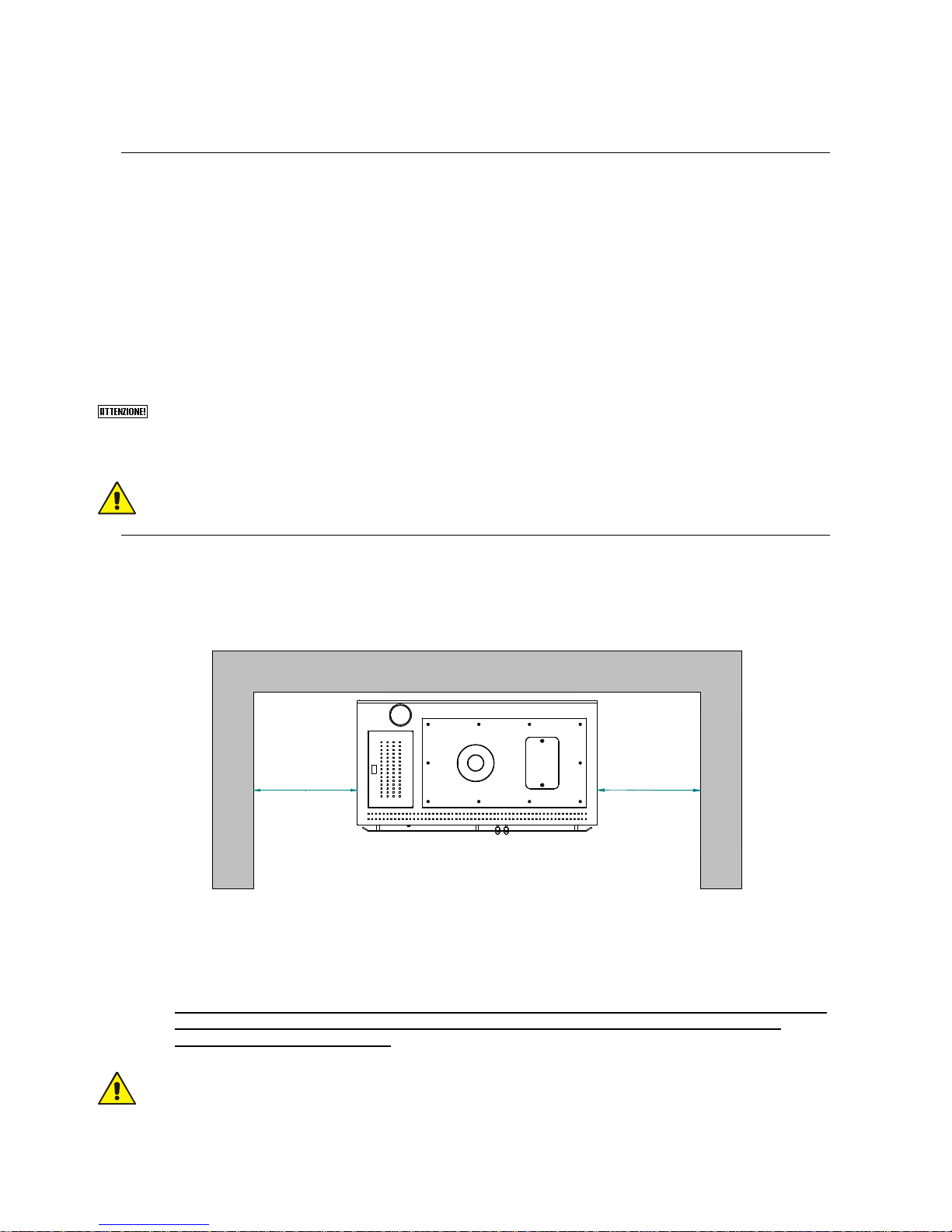
Spaces around and above the central heating cooker
The figure below shows the minimum measures to be met when positioning the central heating
cooker in relation to the walls.
PARETE POSTERIORE
PARETE LATERALE
PARETE LATERALE
50 cm
50 cm
The hood assembled above the central heating cooker must be at least 70 cm away from its upper
part (also see technical features in the instructions manual attached to the hood to be installed).
Furniture and mobile objects must be positioned at least 10 cm away from the equipment side walls;
these items should be easily removable in case of maintenance work. In any case they should
be moved before any operation by the authorised Technical Assistance Centre for easy
access to the equipment sides.
Hanging shelves or building countertops above the central heating cooker, especially if the latter
have low heat resistance, is not recommended. Shelves or countertops should in any case be at
least 70 cm away from the upper cooking plate.
Protect all structures that can catch fire from heat radiation.
REAR WALL
LATERAL WALL
LATERAL WALL
Page 18

18
External air vent
While running the central heating cooker draws air from the room in which it is installed; It is
essential, therefore, that the air is restored through an external air vent.
An air vent must be made at the back of the equipment (15 cm diameter hole), at a height of
20 cm from the ground, near the central heating cooker intake pipe (see figure A and
Connections technical sheet).
if the rear external air vent does not draw air directly from outside the home, a further hole in an
adjacent room must be made provided it communicates with the outside of the home (minimum
diameter 15 cm).
If an air vent cannot be made on the heating cooker rear wall, keep it at least 5 cm away from the
rear wall and drill a hole (diameter as above) in a perimeter wall of the room where the central
heating cooker is installed.
The hole must be protected externally with a fixed grid. Periodically ensure the grid is not
obstructed by leaves or the like, thereby preventing air passage.
The UNI 10683 standard PROHIBITS the withdrawal of combustion air from garages, fuel
stores, or businesses involving a fire hazard.
Do not connect the external air vent to the central heating cooker through piping. If there are
other heating or suction appliances in the room, air vents must ensure the necessary air
volume required for the proper operation of all devices.
In the room where the central heating cooker is to be installed, only sealed equipment (e.g. C
type gas equipment, according to the UNI 7129 Standard), or equipment that does not cause
depression with respect to the external environment can be kept or be installed.
Extractor fans may cause a malfunction in the central heating cooker when used in the same room
or operational space as the cooker.
Figura A
Flue and connection to the same flue - Chimney
The flue is a key element for the proper operation of the central heating cooker. The minimum section
of the flue must be the one indicated in the central heating cooker specifications (120 mm). Each
central heating cooker must have its own flue, without other intakes (boilers, fireplaces, stoves,
etc…). The flue size is closely related to its height, to be measured from the central heating cooker
outlet to the chimney base. To ensure draught, the chimney flue outlet surface must be twice as big
as the flue section.
Page 19
19
The exhaust duct of the combustion products, generated by the forced draught unit, must meet the
following requirements:
Be airtight to combustion products, waterproof, and properly insulated according to the
conditions of use (see UNI 9615);
Being made of materials suitable to resist normal mechanical stress, heat, action of the
combustion products, and condensate if any;
Have ascending development after the vertical tract for the entire remaining path with a
5% minimum slope. The sub-horizontal development part must not have a length greater
than ¼ of the effective height of the flue or chimney, and in any case not be longer than
2,000 mm;
Have a preferably circular internal section: square and rectangular sections should have
rounded corners with a radius larger than 20 mm;
To have constant, free and independent internal section;
To have rectangular sections with a 1.5 maximum ratio between sides;
If the flue is installed outdoors or in a cold room (e.g. boiler room) it is absolutely
necessary that it is insulated to prevent cooling of the fumes and the formation of
condensate;
To mount exhaust channels (stretching from the unit to the flue inlet), elements of non-
combustible materials suitable for resisting combustion products and any condensation
must be used;
It is forbidden to use fibre cement pipes to connect the appliances to the flue;
Exhaust channels must not pass through rooms in which the installation of combustion
appliances is forbidden;
When mounting exhaust channels, make sure they are flue gas sealed;
Installation of horizontal sections should be banned;
The usage of elements in counter-slope is forbidden;
The exhaust channel must allow soot recovery or cleaning using a swab, and must have
a constant section;
It is forbidden to run other air supply channels and pipes for plant engineering use into the
exhaust channels, even if oversized.
The chimney is a device crowning the flue, used to facilitate the dispersion of combustion products.
It must meet the following requirements:
Have a useful outlet section not smaller than twice that of the flue on which it is inserted;
Be shaped so as to prevent the penetration of rain and snow into the flue;
Be built in such a way that combustion discharge is ensured even in case of wind in any
direction and angle.
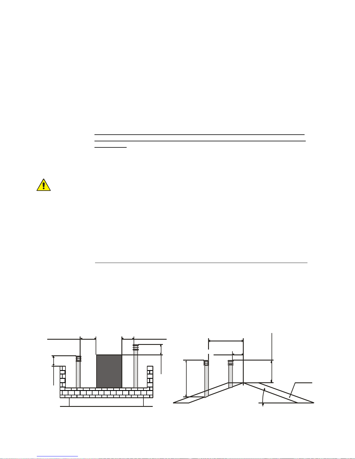
The outlet height (where height corresponds to the top of the flue, regardless of any chimneys) must
be beyond the so-called reflow area in order to avoid the formation of counter-pressures preventing
the free discharge of combustion products into the atmosphere.
It is therefore necessary to ensure compliance with the minimum heights shown in the following
figures:
Technical
volume
0,5 m
0,5 m
Distance > 5 m
Distance < 5 m
Distance> 1,85 m
Distance< 1,85 m
0,5 m over
the ridge
Reflow zone
1m m inimum
15°
Page 20
20
FURTHER SPECIFICATIONS TO BE CONSIDERED
The central heating cooker works with the combustion chamber in depression; it is essential that the
exhaust pipe is hermetically sealed.
We recommend using rigid stainless steel pipes, with sealing gaskets having a minimum diameter of
120 mm.
The pipes must be double-walled or adequately insulated with rock wool. The maximum
temperature of the pipe must not exceed 70 °C.
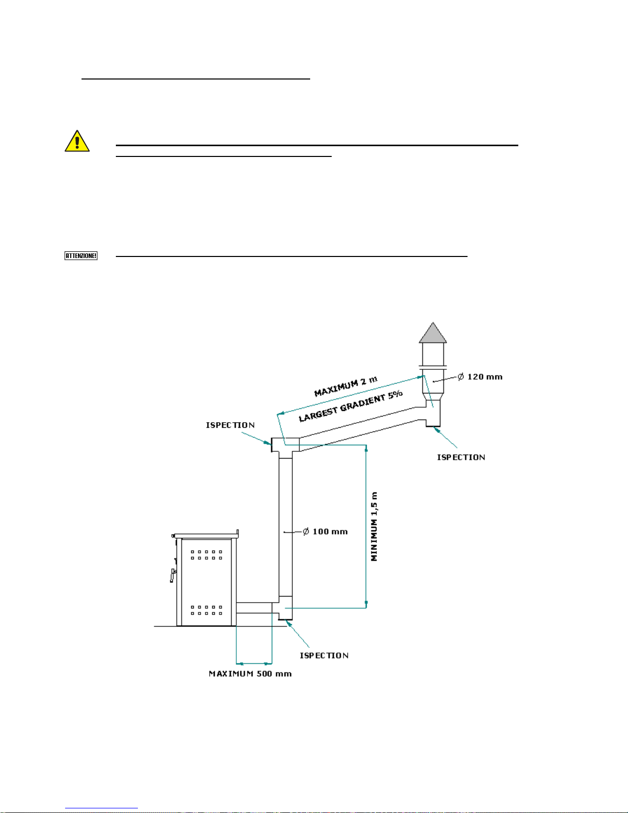
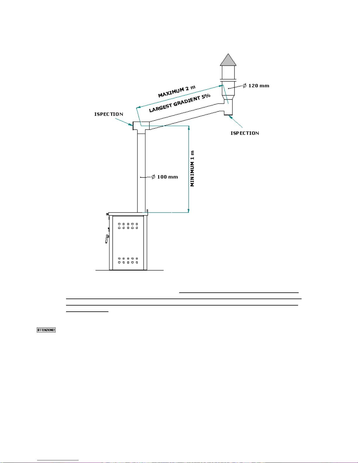
TO ENSURE PROPER FUME DISCHARGE PROVIDE FOR AN INITIAL VERTICAL TRACT OF AT
LEAST 1.5 METRES.
Each change of direction must be carried out with a T-shaped fitting and inspection cap.
Pipes must ensure sealing against smoke leakage via gaskets resistant to 250 °C.
Fix the pipes to the wall with suitable relevant metal collars to avoid any vibration.
WARNING: IT IS FORBIDDEN TO INSTALL DRAUGHT REGULATING VALVES (BUTTERFLY
VALVES).
There are two solutions for the connection to the flue:
SOLUTION 1 – REAR FLUE GAS OUTLET
Page 21
21
SOLUTION 2 – UPPER FLUE GAS OUTLET
If a “conventional” flue is used to discharge flue gas, make sure it is in good working order and
complies with the standards currently in force. If the flue should be too big (internal diameter
greater than 14 cm), duct the flue using a stainless steel pipe, properly insulated with rock
wool or vermiculite, and sized according to the route. The connection to the flue must be
properly sealed.
When mounting the flue, do not make more than 4 changes of direction, including the initial T-
shaped fitting. The maximum allowable length of the horizontal tract is 2 metres. Before
carrying out horizontal movements, make a vertical, at least 1.5 metre-long tract.
Page 22
22
ELECTRICAL CONNECTION
The electric connection must only be performed by qualified staff, in compliance with all general and
local safety standards.
Check that the power supply voltage and frequency correspond to 220V – 50 Hz.
Product safety is obtained when it is properly connected to an efficient earthing system.
When connecting to the mains power supply, provide a differential magnetic circuit breaker 6 A – Id
30 mA switch with an appropriate breaking load. Electric wiring including grounding must be
performed after removing the mains power supply.
When building the system, remember that cables must be laid in an unmovable way and away from
parts subject to high temperatures. During the final wiring of the circuit, only use components with an
appropriate degree of electrical protection.
KLOVER srl disclaims all liability for damage to people, animals, or property resulting from
failure to properly ground the central heating cooker in compliance with IEC standards.
The electronic control unit manages and controls all the central heating cooker features ensuring
excellent operation of the entire equipment at any time.
Inspection of a possible coupled boiler
If the Smart 120 central heating cooker is to be coupled with a previously installed boiler in the
system (e.g. wall-hung gas boiler), it must be ensured that when the pellet central heating cooker
takes over doing the heating the boiler stops. This is to make sure that you do not have to add up the
heat output in the two appliances installed in the system. This is why our set-up intervenes on the
coupled boiler when the pellet central heating cooker heating pump starts. In this way, there will never
be two boilers operating simultaneously in the same system. The coupled boiler will however always
be used for the production of domestic hot water.
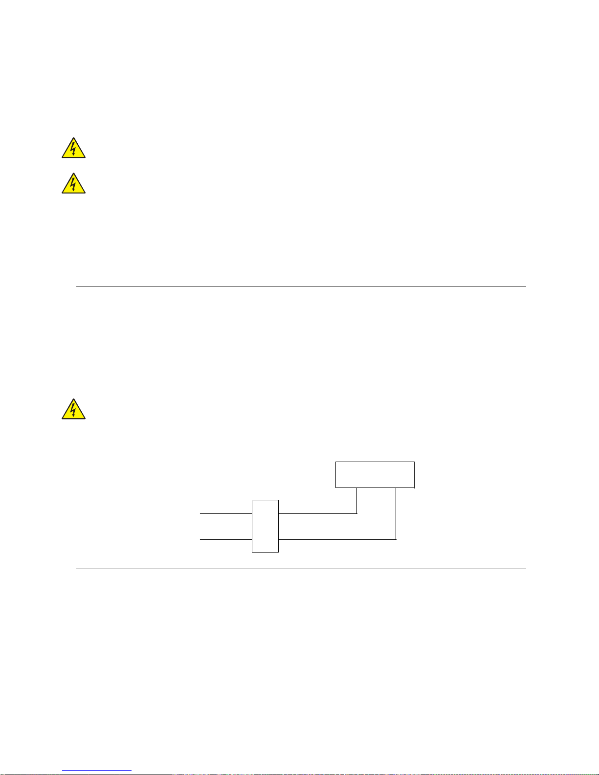
The two wires prepared on the back of the central heating cooker (blue and brown wires) will
have an output voltage of 220 V when the pellet central heating cooker pump is working, and
no voltage when the pump is at a standstill.
Therefore, it is easy to connect the 2 wires to a relay that will control the Room Thermostat inlet of the
coupled boiler.
RELAY
Boiler room
thermostat inlet
BLUE WIRE
BROWN WIRE
Control of a possible three-way motorized valve for the DHW system
The Smart 120 central heating cooker is equipped as standard with a control for a possible 3-way
motorized valve to be installed on the domestic hot water circuit. A 4-wire cable with protected faston
connectors 4 wires escapes from the rear part of the central heating cooker, which can be used to
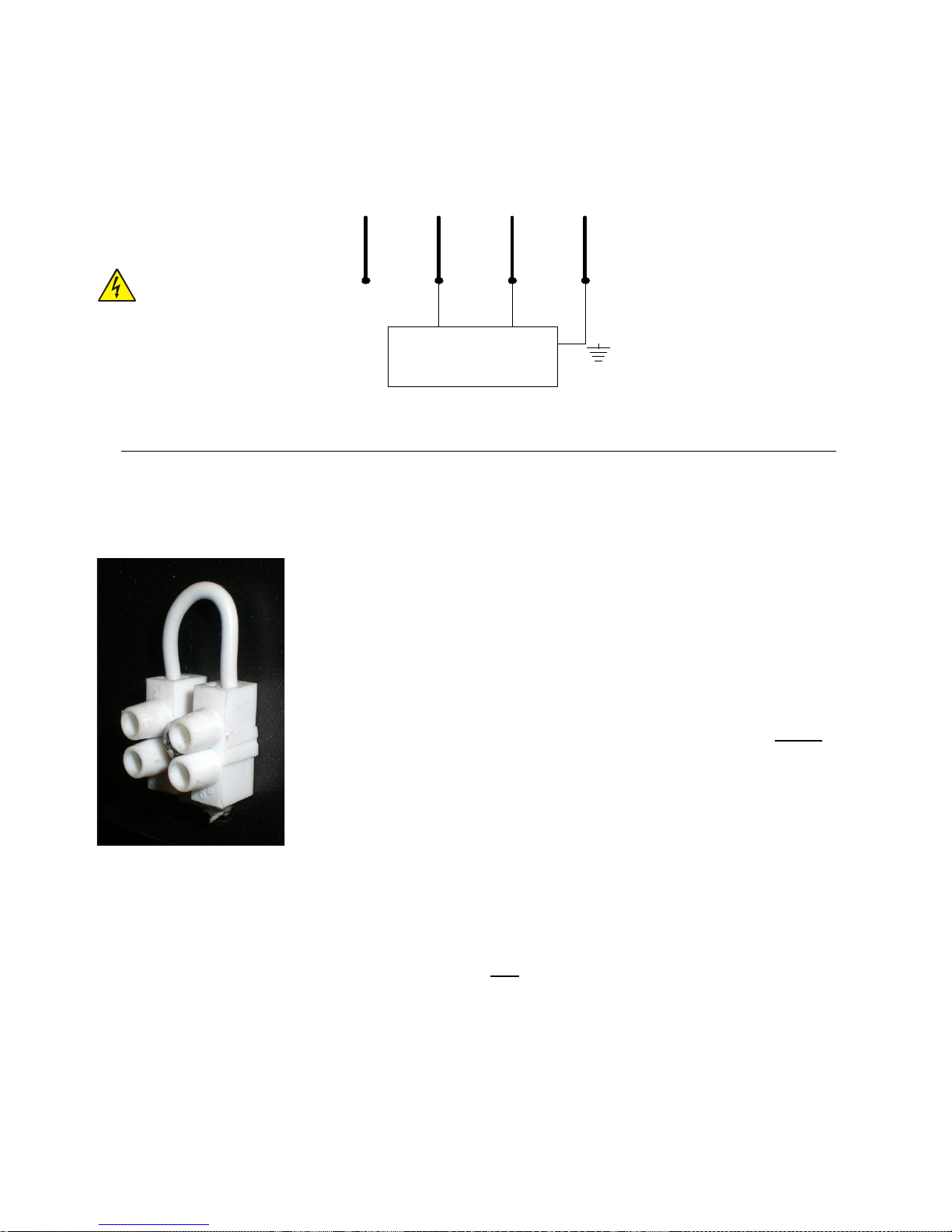
control this valve. The four wires in the cable have different colours, and precisely:
1. Blue wire = COMMON TO 3-WAY VALVE
2. Black wire = PELLET CENTRAL HEATING COOKER SIDE
3. Brown wire = GAS BOILER SIDE
4. Yellow/green wire = GND
Below find a connection example using a 3-way valve with spring return. Remember that the pipe
connection must be made in a way that when the valve is at rest, the water passes from the gas
Page 23
23
boiler. Only when the pellet central heating cooker temperature is sufficient (the value is set from
control panel) is the 3-way valve powered, and so closes the gas boiler circuit and opens the Smart
120 central heating cooker circuit.
BROWN WIRE
YELLOW/GREEN WIRE
BLUE WIRE
BLACK WIRE
3-WAY VALVE
NOTE: The brown wire can be used to control any service relay.
Connection to the room thermostat
A bridge clamp is installed on the rear of the central heating cooker (free contact), which is useful to connect
any room thermostat. In this way, connecting an external thermostat with the function to open or close the
contact depending on the heat demand will be easier.
OPERATION PRINCIPLE
Open contact:
1. The central heating cooker switched directly to economy mode operation “TOFF ECONOMY” minimizing working output.
2. The central heating cooker pump turns off.
3. The temperature in the central heating cooker increases due to thermal
inertia until reaching the temperature set on “SET H2O” and displaying “TH2O ECONOMY” on the screen.
4. The central heating cooker will now automatically switch off if there is at least
one of the following conditions:
If it remains in Economy mode operation “T-H2O ECONOMY” for a time
set on Pr44 (30-minute default setting).
If it exceeds the temperature differential set on Pr43 (factory set value
5°C) or H2O Temperature > (“SET H2O” + Pr43)
NOTE: The pump is calibrated to start at temperatures ≥ 83°C in all conditions (see parameter table).
WARNING: If a room sensor on the remote control is also enabled (see page 44 – “Menu 04”), the
central heating cooker enters the economy mode when both cases are satisfied.
The room thermostat operation is excluded if one of the three OVEN OUTPUT VALUE is set.
The central heating cooker will switch on automatically if both the following conditions occur:
If the contact of the room thermostat is closed.
If it goes below the temperature differential set on Pr43 (5°C default setting) or Temperature H2O <
(“SET H2O” – Pr43).
If the above-described condition occurs when the central heating cooker is still running the switch off cycle, it
is appropriate to wait until it runs out.
Page 24

24
PLUMBING CONNECTION
The plumbing connections must be made in a rational way using the connections on the central
heating cooker template. To facilitate the connection of the pipes, we have provided all plumbing
connections on the rear left side, leaving space to easily make the appropriate connections.
Remove the left side of the central heating cooker to access the “side technical compartment” (see
fig. on p. 10 and 34) to facilitate the plumbing connection.
The central heating cooker can be coupled to any other boiler already installed in the system
including all necessary safety devices and wiretaps according to the system used.
NOTE: The central heating cooker can be installed with a closed expansion vessel equipped
with a device for stopping fuel loading, a safety manual reset thermostat and an audible alarm
activated if temperatures are too high.
The central heating cooker can be installed in the same room as another boiler only if it has a
sealed chamber.
THE CENTRAL HEATING COOKER MUST BE INSTALLED EXCLUSIVELY BY QUALIFIED
ENGINEERS. STRICTLY COMPLY WITH THE INSTRUCTIONS GIVEN IN THIS GUIDE; FOR ANY
DOUBT CONTACT THE TECHNICAL ASSISTANCE CENTRE.
THE MANUFACTURER DISCLAIMS ALL RESPONSIBILITY FOR DAMAGE CAUSED BY
IMPROPER INSTALLATION.
THE NETWORK WATER INLET PRESSURE MUST NEVER EXCEED 3 BAR; RECOMMENDED
WORK PRESSURE: 1.2 BAR.
DO NOT PASS ELECTRIC CABLES IN THE IMMEDIATE VICINITY OF THE FLUE GAS PIPE,
UNLESS THEY ARE INSULATED WITH APPROPRIATE MATERIALS.
IN THE EVENT OF WATER WITH HARDNESS EXCEEDING 28 °f, AN ANTI-LIMESCALE DEVICE
MUST BE INSTALLED. THIS MUST BE SELECTED ON THE BASIS OF WATER
SPECIFICATIONS.
Page 25
25
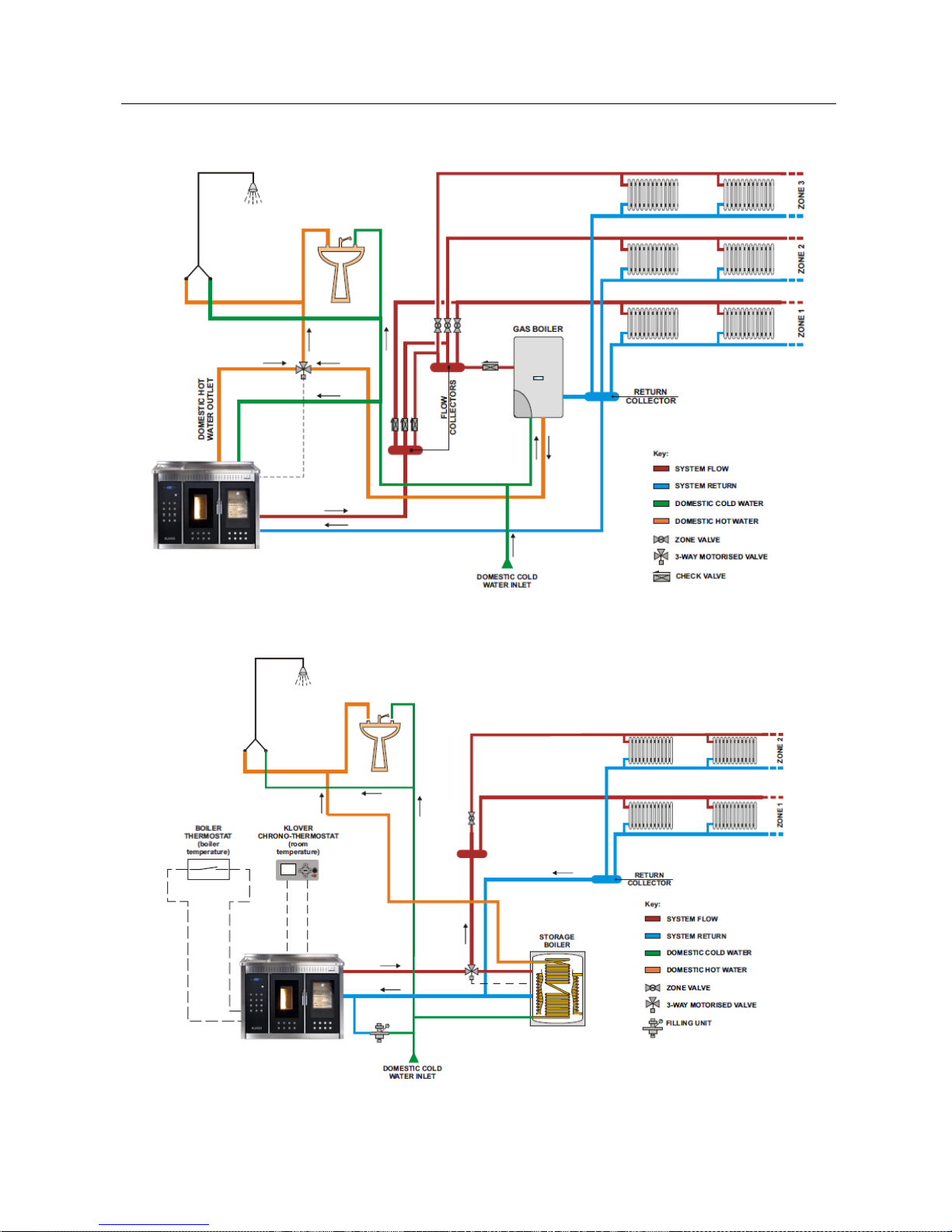
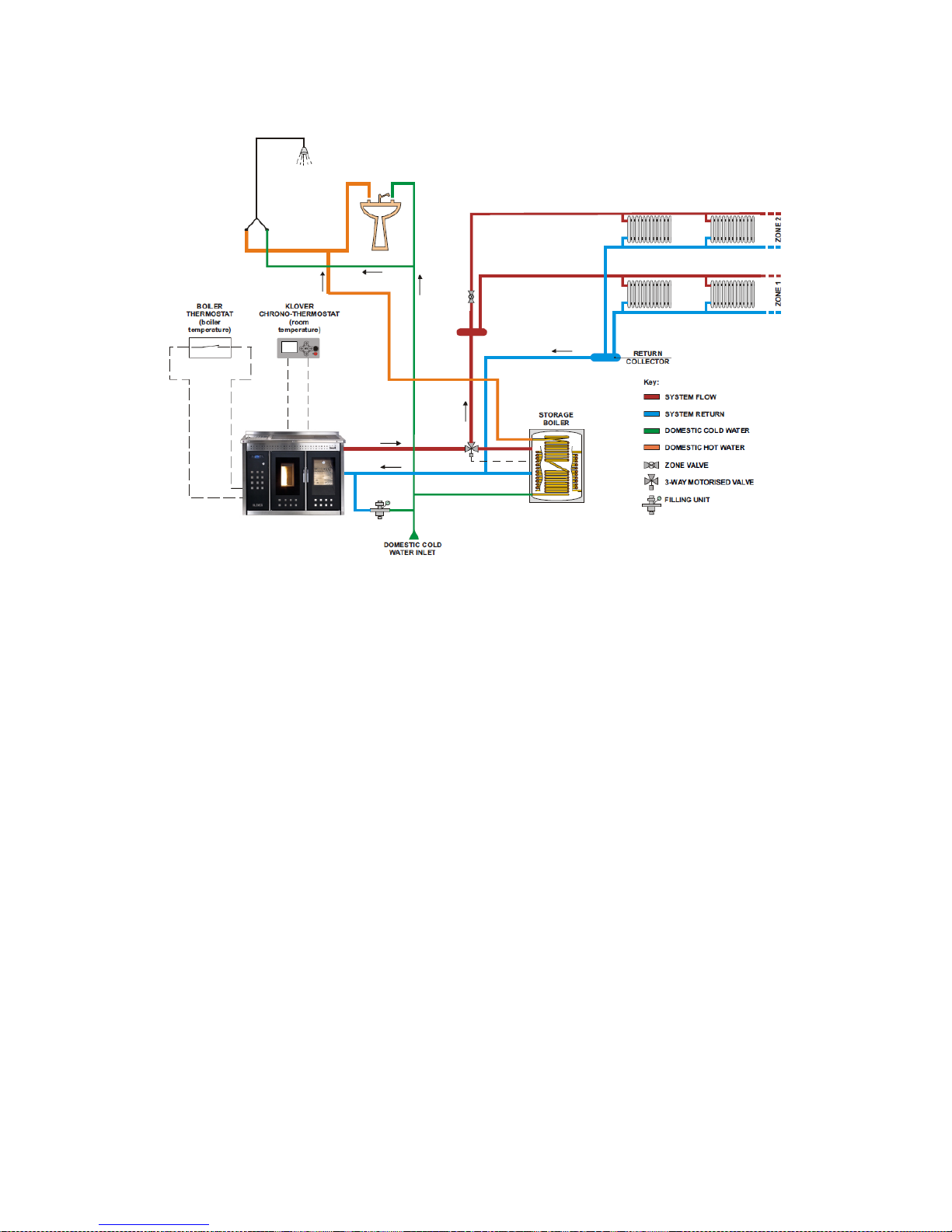
Connection examples
CONNECTION EXAMPLE WITH GAS BOILER COUPLING
-------------------------------------------------------------------------------------------------------------------------
CONNECTION EXAMPLE WITH DOMESTIC HOT WATER STORAGE COUPLING
These diagrams are for guidance only and do not imply any commitment or liability by KLOVER s.r.l. and its partners.
The final design and subsequent implementation will be carried out in strict compliance with regulations in force.
Page 26
26
CLEANING AND MAINTENANCE
Precautions before cleaning
Before carrying out any cleaning or maintenance, make sure that:
The central heating cooker is off and has cooled down completely;
Ash is completely cold;
Before re-starting the central heating cooker, re-install all previously disassembled parts.
For cleaning operations, personal protective equipment should be worn.i.e. gloves, goggles and dust
masks, as directed in eu 89/391/EEC.
Cleaning frequency depends on the type and quality of pellets burnt. Therefore, the schedule reported
below may vary.
Any central heating cooker problem resulting from failure to clean it will not be accepted as
collateral.
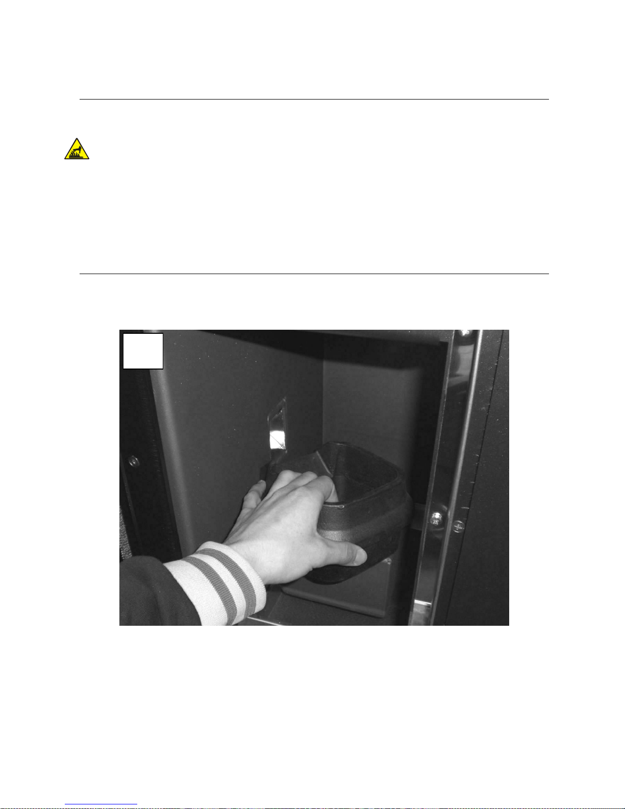
Routine cleaning (1)
The central heating cooker requires periodic cleaning to be carried out at least every 20 working hours or after
3-4 ignitions, to always ensure efficiency and excellent operation.
Carefully clean the brazier from combustion residues, by removing it from its seat.
1
1.1
Page 27
27
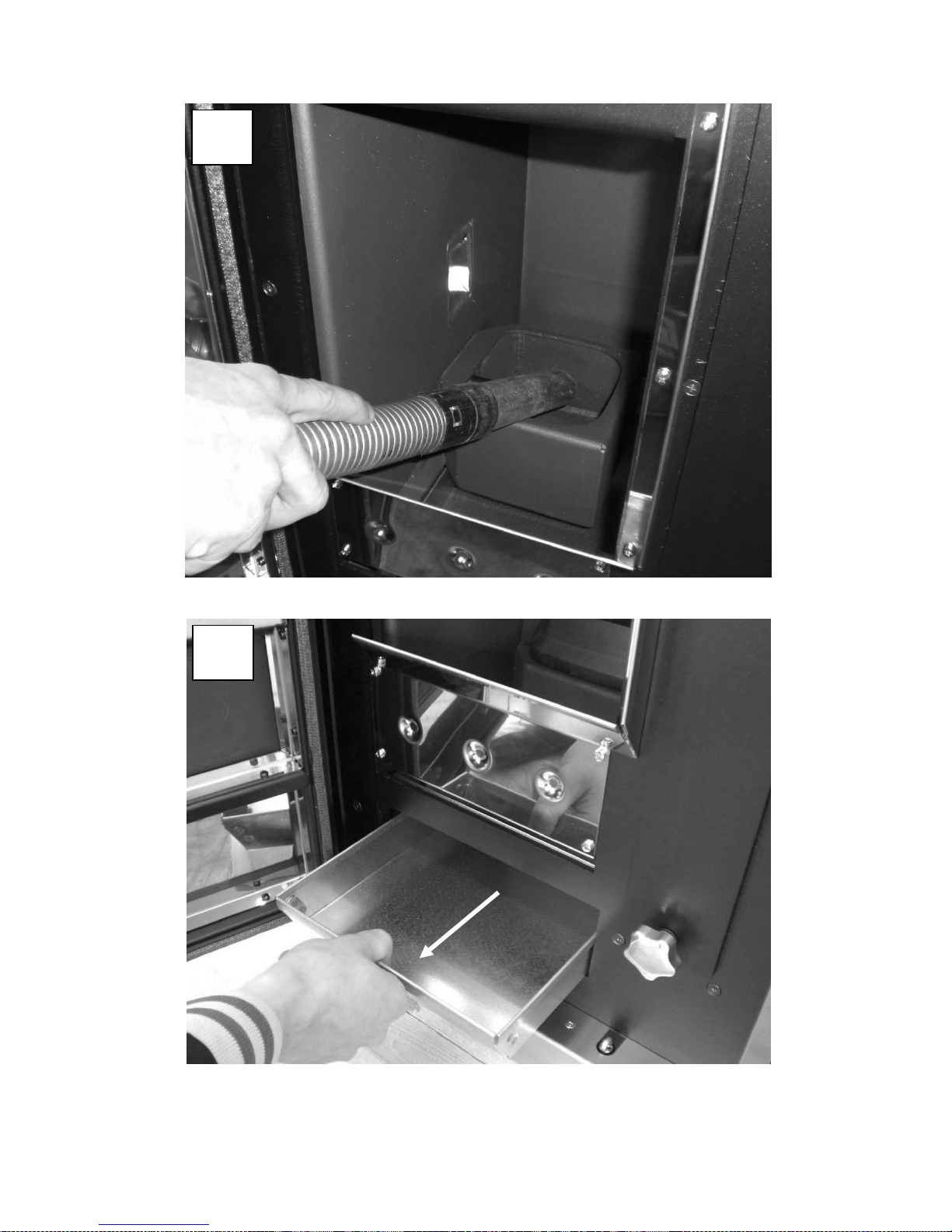
Use a vacuum cleaner to remove the ash that is deposited under the brazier.
Empty the ash drawer.
WARNING: Use suitable bin vacuum cleaners with a fine mesh filter to prevent part of the ash from being
discharged into the environment, and damaging the suction device itself.
1
2.1 1 3.1
Page 28
28
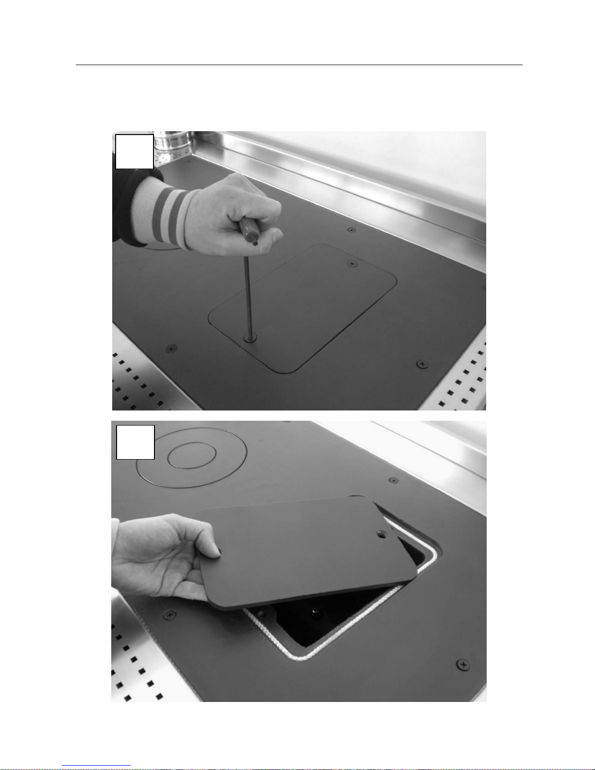
Extraordinary cleaning (2)
To be performed at least every 30 days.
Carry out routine cleaning;
2
1.1 2 1.2
Page 29
29
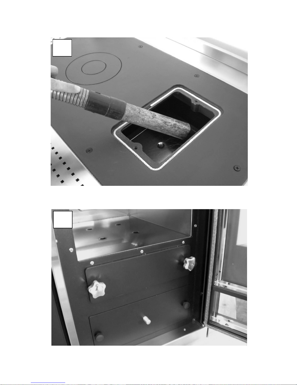
Dismantle the outlet on the cooking plate and suck the ash deposit above the oven. Properly re-position the
outlet after cleaning ensuring it is flue gas sealed.
2
1.3
2
2.1
Page 30
30
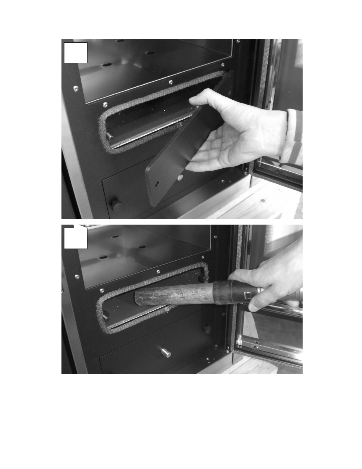
Dismantle the outlet underneath the oven and suck the ash deposit below it and on its side. Properly re-
position the outlet after cleaning, ensuring it is flue gas sealed.
2
2.2 2 2.3
Page 31
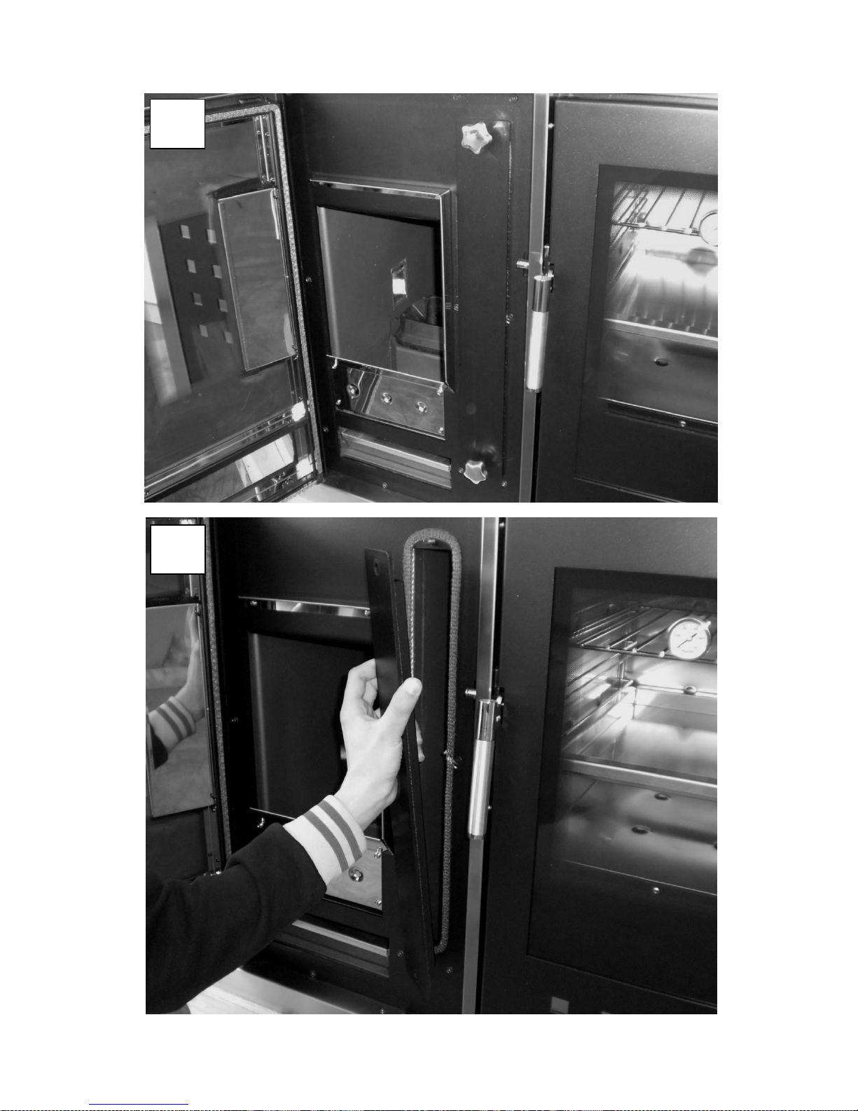
31
2
3.1 2 3.2
Page 32
32
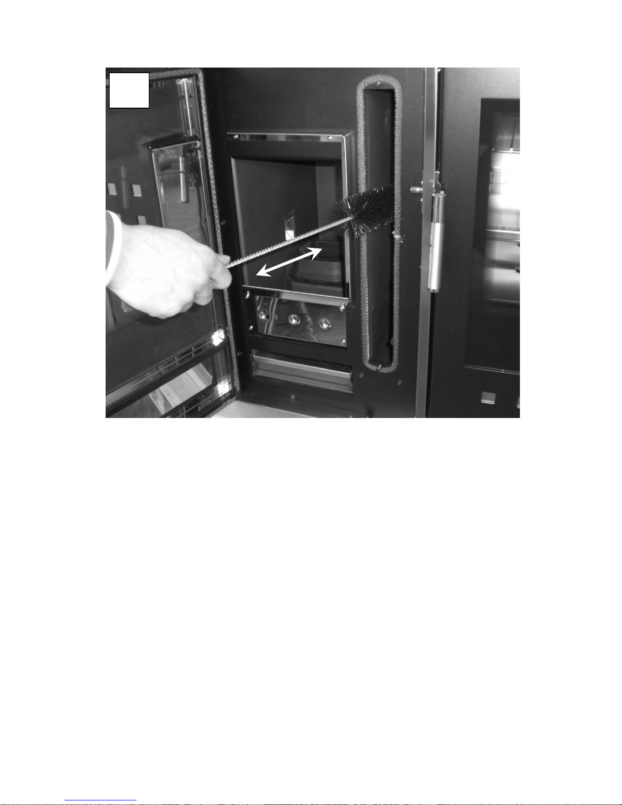
Dismantle the outlet side of the combustion chamber and clean the internal flue gas turn with the brush
provided with the equipment. Suck the ash deposit in the part below. Properly re-position the outlet after
cleaning, ensuring the outlet is flue gas sealed.
2
3.3
Page 33
33
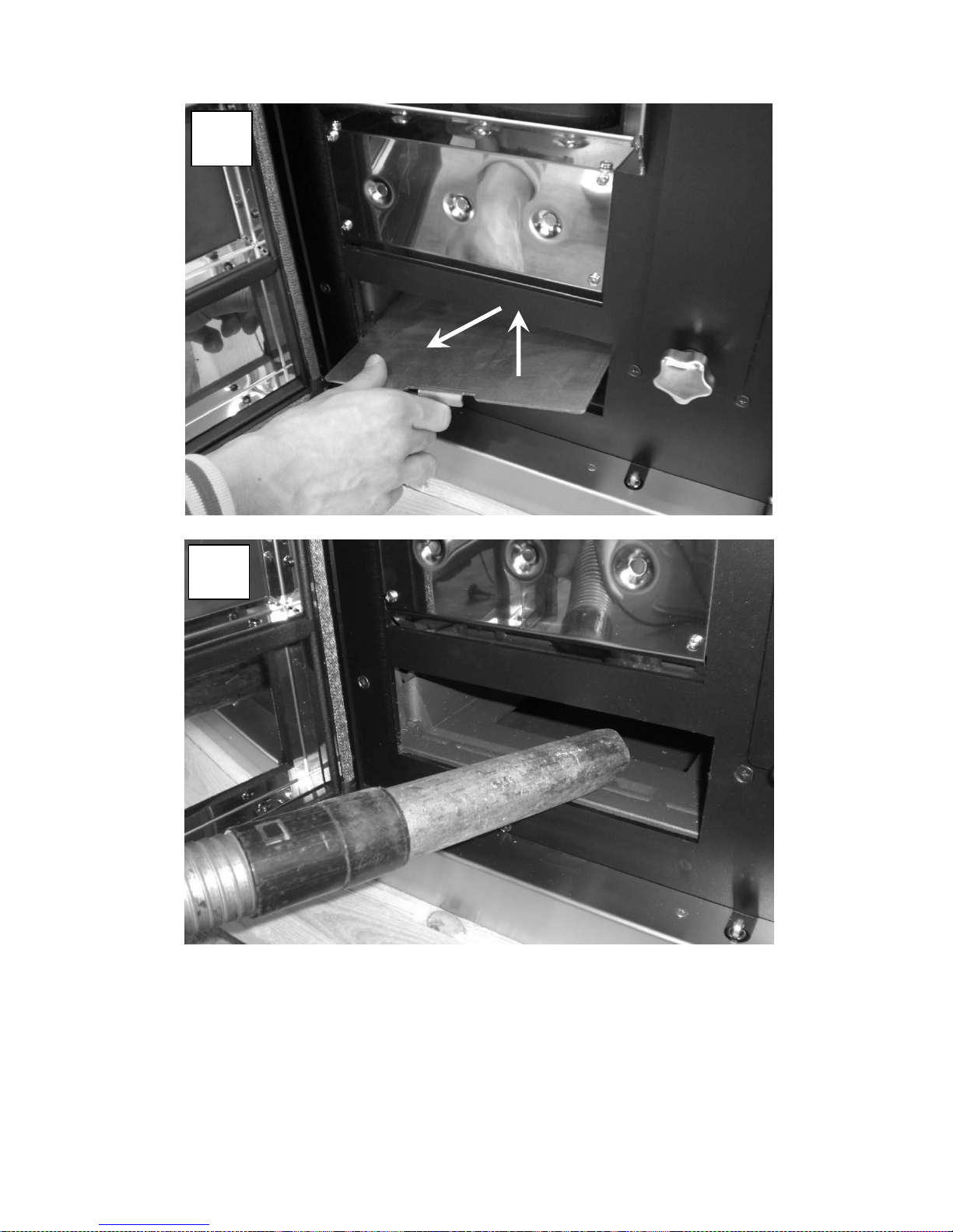
After removing the ash drawer, extract the underlying base and, using a suitable suction device, suck the
deposit inside. Then re-position the base and ash drawer.
1
2
2
4.1 2 4.2
Page 34
34
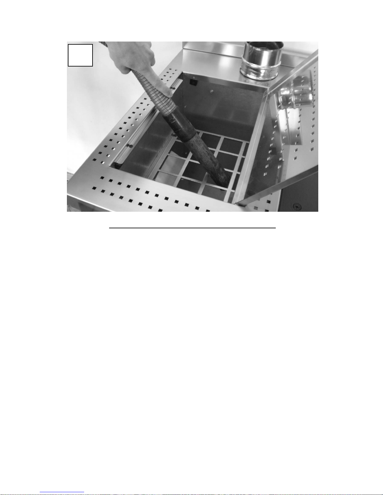
Suck the sawdust deposit from the tank base.
The pellet tank must be emptied at the end of every season.
2
5.1
Page 35
35
Yearly cleaning
To be performed at least once a year.
Carry out routine cleaning;
Carry out extraordinary cleaning;
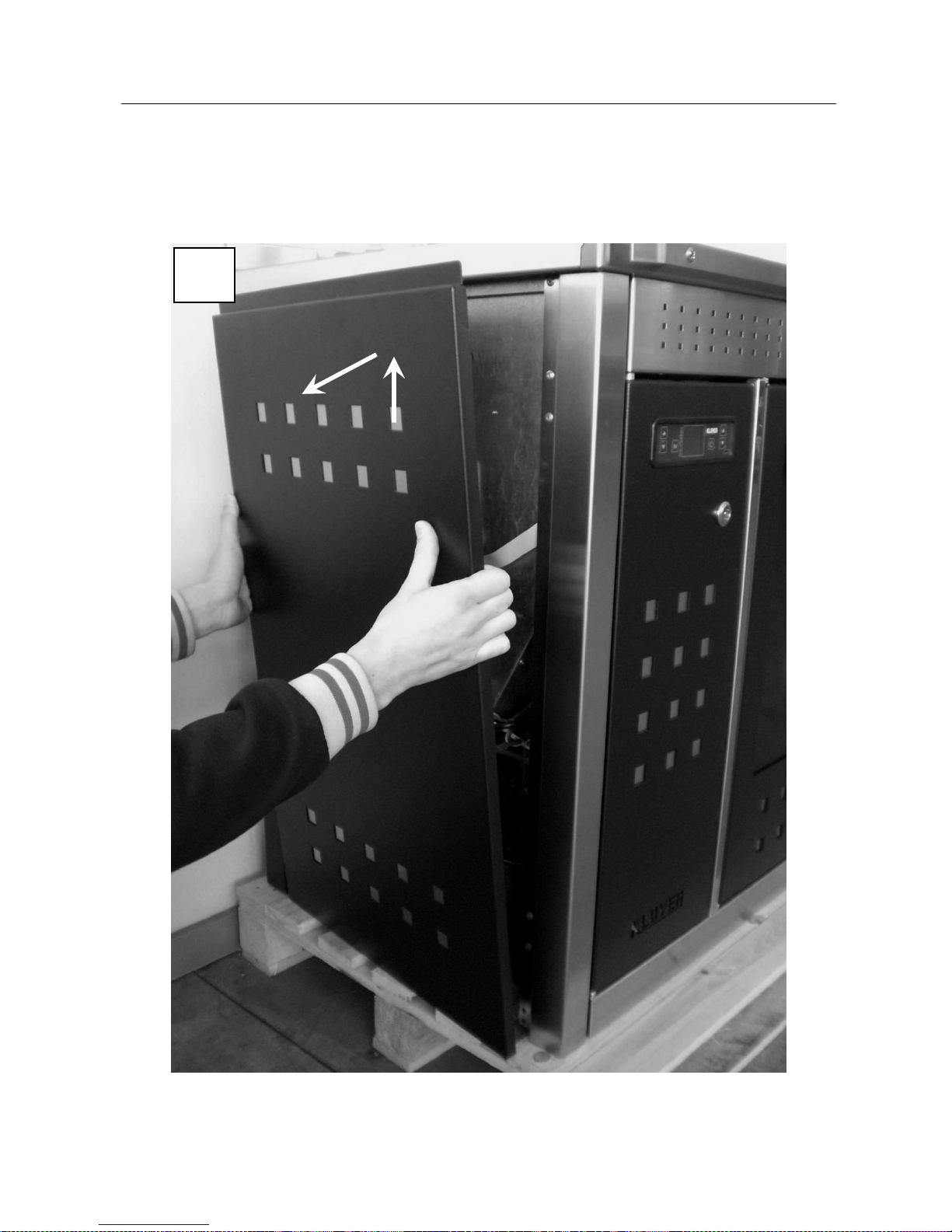
Remove the left side as in the above photo.
1
2
3
1.1
Page 36
36
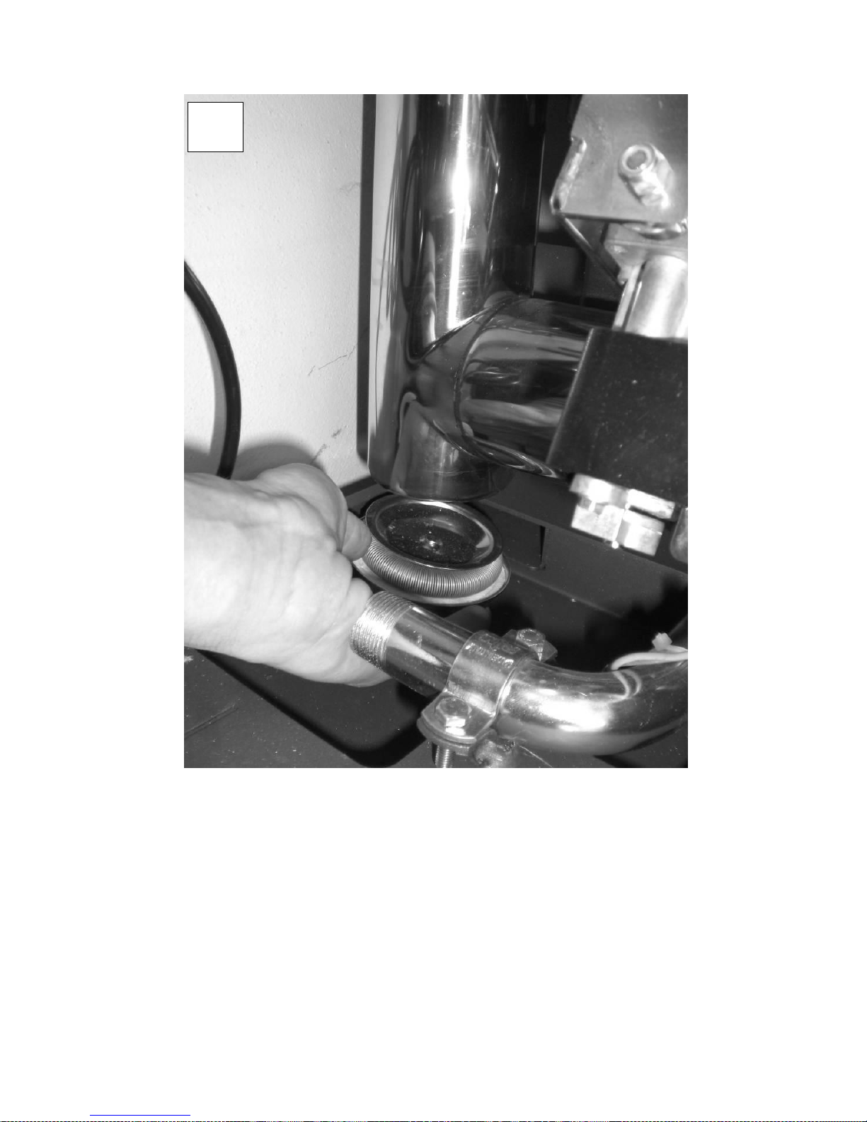
Remove cap from rear TEE and clean the entire flue pipe with a brush, sucking any soot deposit. Properly re-
position the cap after cleaning, ensuring it is flue gas sealed. The rear TEE is only available in models with
upper flue connection.
3
2.1
Page 37
37
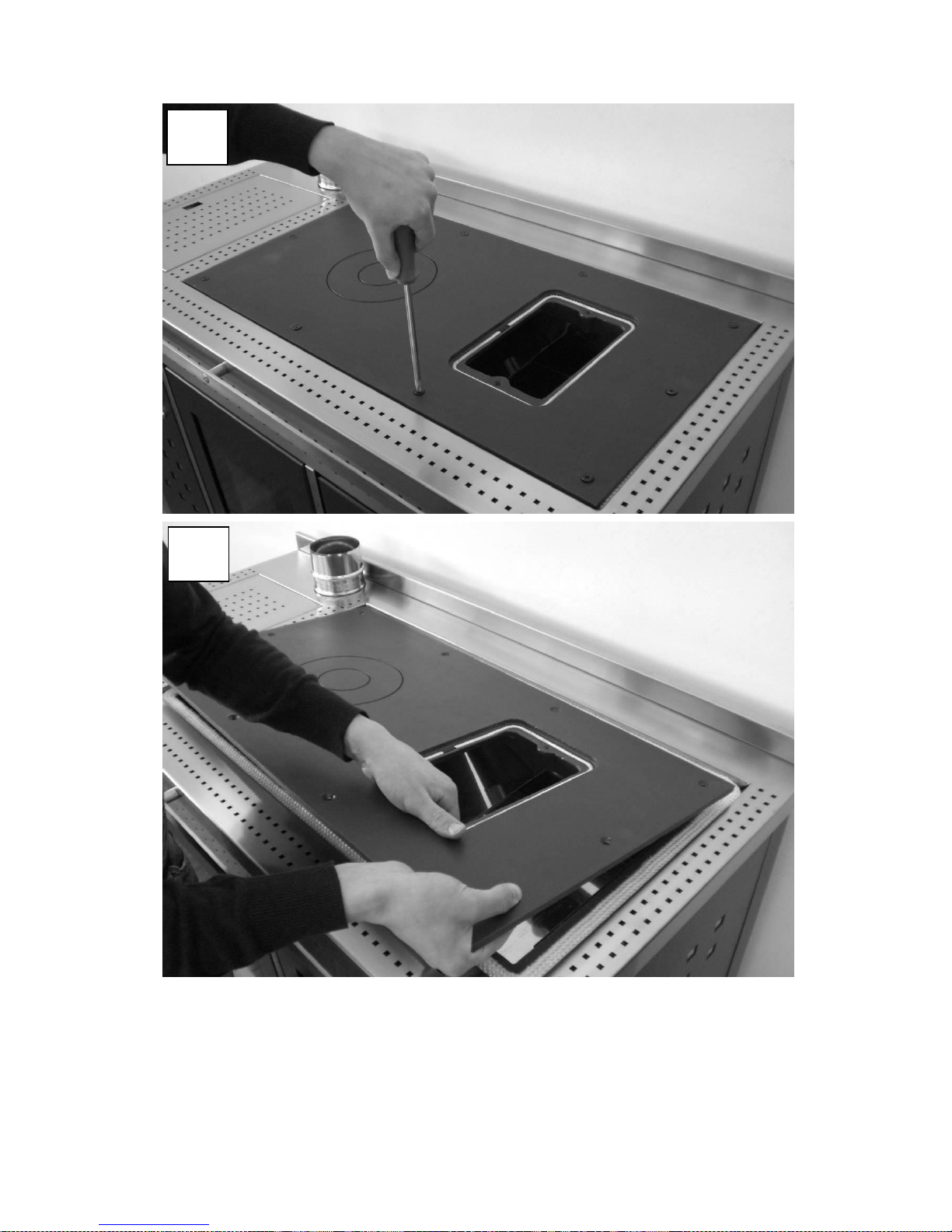
Remove the cooking plate by loosening the ten screws all around it after dismantling the upper cleaning
outlet.
3
3.1
3
3.2
Page 38
38
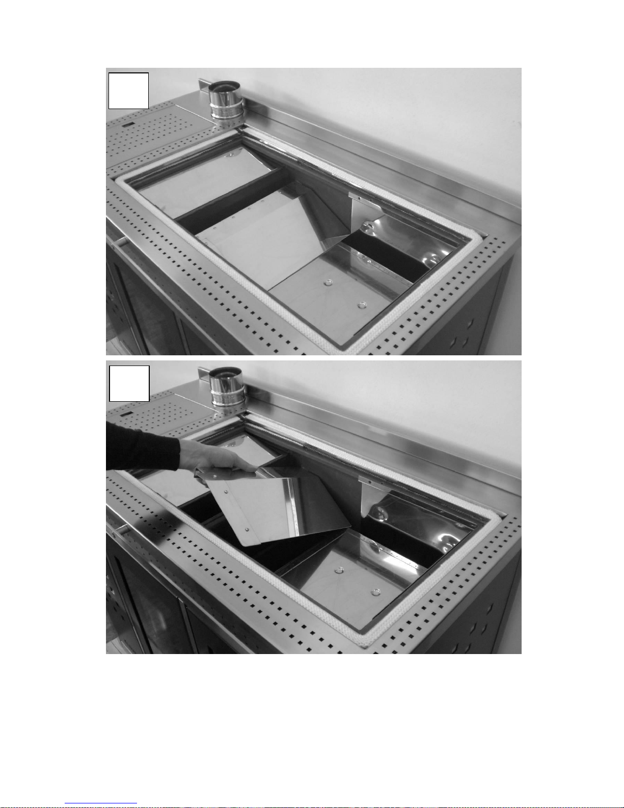
Remove the flue deflector located between the combustion chamber and the cooking oven.
3
4.1
3
4.2
Page 39
39
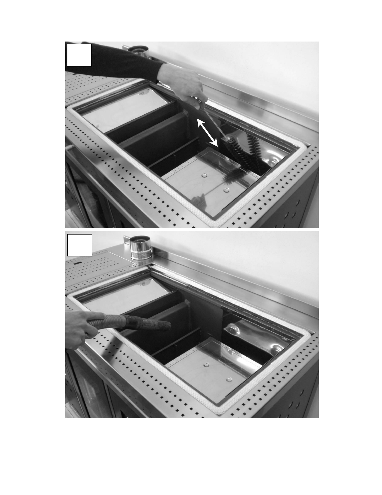
Scrape around the oven sides using the supplied brush, and vacuum any soot deposit. Re-position the flue
deflector and cooking plate after cleaning, ensuring the latter is flue gas sealed.
3
5.1
3
5.2
Page 40

40
Ceramic glass cleaning
Always clean the glass when the central heating cooker is off and completely cold. Use a damp cloth
and specific detergent for ceramic glass. Do not use abrasive sponges.
Flue cleaning
This operation must be performed at least twice a year, in early and mid winter, and whenever necessary.
You need to check for obstructions in the flue before switching the central heating cooker on, following a long
period of disuse.
If cleaning is not performed, the operation of the central heating cooker and its components may be impaired.
The frequency of the central heating cooker and flue cleaning depends on the quality of the pellets
used.
USE TOP QUALITY PELLETS TO OBTAIN THE BEST RESULTS.
Maintenance
Systematic, timely maintenance is a critical component for correct operation, excellent thermal performance
and duration of the appliance over time. Therefore, it is recommended that a qualified engineer checks the
central heating cooker at least once a year at start of season.
It is advisable to agree an annual contract for product maintenance with the Authorised Technical
Assistance Centre (TAC).
Page 41
41
THE DISPLAY
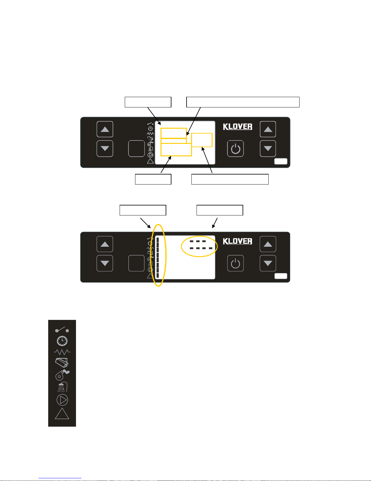
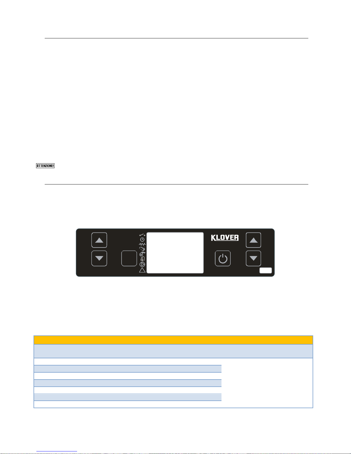
The console displays information about the operation of the unit. By accessing the menu, you can get
various types of displays and adjust the available settings depending on the selected menu.
The figure below shows the display when the unit is in on or off mode.
Set
!
1
2 3 4 5
6
Set
!
1
2 3 4
5
6
The figure below describes the meanings of the state signals appearing on the display left side (1st LED
SERIES).
!
ROOM THERMOSTAT: the LED lights up when the contact of the room thermostat is open.
CHRONO-THERMOSTAT: the LED lights up when at least one start-up and switch-off program is
active.
START-UP RESISTANCE: the LED lights up when start-up resistance is active.
SCREW CONVEYOR: the LED lights up when the pellet loading motor reducer is started.
FLUE GAS EXTRACTOR: the LED lights up when the flue gas intake device is active.
DHW FLOW SWITCH: the LED lights up when the DHW flow switch contact is closed (which
means there is demand for hot water). NOT USED ON THIS PRODUCT
PUMP: the LED lights up when the system circulation pump is active.
ALARM: the LED lights up when the boiler is in a state of alarm.
2nd LED
1st LED
17:19
- - - - 60°C
OFF
DIALOGUE
WATER TEMPERATURE
CLOCK
ROOM TEMPERATURE (optional)
Page 42
42
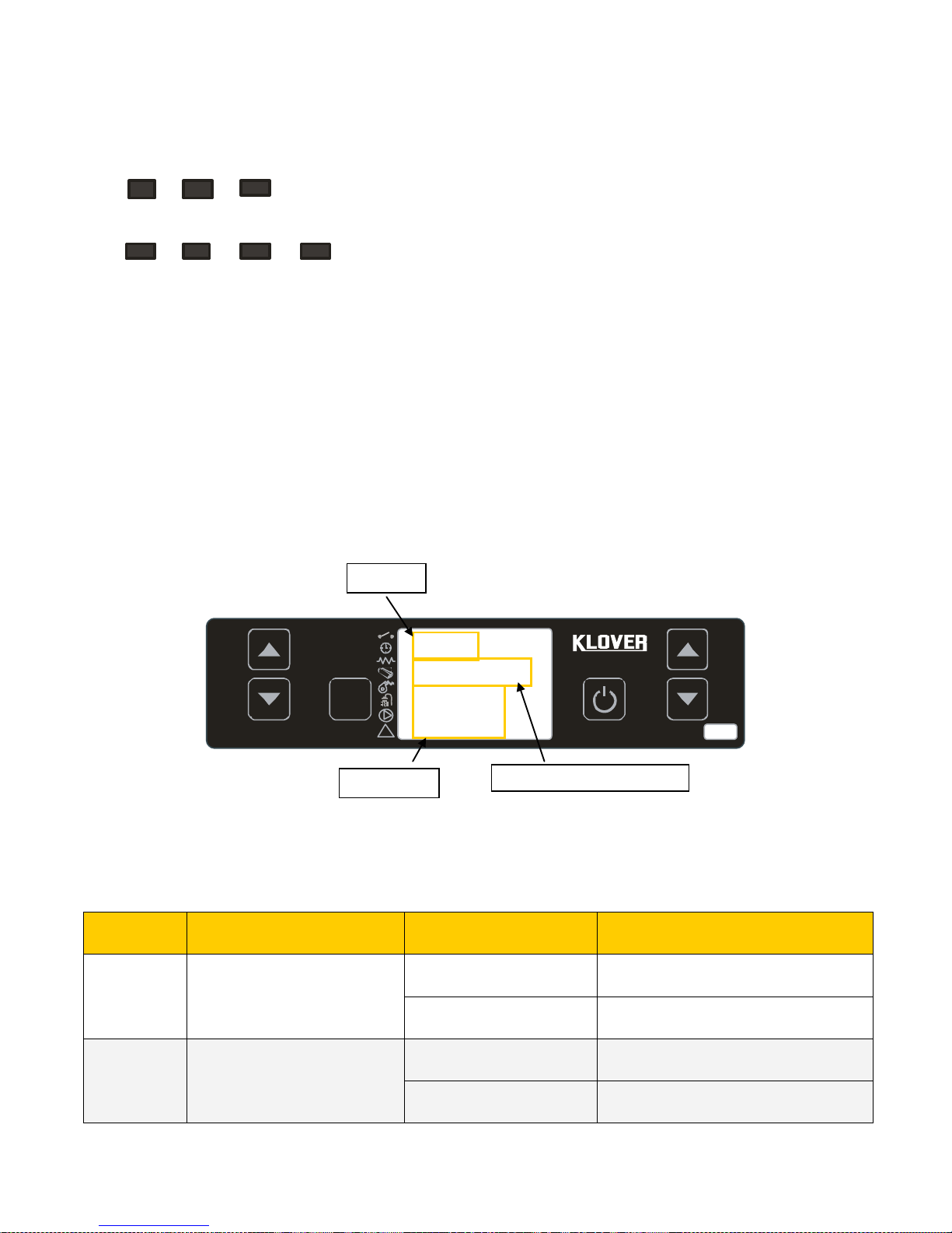
The figure below describes the meanings of the state signals appearing on the top right side of the display
(2nd LED SERIES).
1 – the LED lights up when the on off settings daily program is active.
2 – the LED lights up when the on off settings weekly program is active.
3 – the LED lights up when the on off settings week-end program is active.
4 – the LED lights up (flashing) when the operation parameters are being edited.
5 – the LED lights up when the summer function is active (NOT USED ON THIS PRODUCT).
6 – the LED lights up when the winter function is active.
7 – the LED is not currently used.
The following figure shows the display when setting or programming operating parameters.
Set
!
1
2 3 4 5
6
The INPUT area shows the entered programming values.
The MENU LEVEL area shows the current parameter/menu level.
The DIALOGUE area displays the current parameter/menu meaning.
BUTTON
DESCRIPTION
MODE
ACTION
1
It increases temperature (1)
Programming..
It changes/increases the value of the
selected menu.
Working/off..
It increases the temperature of the
room/water thermostat.
2
It decreases temperature (2)
Programming..
It changes/increases the value of the
selected menu.
Working/off..
It decreases the temperature of the
room/water thermostat.
1
2 3 4 5 6
7
On
M - 2 - 2 - 01
CHRONO
DAY
DIALOGUE
MENU LEVEL
INPUT
Page 43

43
3
Set
-
It accesses the selected menu.
In menu..
It accesses to the next level of submenus.
4
ON/OFF
Outlet
Working..
It switches on and/or off the central
heating cooker when pressed for 2
seconds.
In alarm block..
It unlocks the alarm.
In menu/programming..
It switches to the next submenu item by
storing the changes.
5
It decreases output (3)
Working/off..
It decreases the DHW thermostat
temperature value. It decreases the
central heating cooker working output.
In menu..
It moves to the next menu item.
Programming..
It switches to the next submenu item by
storing the changes.
6
It increases output (4)
Working/off..
It increases the DHW thermostat
temperature value. It increases the
central heating cooker working output.
In menu..
It moves to the previous menu item.
Programming..
It switches to the previous submenu
item by storing the changes.
(1) It selects WATER TEMPERATURE SET “SET H2O” when first pressed.
(2) It selects ROOM TEMPERATURE SET “SET ROOM” when first pressed.
(3) It selects DHW TEMPERATURE SET “SET DHW” when first pressed.
(4) It selects WORKING OUTPUT “SET OUTPUT” when first pressed.
Page 44
44
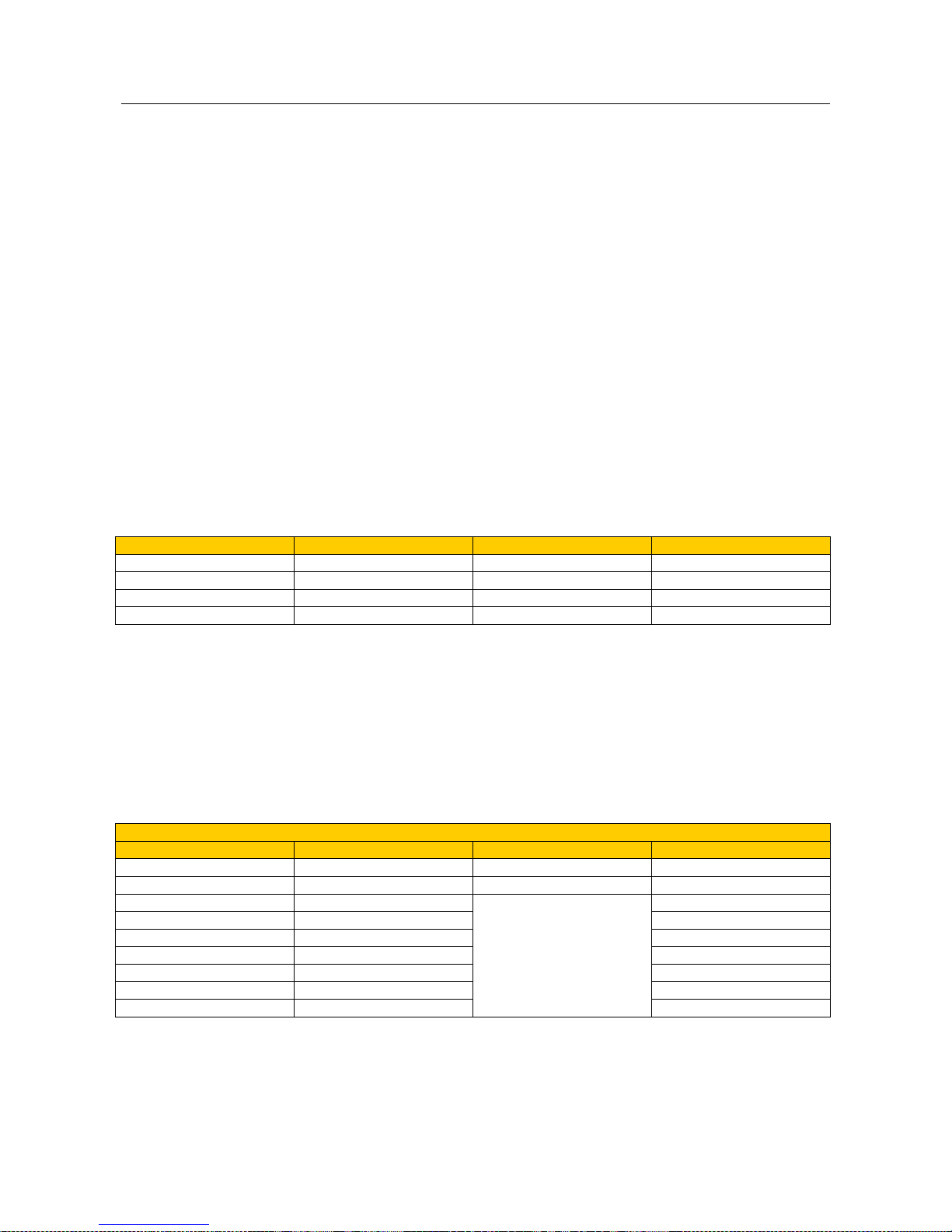
THE MENU
Access the Menu by pressing key 3 (Set).
This is divided into different items and levels that allow access to the board programming and settings.
Scroll through the menus to be changed using keys 5 and 6.
Single menus can be changed using keys 1 and 2.
The menu options allowing access to technical programming (parameters reserved for the Technical
Assistance Centre) are protected by access key.
Listed below is the list of menus available on the board, with various explanations.
1. Menu 01 – Set clock
It sets current date and time.
2. Menu 02 – Set on and off settings
Sub-menu 02 – 01 – enable on and off settings
It allows universal enabling and disabling of all on and off thermostat function settings.
Sub-menu 02 – 02 – daily program
It allows enabling, disabling and setting the daily on and off thermostat function settings.
You can set up two operating ranges bounded by the times set according to the following table where OFF
requires the clock to ignore the command:
MENU LEVEL
SELECTION
MEANING
POSSIBLE VALUES
02 – 02 – 02
START 1
Ignition time
Time – OFF
02 – 02 – 03
STOP 1
Switch-off time
Time – OFF
02 – 02 – 04
START 2
Ignition time
Time – OFF
02 – 02 – 05
STOP 2
Switch-off time
Time – OFF
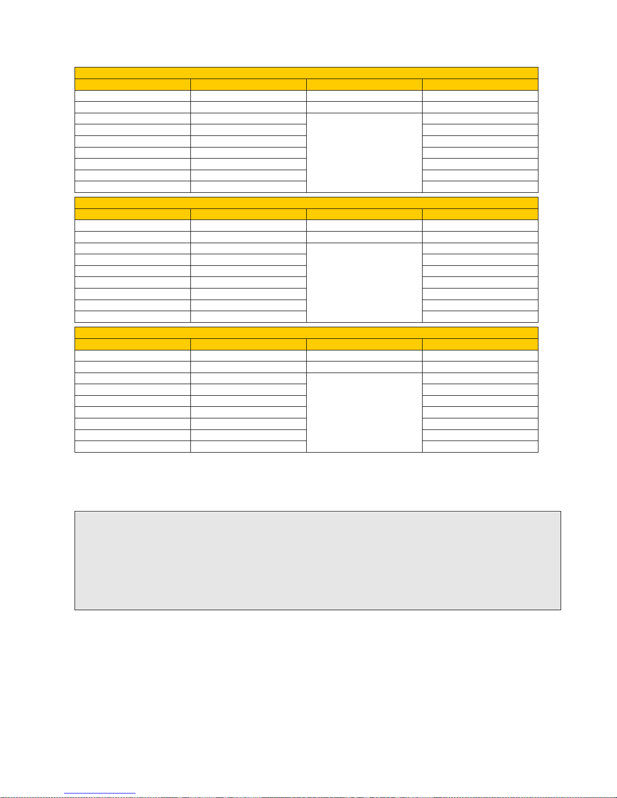
Sub-menu 02 – 03 – weekly program
It allows enabling, disabling and setting the weekly on and off thermostat function settings.
The weekly programmer has 4 independent programs whose impact consists in the combination of the 4
individual programmings.
The weekly programmer can be enabled or disabled.
Furthermore, by setting OFF in the time field, the clock ignores the corresponding command.
PROGRAM 1
MENU LEVEL
SELECTION
MEANING
POSSIBLE VALUES
02 – 03 – 02
START PROG 1
Ignition time
Time – OFF
02 – 03 – 03
STOP PROG 1
Switch-off time
Time – OFF
02 – 03 – 04
MONDAY PROG 1
Days of reference
On/off
02 – 03 – 05
TUESDAY PROG 1
On/off
02 – 03 – 06
WEDNESDAY PROG 1
On/off
02 – 03 – 07
THURSDAY PROG 1
On/off
02 – 03 – 08
FRIDAY PROG 1
On/off
02 – 03 – 09
SATURDAY PROG 1
On/off
02 – 03 – 10
SUNDAY PROG 1
On/off
Page 45
45
PROGRAM 2
MENU LEVEL
SELECTION
MEANING
POSSIBLE VALUES
02 – 03 – 11
START PROG 2
Ignition time
Time – OFF
02 – 03 – 12
STOP PROG 2
Switch-off time
Time – OFF
02 – 03 – 13
MONDAY PROG 2
Days of reference
On/off
02 – 03 – 14
TUESDAY PROG 2
On/off
02 – 03 – 15
WEDNESDAY PROG 2
On/off
02 – 03 – 16
THURSDAY PROG 2
On/off
02 – 03 – 17
FRIDAY PROG 2
On/off
02 – 03 – 18
SATURDAY PROG 2
On/off
02 – 03 – 19
SUNDAY PROG 2
On/off
PROGRAM 3
MENU LEVEL
SELECTION
MEANING
POSSIBLE VALUES
02 – 03 – 20
START PROG 3
Ignition time
Time – OFF
02 – 03 – 21
STOP PROG 3
Switch-off time
Time – OFF
02 – 03 – 22
MONDAY PROG 3
Days of reference
On/off
02 – 03 – 23
TUESDAY PROG 3
On/off
02 – 03 – 24
WEDNESDAY PROG 3
On/off
02 – 03 – 25
THURSDAY PROG 3
On/off
02 – 03 – 26
FRIDAY PROG 3
On/off
02 – 03 – 27
SATURDAY PROG 3
On/off
02 – 03 – 28
SUNDAY PROG 3
On/off
PROGRAM 4
MENU LEVEL
SELECTION
MEANING
POSSIBLE VALUES
02 – 03 – 29
START PROG 4
Ignition time
Time – OFF
02 – 03 – 30
STOP PROG 4
Switch-off time
Time – OFF
02 – 03 – 31
MONDAY PROG 4
Days of reference
On/off
02 – 03 – 32
TUESDAY PROG 4
On/off
02 – 03 – 33
WEDNESDAY PROG 4
On/off
02 – 03 – 34
THURSDAY PROG 4
On/off
02 – 03 – 35
FRIDAY PROG 4
On/off
02 – 03 – 36
SATURDAY PROG 4
On/off
02 – 03 – 37
SUNDAY PROG 4
On/off
Sub-menu 02 – 04 – week-end program
It allows enabling, disabling and setting the week-end (Saturdays and Sundays) on and off
thermostat function settings.
3. Menu 03 – Choose language
It allows selecting the dialogue language among those available (Italian, English, French, German,
and Spanish).
4. Menu 04 – Enable R.T (T.A.) contact (only active if room sensor is enabled on external remote
control)
It enables the Room Thermostat contact operation if the room sensor on the external remote control
is enabled (also see the “Remote control” manual).
The Room Thermostat contact operation is always active if the room sensor on the external remote
control is not enabled.
TIP: To avoid confusion and undesired startup and shutdown operations, turn on only one program at a time if
you do not exactly know what you want to achieve.
If you want to use the weekly program, disable the daily schedule. If you use the weekly program in programs 1,
2,3, and 4, always keep the week-end program disabled.
Only enable week-end programming only after disabling the weekly schedule.
Page 46
46
Example:
In this condition...
...if you want to operate the central heating cooker with KLOVER remote control room temperature only::
enable the room sensor on the remote control (stove settings menu +> Enable room sensor -> ON)
disable the boiler thermostat contact on the central heating cooker display (menu 4 enable contact ->
OFF)
In this case, the central heating cooker first enters economy mode operation, and then automatically
switches off when the desired room temperature (detected with KLOVER remote control) is reached.
...if you want to operate the central heating cooker with KLOVER remote control room temperature and with
boiler thermostat:
enable the room sensor on the remote control (stove settings menu +> Enable room sensor -> ON)
enable the boiler thermostat contact on the central heating cooker display (menu 4 enable contact ->
ON)
In this case, the central heating cooker first enters economy mode operation, and then automatically
switches off when both temperatures have been reached.
...if you want to operate the central heating cooker with the boiler temperature only:
disable the room sensor on the remote control (stove settings menu +> Enable room sensor -> OFF).
The room sensor is automatically disabled if no external remote control is connected.
enable or disable the boiler thermostat contact on the central heating cooker display (menu 4 enable
contact -> ON/OFF)
In this case, the central heating cooker first enters economy mode operation, and then automatically
switches off when the boiler temperature (measured with an external thermostat immersed in the boiler) has
been reached. This may be a viable solution to heat DHW in summer.
...if you do not want to operate the central heating cooker with external thermostats but only with the water
temperature in the heating system:
disable the room sensor on the remote control (stove settings menu +> Enable room sensor -> OFF).
The room sensor is automatically disabled if no external remote control is connected.
enable or disable the boiler thermostat contact on the central heating cooker display (menu 4 enables
contact -> ON/OFF). The contact must obviously be bridged (provided for in the factory).
Only when reaching the temperature set in “SET H2O” or “SET DHW” does the central heating cooker
enter economy mode operation.
Page 47

47
Summary:
CASE
REMOTE CONTROL
ROOM SENSOR
ROOM THERMOSTAT
CONTACT
ACTION
1
OFF
OFF
It works with room thermostat contact
2
OFF
ON
It works with room thermostat contact
3
ON
OFF
It works with remote control room sensor
only
4
ON
ON
It works with remote control room sensor
and room thermostat contact
5. Menu 05 – 3-Way Valve Threshold
It allows setting the temperature threshold for switching the 3-way motorised valve installed in the
DHW system. Change-over occurs after 30" from reaching the set temperature and with a
hysteresis of 2°C.
Example:
3-Way Valve Threshold = 55°C
The valve opens after 30" from reaching 55°C.
The valve closes if 52°C is reached.
6. Menu 06 – Sound alarm
It allows enabling or disabling the sound signal in case of alarm. The sound signal is only available
on the central heating cooker board, and not on the external remote control.
7. Menu 07 – Initial load
It allows pre-loading pellets for 90” with the central heating cooker off and cold. Start the operation
using key 1 and stop it using key 4. It can be useful if the central heating cooker is ignited after fully
emptying the tank, or it is the first time it is filled.
8. Menu 08 – Cooker state
It allows displaying the instantaneous central heating cooker state showing the state of the various
devices connected to it. There are several pages displayed in succession. As the reported data is
reserved for the Technical Assistance Centre, we recommend not accessing this menu.
9. Menu 09 – Technical calibration
It gives access to all that is reserved for the Technical Assistance Centre. Access is protected by an
access key. Unauthorised access can cause serious damage to the equipment and the environment
as well as personal injuries.
Page 48

48
COMMISSIONING
Filling the system for the first time
After connecting the central heating cooker, fill the system as follows:
Check tightness of all piping, the expansion vessel, and the circulation pump;
Open “manual air release valve” of the central heating cooker, located on its left side (see fig. on page
10);
Open the “boiler body and system load cock” (see fig. on page 8) to load the system. Act very slowly to
allow any air to escape from the central heating cooker through the “manual air release valve”;
Optimum working pressure is 1.2 bar;
If necessary, very slowly loosen the pump vent plug draining the fluid for a few seconds;
Vent all radiators and any other deaeration system to ensure that there are no air bubbles.
After installation, check the tightness of all hydraulic joints.
When installation has been completed, it is advised, for the first days of operation, to check the tightness of all
hydraulic joints.
The central heating cooker system can be emptied through the “boiler body and system drain cock” located
inside the “hydraulic compartment” below the cooking oven (see fig. on page 8).
During periods of intense cold it is appropriate that the heating system remains in operation. In
the case of a prolonged absence, antifreeze must be added to the heating water, or the system
be completely emptied.
In a system subject to being emptied frequently, it is essential that filling is performed with water suitably
treated to remove hardness which can give rise to scaling.
Pellet loading and mains connection
Perform the following steps:
Connect the central heating cooker to the electrical system using the cable supplied;
Put the “main ON/OFF switch” (see fig. on page 9) located inside the “technical compartment” of the
central heating cooker in position “׀” (ON);
Fill the pellet tank; for the first start ever, to avoid wasting the time required for filling the entire screw
feed channel (this should be done every time the central heating cooker remains without pellets), we
recommend using what is mentioned in MENU 07 – INITIAL LOAD (see page 46);
Turn on the central heating cooker using the relevant ignition key on the control panel. See the
instructions below.
It is recommended to use high quality pellets so as not to impair the central heating cooker
features. Damage caused by poor pellets is not covered by the warranty.
Central heating cooker ignition cycle
Pressing button 4 (ON/OFF) for a few seconds allows starting the central heating cooker ignition cycle. After a
while, the display shows “START”, and the flue gas intake device and ignition resistance switch on. After 40
seconds, the central heating cooker moves to a pre-load phase ( “PELLET P-LOAD”) useful to quickly fill the
brazier with pellet. The central heating cooker goes into “FLAME STAND-BY” after the pre-load phase.
When the flame is lit, the display shows the message “FIRE”. This step is used to allow the fire to spread
evenly across the brazier. After these steps, the central heating cooker enters work mode at the pre-set
output.
In case of misfire, the central heating cooker goes into “NO IGNIT-” alarm.
The alarm may also occur if the brazier is dirty; in this case, clean the brazier and restart the central
heating cooker.
Page 49

49
Summary:
The ignition cycle can last max 25 minutes and is divided into four steps:
1 - START : Flue gas intake device ignition
duration 40 seconds
2 – PELLET PRE-LOAD : Pellet pre-load (initial continuous load) and resistance ignition
Pr40 = Ignition pre-load time
3 - FLAME STAND-BY : Pellet load (intermittent load) and operation resistance
Pr01 – Pr40 = ignition cycle maximum time – Ignition pre-load time
4 - FIRE PRESENT : Resistance switch-off and flame stabilization
Pr02 = start time
The central heating cooker switches into working mode at the output set during ignition via buttons 1 and 2.
Central heating cooker working mode
During the working phase, by pressing 1, you can set “SET H20” or the water working temperature in the
central heating cooker. When this temperature is reached, the cooker enters the economy mode operation
“T-H2O ECONOMY”.
Before reaching the temperature set on “SET H20”, the central heating cooker starts modulating output by
decreasing the pellet intake and reducing the flue gas suction speed.
Example: “SET H2O” set at 75 °C
Working output set at 5
- Working output automatically changes to 4 when temperature reaches 71°C.
- Working output automatically changes to 3 when temperature reaches 72°C.
- Working output automatically changes to 2 when temperature reaches 73°C.
- Working output automatically changes to 1 when temperature reaches 74°C.
- Working output automatically changes to economy mode operation “T-H2O ECONOMY” when temperature
reaches 75°C.
At this point, the central heating cooker will shut off automatically if at least one of the following conditions
occurs:
If it remains in the economy mode operation “T-H2O ECONOMY” for the time set on Pr44 (30 minute
default setting).
If the temperature differential set on Pr43 (5°C default setting) or H2O Temperature > (“SET H2O” +
Pr43) is exceeded.
The central heating cooker will automatically switch on if:
It goes below the temperature differential set on Pr43 (5°C default setting) or Temperature H2O <
(“SET H2O” – Pr43).
If the above-mentioned condition occurs when the central heating cooker is still carrying out the switch-off
cycle, please wait until it runs out.
The cleaning cycle of the brazier (displayed under “BRAZIER CLEANING”) is done at predetermined time
intervals for an established period (see parameter table).
Page 50
50
Producing domestic hot water (suitable models only)
Domestic hot water is produced instantly via a double heat exchanger immersed in water in the central
heating cooker.
Therefore, to have DHW, the central heating cooker must reach a temperature of at least 60°C.
Set the central heating cooker in DHW output mode “DHW” if a large amount of domestic hot water is
required.
The function of the “DHW” output mode is to postpone the heating pump start-up at higher temperatures, so
as to transfer all the heat produced at these temperatures to domestic hot water.
Press 5 to set the pump starting temperature and use keys 5 or 6 to change the “SET DHW” temperature
(we recommend keeping this temperature at 70–75°C) (also see page 51).
If “DHW” output mode is manually set, the central heating cooker must be reset with working output from 1 to
5 when domestic hot water is no longer required.
The central heating cooker is equipped with a predisposition for the connection to a flow switch that
automatically sets “DHW” output mode when there is demand for hot water. Conversely, when there is more
demand for hot water, the central heating cooker automatically returns to the previously set working output.
Contact the authorised Technical Assistance Centre for the electrical connection of the flow switch.
If water is particularly hard, it is essential to install an anti limescale device at the heat
exchanger inlet, to be chosen according to the water characteristics.
Cooking plate/oven output.
Besides setting one of the five available WORKING OUTPUT VALUE (from 1 to 5) and the DHW OUTPUT,
pressing button 6 also allows selecting one of the three OVEN OUTPUT VALUE (OVEN 1, OVEN 2, OVEN
3) which can only be set when you want to cook. Therefore, press keys 5 and 6 to set the desired output.
During this operation, the display appears as in the figure below.
Set
!
1
2 3 4 5
6
By setting one of the three available OVEN OUTPUT VALUE, the operation of the room thermostat (or of
any other combined thermostat) is excluded. So the central heating cooker will enter modulation mode and
then go off only if the temperature set on SET OVEN is reached (75°C default setting - see parameter
tables).
Re-set one of the five WORKING OUTPUT VALUE (from 1 to 5) when you have finished cooking.
The oven and cooking plate temperatures reached with laboratory tests are shown in the following tables.
OVEN working output 1
MINUTES AFTER IGNITION
OVEN* AVERAGE TEMPERATURE
COOKING PLATE* MAXIMUM
TEMPERATURE
30 MINUTES
120°C
The cooking plate is normally running
after 60 minutes, reaching a
temperature of about 230°C
(temperature measured in the middle
of the plate)
45 MINUTES
165°C
60 MINUTES
190°C
75 MINUTES
200°C
90 MINUTES
205°C
105 MINUTES
205°C
120 MINUTES
210°C
O v e n 2
SET
OUTPUT
Page 51
51
OVEN working output 2
MINUTES AFTER IGNITION
OVEN* AVERAGE TEMPERATURE
COOKING PLATE* MAXIMUM
TEMPERATURE
30 MINUTES
130°C
The cooking plate is normally running
after 60 minutes, reaching a
temperature of about 260°C
(temperature measured in the middle
of the plate)
45 MINUTES
200°C
60 MINUTES
220°C
75 MINUTES
230°C
90 MINUTES
235°C
105 MINUTES
240°C
120 MINUTES
240°C
OVEN working output
MINUTES AFTER IGNITION
OVEN* AVERAGE TEMPERATURE
COOKING PLATE* MAXIMUM
TEMPERATURE
30 MINUTES
150°C
The cooking plate is normally running
after 60 minutes, reaching a
temperature of about 300°C
(temperature measured in the middle
of the plate)
45 MINUTES
230°C
60 MINUTES
260°C
75 MINUTES
270°C
90 MINUTES
270°C
105 MINUTES
275°C
120 MINUTES
280°C
* The temperatures in the tables are approximate and vary depending on the type of pellet burnt and
frequency of cleaning the flue gas turn. The temperature may fall by about 20/30°C if food is put into the oven.
The temperatures were measured starting with the central heating cooker off and cold; the temperatures may
be different from those reported above after several hours of operation.
It is recommended to periodically turn the dripping pan or the cooking grid during cooking to allow a
homogenous baking of the food in the oven.
To cook on a cast iron radiant plate, you should
place the pot on the hottest point of the plate or in
the middle of the circles drawn on it (see figure).
Only use flat bottom pots evenly adhering over the
base.
Central heating cooker switch-off
Pressing button 4 (ON/OFF) the central heating cooker is turned off. The display will show “FINAL
CLEANING”. The pellet load is stopped turning off the motor reducer. The flue gas intake device speed is
increased to maximum and switched off after the equipment cooling, displaying "OFF”.
Page 52
52
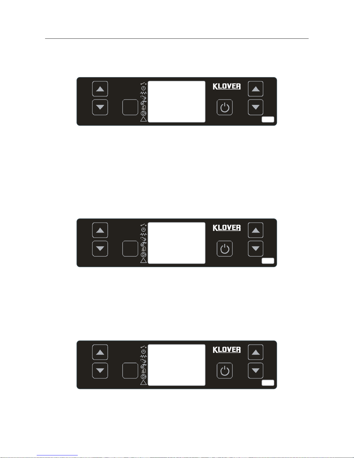
Changing DHW, room, and water temperature settings.
- Water Temperature
Press key 1 and select “SET H2O” to change water temperature. Then press keys 1 and 2. During this
operation, the display appears as shown in the figure below.
Set
!
1
2 3 4 5
6
After setting the desired value, confirm by pressing button 4 or waiting a few seconds. When the set
temperature is reached, the cooker enters economy mode operation. At this point, the cooker will shut off
automatically if at least one of the following conditions occurs:
it remains in economy mode operation “T-H2O ECONOMY” for a time set on Pr44 (30 minute
default setting).
the temperature differential set on Pr43 (factory set value 5°C) or H2O Temperature > (“SET H2O”
+ Pr43) is exceeded.
- Room Temperature
Press key 2 and select “SET ROOM TEMP” to change the room temperature. Then press keys 1 and 2.
During this operation, the display appears as shown in the figure below.
Set
!
1
2 3 4 5
6
Press key 4 or wait a few seconds to confirm the desired value setting.
WARNING: The room thermostat temperature is taken into account if the remote control to be applied to the
wall is connected, (also see page 44 ”Menu 04” ). The room sensor must also be enabled in the remote
control (see the “Remote control” manual).
- DHW Temperature
Press key 5 and select “SET DHW” to change the DHW temperature. Then press keys 5 and 6. During this
operation, the display appears as shown in the figure below.
Set
!
1
2 3 4 5
6
Press key 4 or wait a few seconds to confirm the desired value setting.
70°C
SET
H2O
75°C
SET
DHW
25°C
SET ROOM
TEMPERATUR
Page 53
53
Alarm signals
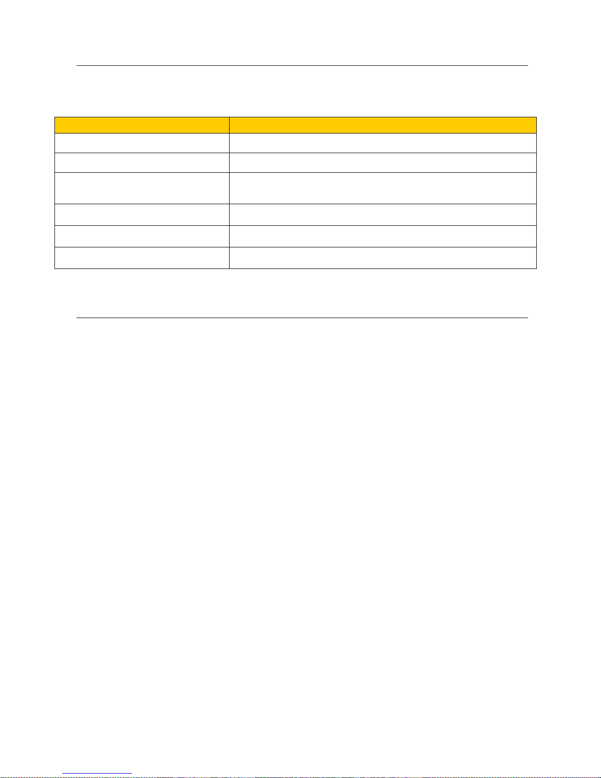
If there is a malfunction in the cooker the display board will activate an alarm and indicate on the display the
type of malfunction that has occurred. The board has the following alarm indications.
DISPLAY
ORIGIN OF ALARM
AL 9
WATER PROBE ACTIVE ALARM
Faulty or disconnected water temperature probe.
AL 2
FLUE GAS PROBE ACTIVE ALARM
Faulty or disconnected flue gas temperature probe.
AL 3
HOT TEMP ACTIVE ALARM
Flue gas over-temperature. When flue gas temperature is higher than 260°C.
Before displaying the alarm, or when flue gas maximum temperature is reached
(Pr14). the display shows “HOT FLUE GAS”.
AL 5
NO IGNIT- ACTIVE ALARM
No ignition. When the flue gas minimum temperature (Pr13) is not reached within
maximum ignition cycle time (Pr01).
AL 6
NO PELLET ACTIVE ALARM
Sudden shutdown during working mode. When, during work, the flue gas
temperature drops below the minimum threshold (Pr13).
AL 4
FAULTY INTAKE DEV- ACTIVE ALARM
Faulty intake device. When the intake device speed measured by an in-built
encoder (tachometer) is equal to 0.
Each alarm condition causes an immediate shutdown.
After the time set on Pr11 (alarms delay) the alarm state is reached; press key 4 to reset it.
What you need to know...
Listed below are some things you should know about the equipment:
It is normal to smell paint from the equipment in the first few days of operation. The first time the
central heating cooker is powered, we recommend keeping the installation room ventilated. We also
recommend setting the cooker at maximum power for the first few days of operation.
The boiler body is treated with an antioxidant paint to protect it against oxidation due to long periods
of disuse. After the first ignition, this paint will no longer have this function, and any wear of the paint
inside the combustion chamber is not to be considered a product defect.
Any perceived noise can be attributed to the boiler body settlement expansion, and is not
considered a manufacturing defect. This noise is primarily perceived during ignition and shutdown.
Page 54

54
WHAT HAPPENS IF..
…the pellet does not ignite
In the event of a misfire, the “NO IGNIT-“ alarm message appears.
Cancel the alarm and reset the central heating cooker to standard condition by pressing key 4 for a
few seconds.
...the fire door is open or closed improperly
If the door is open or closed improperly, the motor reducer cannot be powered electrically thereby
preventing the central heating cooker from being ignited. If the fire door is opened during standard
operation, the central heating cooker will burn all the pellet in the brazier and then activate the “NO
PELLET” alarm (sudden shutdown).
...the flue is dirty, clogged or not properly manufactured
If the flue is dirty, clogged or not properly manufactured, the motor reducer is not electrically
powered and therefore does not turn the cooker on. If the flue becomes clogged during normal
operation, the central heating cooker will burn all the accumulated pellets in the brazier, and then go
into the “NO PELLET” alarm (sudden shutdown).
...the central heating cooker is overheated
If the cooker water is overheated, the motor reducer is not electrically powered and a manual reset
thermostat is enabled. If this happens when the central heating cooker is working, it will go into the
“NO PELLET” alarm (sudden shutdown). It is therefore necessary to reset the thermostat before
restarting the central heating cooker.
...lack of power (black out)
If an outage occurs for a shorter time than Pr48, when power is restored, the central heating cooker
will immediately re-start in the working mode it had been operating with before the outage
(recovering the set working output).
If an outage occurs for a longer time than Pr48, when power is restored, the central heating cooker
will enter the “STOP FIRE” (stand-by) mode running all the switch-off cycle until cooling. When this
phase is over, the cooker can be restarted resuming work at the set output.
Previous state
Black-out
duration
State after power restore
OFF
Any
OFF
START
duration < Pr48
START
START
duration > Pr48
START
P-LOAD PELLET
Any
BLACK OUT ALARM
FLAME STAND-BY
Any
BLACK OUT ALARM
FIRE
duration < Pr48
FIRE
FIRE
duration > Pr48
STOP FIRE with automatic re-ignition after machine cooling
WORK (any phase)
duration < Pr48
WORK (any phase)
WORK (any phase)
duration > Pr48
STOP FIRE with automatic re-ignition after machine cooling
BRAZIER CLEANING
duration < Pr48
BRAZIER CLEANING
BRAZIER CLEANING
duration > Pr48
STOP FIRE with automatic re-ignition after machine cooling
FINAL CLEANING
duration < Pr48
FINAL CLEANING and after cooling OFF
FINAL CLEANING
duration > Pr48
FINAL CLEANING and after cooling OFF
STOP FIRE
Any
STOP FIRE
Page 55
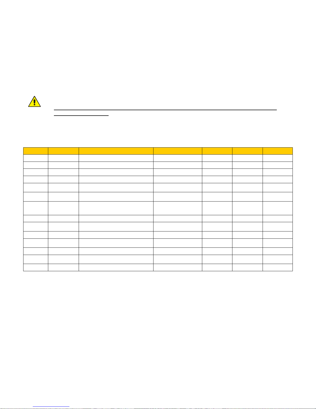
55
CIRCUIT BOARD PARAMETERS
THE PARAMETERS STORED ON THE CIRCUIT BOARD ARE ESSENTIAL FOR THE PROPER
OPERATION OF THE CENTRAL HEATING COOKER.
THE PARAMETERS GIVEN BELOW HAVE ALREADY BEEN STORED DURING THE CENTRAL HEATING
COOKER TESTING PHASE DIRECTLY IN THE FACTORY.
THESE PARAMETERS ARE THE RESULT OF CAREFUL TESTS WITH VARIOUS TYPES OF
PELLETS, AND SHOULD NOT BE CHANGED WITHOUT THE PERMISSION OF KLOVER srl SO AS
NOT TO IMPAIR THE CENTRAL HEATING COOKER OPERATION.
THE MANUFACTURER DISCLAIMS ALL LIABILITY FOR ANY DAMAGE CAUSED BY IMPROPER
PARAMETER ENTRIES.
“Various calibrations” (Menu M – 9 – 4)
Parameter
Menu level
Description
Display writing
Measurement
Value field
Database o0
Pr38
M – 9 – 4 – 01
Re-ignition block
RE-IGNIT BLOCK
Minutes
0 – 10
6
Pr39
M – 9 – 4 – 02
Flue gas intake device switch-off time
MIN-INT OFF
Minutes
0 – 20
10
Pr40
M – 9 – 4 – 03
Ignition pre-load time
IGNIT- PRE-LOAD
Seconds
0 – 225
85
Pr41
M – 9 – 4 – 04
Stand-by time after pre-load
AFTER-PRE STAND-BY
Seconds
0 – 255
210
Pr42
M – 9 – 4 – 05
Intake device speed in pre-load phase
PRELOAD FLUE GASINTAKE DEVICE
Revs/min
350 – 2800
2100
Pr43
M – 9 – 4 – 06
ON/OFF Temperature hysteresis on
“SET H2O” and “SET DHW”
DELTA ON OFF AUTO
°C
0 – 20
5
Pr44
M – 9 – 4 – 07
Delay at economy operation mode
switch-off (timer after reaching “SET
H2O”)
DELAY-OFF AUTO
Minutes
2 – 120
30
Pr45
M – 9 – 4 – 08
Power change delay
POWER CHANGE
Seconds
0 – 60
20
Pr46
M – 9 – 4 – 09
ON/OFF Temperature hysteresis on
“SET ROOM”
DELTA ON AUTO
°C
0 – 15
2
Pr47
M – 9 – 4 – 10
Keypad block enabling
KEYS BLOCK-EN
On – off
On – off
Off
Pr48
M – 9 – 4 – 11
Automatic re-ignition after black-out
BLACK OUT REIGNITION
Seconds
0 – 60
30
Pr49
M – 9 – 4 – 12
Pellet level sensor enabling
PELLET RESERVE
On – off
On – off
On
Pr50
M – 9 – 4 – 13
Pump ignition for over-temperature
safety
PUMP SAFETY
°C
60 - 90
83
Pr51
M – 9 – 4 – 14
“SET OVEN” Temperature
SET OVEN
°C
70 - 80
75
Page 56

56
“Default settings” (Menu M – 9 – 6)
Parameter
Menu level
Description
Display writing
Measurement
Value field
Database o0
Pr01
M – 9 – 6 – 01
Ignition cycle maximum time
IGNIT- MINUTES
Minutes
5 – 25
25
Pr02
M – 9 – 6 – 02
Start time
START MINUTES
Minutes
2 – 12
5
Pr03
M – 9 – 6 – 03
Time interval between the two brazier
cleaning operations
BRAZIER CLEANING
Minutes
3 – 240
60
Pr04
M – 9 – 6 – 04
Screw feed motor reducer ON time in
ignition phase
IGNIT- SCREW FEED
Seconds
0.1 – 8.0
2,2
Pr05
M – 9 – 6 – 05
Screw feed motor reducer ON time in start
phase
START SCREW FEED
Seconds
0.1 – 8.0
2,0
Pr06
M – 9 – 6 – 06
Screw feed motor reducer ON time in
output 1 working mode
OUTPUT 1 SCREW
FEED
Seconds
0.1 – 8.0
1,8
Pr07
M – 9 – 6 – 07
Screw feed motor reducer ON time in
output 2 working mode
OUTPUT 2 SCREW
FEED
Seconds
0.1 – 8.0
2,8
Pr08
M – 9 – 6 – 08
Screw feed motor reducer ON time in
output 3 working mode – Oven output 1
OUTPUT 3 SCREW
FEED
Seconds
0.1 – 8.0
4,2
Pr09
M – 9 – 6 – 09
Screw feed motor reducer ON time in
output 4 working mode – Oven output 2
OUTPUT 4 SCREW
FEED
Seconds
0.1 – 8.0
5,4
Pr10
M – 9 – 6 – 10
Screw feed motor reducer ON time in
output 5 working mode – Oven output 3
OUTPUT 5 SCREW
FEED
Seconds
0.1 – 8.0
6,8
Pr11
M – 9 – 6 – 11
Alarm delay
ALARM DELAY
Seconds
20 – 90
30
Pr12
M – 9 – 6 – 12
Brazier cleaning duration
BRAZIER CLEANING
Seconds
0 – 120
40
Pr13
M – 9 – 6 – 13
Flue gas minimum temperature to
consider the boiler on
MINIMUM
THRESHOLD
°C
40 – 180
50
Pr14
M – 9 – 6 – 14
Flue gas maximum temperature
MAXIMUM
THRESHOLD
°C
110 – 250
250
Pr15
M – 9 – 6 – 15
Flue gas temperature threshold for the
exchanger ignition (NOT USED)
FAN THRESHOLD
°C
50 – 210
60
Pr16
M – 9 – 6 – 16
Flue gas intake device speed in ignition
phase
IGNIT FLUE GAS
SPEED
Revs/min
500 – 2800
2100
Pr17
M – 9 – 6 – 17
Flue gas intake device speed in start
phase
START FLUE GAS
SPEED
Revs/min
500 – 2800
2200
Pr18
M – 9 – 6 – 18
Flue gas intake speed in output 1 working
mode
P 1 FLUE GAS
SPEED
Revs/min
500 – 2800
1600
Pr19
M – 9 – 6 – 19
Flue gas intake speed in output 2 working
mode
P 2 FLUE GAS
SPEED
Revs/min
500 – 2800
1750
Pr20
M – 9 – 6 – 20
Flue gas intake speed in output 3 working
mode – Oven output 1
P 3 FLUE GAS
SPEED
Revs/min
500 – 2800
1900
Pr21
M – 9 – 6 – 21
Flue gas intake speed in output 4 working
mode – Oven output 2
P 4 FLUE GAS
SPEED
Revs/min
500 – 2800
2100
Pr22
M – 9 – 6 – 22
Flue gas intake speed in output 5 working
mode – Oven output 3
P 5 FLUE GAS
SPEED
Revs/min
500 – 2800
2250
Pr23
M – 9 – 6 – 23
Exchanger 1 motor speed in output 1
working mode (NOT USED)
AIR 1 SPEED
Volt
65 – 225
65
Pr24
M – 9 – 6 – 24
Exchanger 1 motor speed in output 2
working mode (NOT USED)
AIR 2 SPEED
Volt
65 – 225
65
Pr25
M – 9 – 6 – 25
Exchanger 1 motor speed in output 3
working mode (NOT USED)
AIR 3 SPEED
Volt
65 – 225
65
Pr26
M – 9 – 6 – 26
Exchanger 1 motor speed in output 4
working mode (NOT USED)
AIR 4 SPEED
Volt
65 – 225
65
Pr27
M – 9 – 6 – 27
Exchanger 1 motor speed in output 5
working mode (NOT USED)
AIR 5 SPEED
Volt
65 – 225
65
Pr28
M – 9 – 6 – 28
Flue gas intake device switch-off
threshold (in switch-off phase)
THRESHOLD OFF
°C
50 – 180
70
Pr29
M – 9 – 6 – 29
Flue gas intake device speed in brazier
cleaning phase
FLUE GAS-INTAKE
DEVICE CLEANING
Revs/min
500 – 2800
2800
Pr30
M – 9 – 6 – 30
Screw feed motor reducer ON time in
cleaning phase
CLEANING SCREW
FEED
Seconds
0.1 – 8.0
1,5
Pr31
M – 9 – 6 – 31
Flue gas intake device encoder enabling
(NOT USED)
ENCODER
On – off
On – off
On
Pr32
M – 9 – 6 – 32
Screw feed brake time
BRAKE TIME
Seconds
0 – 0.5
0,2
Pr33
M – 9 – 6 – 33
Pump activation threshold
PUMP THRESHOLD
°C
20 – 70
55
Pr34
M – 9 – 6 – 34
Water pressure switch enabling (NOT
USED)
WATER
PRESSURESW.
On – off
On – off
Off
Pr35
M – 9 – 6 – 35
Water pressure threshold (NOT USED)
PRESSURE
THRESHOLD
Bar
1.5 – 3.0
2,5
Pr36
M – 9 – 6 – 36
Screw feed motor reducer ON time in
DHW output working mode
DHW SCREW FEED
Seconds
0.1 – 8.0
6,8
Pr37
M – 9 – 6 – 37
Flue gas intake speed in DHW output
working mode
DHW FLUE GASINTAKE DEVICE
Revs/min
500 – 2800
2250
Page 57
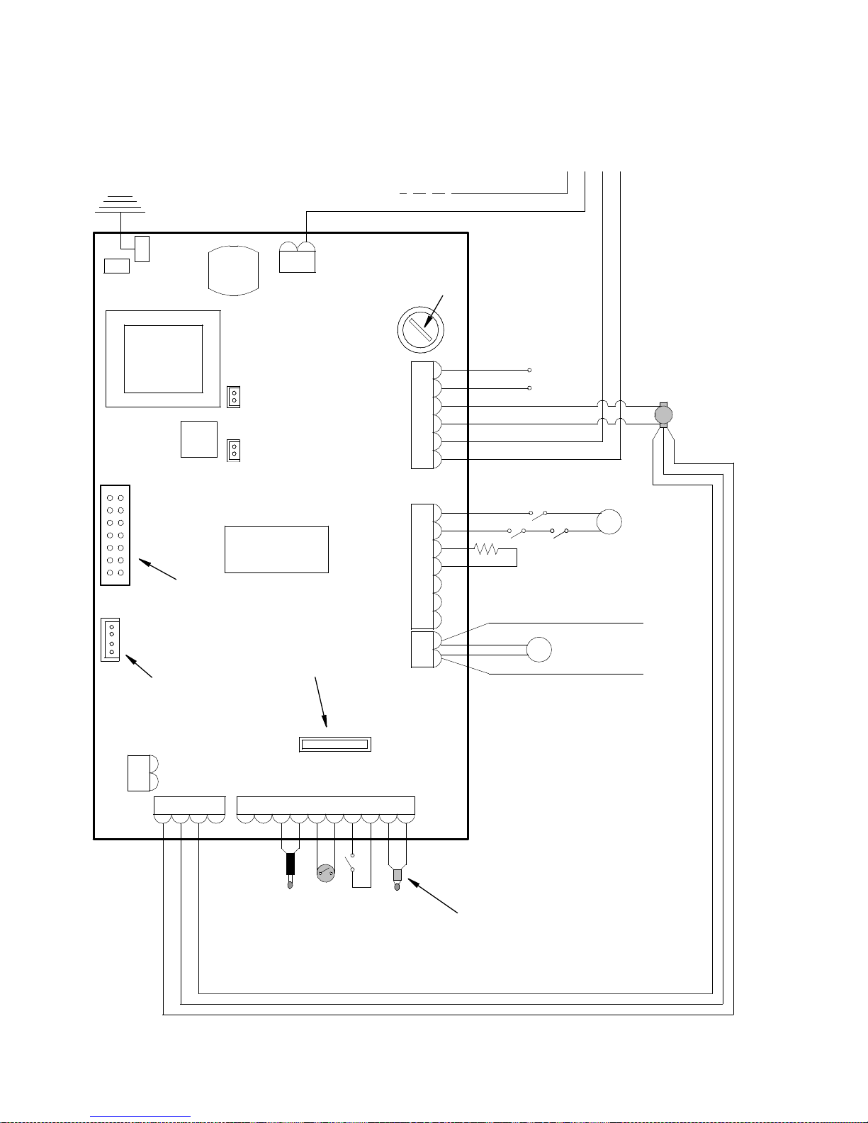
57
WIRING DIAGRAM
TRANSFORMER
IGNITION RELAY
EARTH
FLUE GAS
EXTRATION
INTAKE DEVICE
PHASE
NEUTRAL
230Vac
NETWORK
BROWN
BLUE
M
SCREW FEED
MOTOR REDUCER
ALF
ALP
IGNITION
RESISTANCE
ROOM
THERMOSTAT
CN4
CN8
CN9
CN13
CN5
CN1
CN2
CN7
PELLET SIDE
FUMES PROBE
N.PEL.
N.H20
N.AMB.
TERM.
BLUE
RED
WATER
PROBE
-TC1+
ACC.
COC.
N
F
SCAM.
FUMI
N
AL1AL2
IMPORTANT: DO NOT
INVERT THE POSITI ON
OF THE W IRES
CN6
DISSIPATER
N
F
SCAM
FUMI
CN15
FUSE
4A 5X20
CN12
CN10
BOARD I023
CN14
DISPLA Y
CONNECTO R
WIRES (WITH 220V)
CONTROL OF ANT
COUPLED BOILER
SCAM.
AUX
ALT
P
HEATING SYSTEM
PUMP
CONNECTOR
FOR SERIAL OR
EXPANSION BOARD
I055 CONNECTION
CR2032 3Volts
CHRONO-THERMOSTAT
CLOCK BATTERY
BROWN ON CABLE
BLACK ON CABLE
BLUE ON CABLE
GREEN/YELLOW EARTH ON CABLE
4 x 0,75 CABLE (O PTIONAL)
FOR CONNECT ION OF THE
MOTORISE D 3-WAY VALVE
DHW FLOW
SWITCH
(optional)
TACHOMETER CONNECTION WIRES
BLACK
WHITE
RED
SAFETY DEVICES KEY:
ALP = DOOR CLOSING MICRO SWITCH
ALF = FLUE GAS PRESSURE SWITCH
ALT = MANUAL RE-ARM THERMOSTAT
CONNECT A RELAY AT SET-UP WIRES
OUTLET (POWERED WITH 220V VOLTAGE)
FOR ELECTRIC CONNECTION TO
COUPLED BOILER.
THREE-WAY CONNECTION KEY:
BLUE = COMMON
BLACK = PHASE OPENING
BROWN = PHASE CLOSING
YELLOW/GREEN = EARTH MASS
Page 58

58
WARRANTY
CERTIFICATE
- The warranty period starts from the date of purchase of the product, which must be proved by a
delivery document or other document issued by the selling firm. The document must be submitted to
the Technical Assistance Centre, if required.
- A copy of the warranty coupon (commissioning report) issued by the KLOVER Technical
Assistance Centre must be preserved along with the proof of purchase receipt.
- KLOVER s.r.l. disclaims any liability for accidents resulting from failure to comply with the
specifications contained the use and maintenance manual attached to the equipment.
- Furthermore, KLOVER s.r.l. declines any liability arising from misuse of the product by the user,
unauthorized modifications and/or repairs, as well as use of non-original spare parts or not suitable
parts for this type of product.
KLOVER s.r.l. guarantees the quality of materials, good construction, and functionality
of the product for a period of 2 years, under the following conditions:
1. Any product which in its sole discretion, is deemed defective in materials or workmanship will be
repaired or replaced; with the exclusion of all costs for transport, recovery (hydraulic, disassembly
and assembly operations, building work, and any other required operation), and auxiliary
materials;
2. The warranty does not cover:
- Ceramic glass coatings and ceramic-tiled and/or painted steel coverings as they can be
damaged accidentally being very vulnerable to impact;
- any ceramic-tiled part showing colour shade variations, pin holing, cracks, shading and slight
variations in size, because they cannot be considered product defects but rather characteristics
craftsmanship characteristics.
- the cast iron pellet burner, the cast iron grid and cooking plate, the smoke deflector, the flame
arresters, gaskets, fuses or batteries making up the electronic equipment, and any other
removable component, where it cannot be proved it is a manufacturing defect and not normal
wear.
- Electrical and electronic parts whose failure can be related to a non-standard electrical
connection, natural disasters (lightning, electric discharges, etc.), and variation other than the
rated voltage.
- Any parameter calibration due to the fuel type or the type of installation of the equipment.
3. Replaced parts are warranted for the remaining warranty period from the date of purchase and/or
for a period not exceeding 6 months;
4. The use of poor quality pellets, wood or other fuel could damage the equipment parts making the
warranty void and exempting the manufacturer from any liability. Therefore, we recommend using
fuel as per our specifications;
5. Improper installation by unqualified personnel, tampering with, and failure to comply with the rules
contained in this "use and maintenance manual", and those regarding “workmanlike installation”
will void any warranty claim; the same applies to any damage caused by external factors. In all
cases, direct or indirect damage is not covered by the warranty, whatever the nature or the cause
thereof;
6. Please note that the goods travel under the customer’s responsibility, even if delivered carriage
free, therefore we are relieved of all liability for any damage caused by loading and unloading,
accidental blows, storage in unsuitable places, etc;
7. The boiler unit of only water-based products connected to a heating and/or domestic hot water
system is guaranteed for 5 years, at the above-mentioned conditions.
8. The warranty is accepted only if the warranty coupon (commissioning report) is completed and
legible in all its parts by the authorized Technical Assistance Centre. For the validity of the
warranty, equipment commissioning must only be carried out by the authorized Technical
Assistance Centre within 3 months from date of purchase and no later than 30 days from date of
installation.
For all disputes, Verona is deemed to be the exclusive competent court of law.
Page 59

59
Page 60

PELLET, WOOD and PELLET/WOOD FIRED
THERMAL FIREPLACES - CENTRAL HEATING COOKERS –
THERMAL STOVES - BOILERS
Via A. Volta, 8 – 37047 San Bonifacio (VR) Italy
Tel. 045 6101859 – Fax 045 6101858
S.R.L.
 Loading...