

Page 1
ENGLISH
Wood burning
boiler cooker
ALTEA 110
SICURO TOP
INSTALLATION, USE, MAINTENANCE
AND HELPFUL TIPS
Page 2

Page 3
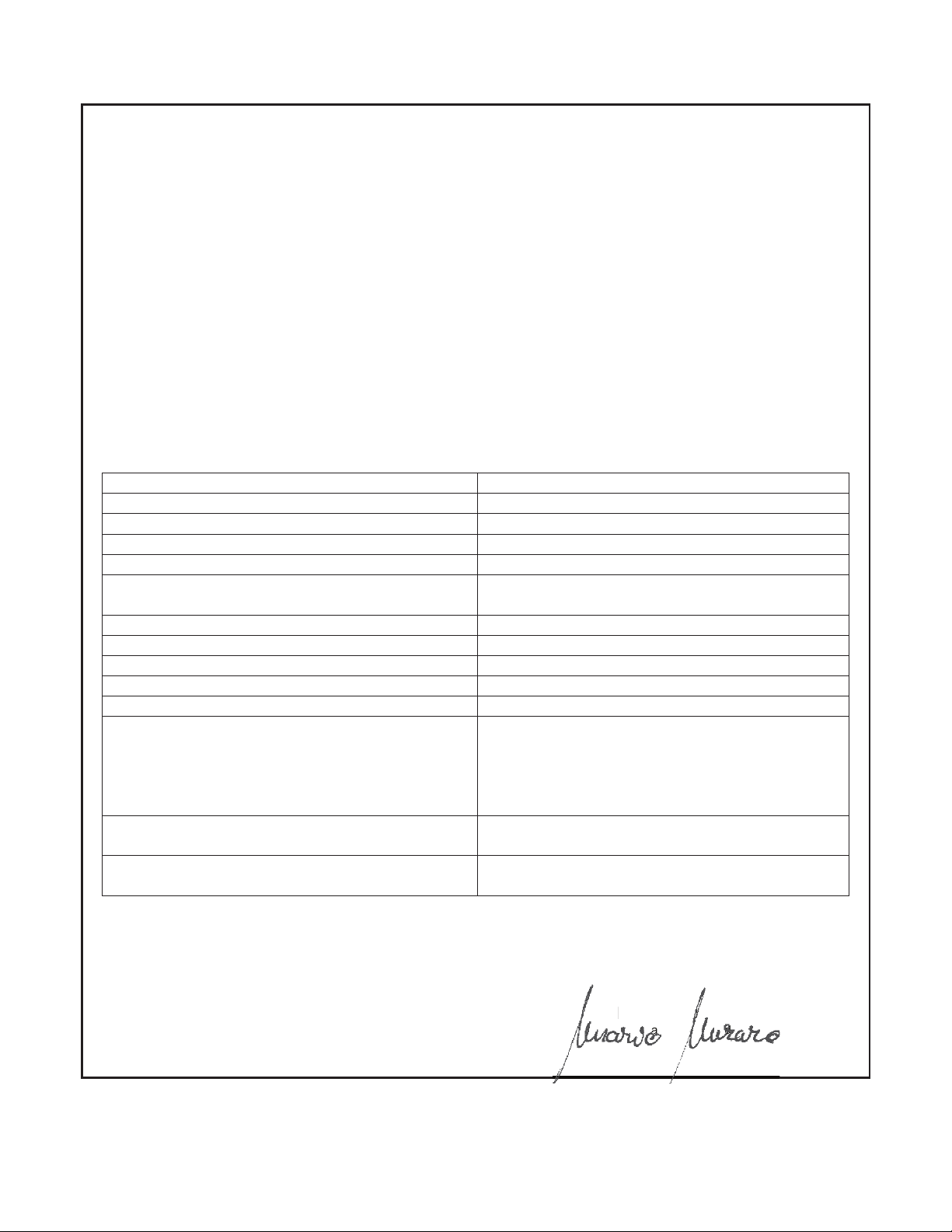
SERVICE DECLARATION
Ref. Annex III EU Regulation no. 305/2011
DoP/KLOVER-029
1. Identification number
:
ALT110TOP / ALT110TOP-P
2. Model and/or lot no. and/or serial no. (Art.11-4)
:
ALTEA 110
3. Intended use of the product according to the relevant
harmonised technical specification
:
Home heating appliance fuelled by wood pellets,
which can also produce domestic hot water
4. Name or trademark of the manufacturer (Art11-5)
:
KLOVER s.r.l.
I - 37047 San Bonifacio (VR) – Via A. Volta, 8
5. Name and address of the representative (Art.12-2)
:
-
6. Assessment and verification system of the
performance constancy (Annex 5)
:
System 3
7. Notified laboratory
:
NB 1880
ACTECO s.r.l.
I - 33084 Cordenons (PN) – Via Amman, 41
Number of test report (based on System 3)
:
1880-CPR-031-16
8. Declared performances
HARMONISED TECHNICAL SPECIFICATION
EN 13240:2006
PERFORMANCE FEATURES
PERFORMANCE
Fire resistance
A1
Distance from combustible material
200 mm
Fuel spillage risk
Compliant
Emission of combustion products
- Nominal power
CO at 13% of O2 0.091 %
Effective temperature Compliant
Electrical safety
Compliant
Accessibility and cleaning Compliant
Maximum operating pressure
2.5 bar
Mechanical strength
NPD (performance not determined)
Thermal performance
-
Nominal power
-
Nominal heat output transmitted to the
environment
- Nominal heat output transmitted to water
14.7 kW
6.5 kW
8.2 kW
Yield
- Nominal power
ɳ 87.7 %
Flue gas temperature
- Nominal power
T 138 °C
9. The performance of the product referred to in points 1 and 2 is compliant with the declared performance in
point 8.
This declaration is released on the sole responsibility of the manufacturer referred to in point 4.
Signed in the name and on behalf of the manufacturer by:
San Bonifacio (VR), 26/09/2016
Mario Muraro
Chairman of the Board
Mu
ro
an
an
of
the
ardard
ard
Page 4

1
CONTENTS
CONTENTS .............................................................................................................................................................................................1
INTRODUCTION .....................................................................................................................................................................................3
IMPORTANT SAFETY INSTRUCTIONS ........................................................................................................................................................3
THE APPLIANCE AND WOOD ..............................................................................................................................................................4
COMPONENTS OF THE APPLIANCE ..........................................................................................................................................................4
OVERALL DIMENSIONS ...........................................................................................................................................................................8
CONNECTIONS DATA SHEET ...................................................................................................................................................................9
TECHNICAL SPECIFICATIONS ...............................................................................................................................................................10
TYPES OF WOOD .................................................................................................................................................................................10
REQUIREMENTS OF THE PLACE OF INSTALLATION .....................................................................................................................12
POSITIONING ......................................................................................................................................................................................12
EXTERNAL AIR INTAKE .........................................................................................................................................................................12
THE FLUE AND CONNECTION TO THE SAME ............................................................................................................................................13
CHIMNEY ............................................................................................................................................................................................13
ELECTRICAL CONNECTION ...............................................................................................................................................................14
ELECTRONIC CONTROL UNIT ................................................................................................................................................................14
CONTROL OF ANY COUPLED BOILER .....................................................................................................................................................19
CONTROL OF A POSSIBLE THREE-WAY MOTORISED VALVE FOR THE DHW SYSTEM (ON APPLICABLE MODELS ONLY) ...................................19
EXAMPLE OF ELECTRICAL CONNECTION ................................................................................................................................................20
HYDRAULIC CONNECTION ................................................................................................................................................................21
INITIAL START-UP ...............................................................................................................................................................................23
FILLING THE BOILER UNIT AND THE SYSTEM FOR THE FIRST TIME ............................................................................................................23
ANTIFREEZE PROTECTION ...................................................................................................................................................................24
SWITCHING ON ...................................................................................................................................................................................24
OPERATION ........................................................................................................................................................................................25
THE OVEN AND THE COOKING HOTPLATE ..............................................................................................................................................25
PRODUCTION OF DOMESTIC HOT WATER (SUITABLE MODELS ONLY) ........................................................................................................26
BOILING .............................................................................................................................................................................................27
PROBLEMS, ALARMS, USEFUL ADVICES ........................................................................................................................................27
USEFUL INFO… ..................................................................................................................................................................................27
WHAT HAPPENS IF THERE IS.. ..............................................................................................................................................................28
CLEANING AND MAINTENANCE........................................................................................................................................................29
PRECAUTIONS BEFORE CLEANING ........................................................................................................................................................29
CLEANING THE COMBUSTION CHAMBER ................................................................................................................................................29
CLEANING THE ASH DRAWER ...............................................................................................................................................................32
CLEANING THE CERAMIC GLASS ...........................................................................................................................................................32
CLEANING THE COOKING HOTPLATE .....................................................................................................................................................32
CLEANING THE FLUE ...........................................................................................................................................................................33
MAINTENANCE ....................................................................................................................................................................................33
MAINTENANCE OF THE BOILER UNIT ......................................................................................................................................................33
WARRANTY CONDITIONS ..................................................................................................................................................................35
Page 5

WOOD BURNING BOILER COOKER ALTEA 110 SICURO TOP
2
EN - Rev. 1.2
Dear client,
First of all we would like to thank you for choosing a “KLOVER” product and we hope you will be satisfied with this
product.
Read the warranty guarantee carefully, which is found on the last page of this User guide; fill out the attached warranty
card in full and return it within 10 days from the date of purchase.
We would like to thank you again for trusting KLOVER products, and we would also like inform you that these models
are the result of forty years of experience in the manufacture of solid fuel products using water as heat transfer fluid.
Every single detail of the product is manufactured by qualified staff, using the most advanced equipment.
The manual contains a detailed description of the appliance and its operation, instructions for proper installation, basic
maintenance and control points, which must be periodically performed; furthermore it contains practical advice which
helps to obtain maximum performance from the appliance with minimum fuel consumption.
Stay warm with KLOVER!
Copyright
All rights reserved. The reproduction of any part of this manual, in any form, without the explicit written permission of
KLOVER Srl. is forbidden. The content of this manual may be modified without notice. Although the documentation
contained in this manual has been carefully compiled and checked, KLOVER srl cannot be held liable for any damages
arising from the use of the same.
Copyright © 2016 KLOVER srl
Page 6

WOOD BURNING BOILER COOKER ALTEA 110 SICURO TOP
3
EN - Rev. 1.2
INTRODUCTION
Important safety instructions
Please read these instructions before installing and using the appliance.
- The installation and initial start-up of the appliance must be performed by skilled personnel trained in the relevant
safety standards. They will be responsible for the definitive installation of the appliance and its proper operation.
KLOVER srl shall not be held liable if these precautions are not observed.
- During installation of the appliance, all local regulations - including those referring to national and European
Standards - must be observed.
- Connect the flue gas outlet to a flue with the specifications described in the “Flue and its connection” section of this
User guide.
- The appliance is not suitable for installation on a shared flue system.
- If the flue should catch fire, use appropriate fire extinguishing equipment or call the fire brigade.
- Connect the appliance to an earthed power socket. Avoid using sockets controlled by switches or automatic timers.
- Do not use the power supply cable if damaged or worn.
- If a multiple socket is used, make sure that the total voltage of the connected devices does not exceed the rated
voltage for the socket. Also make sure that the total voltage of all the devices connected to the socket does not
exceed the maximum permitted level.
- Do not use flammable substances to clean the appliance or its parts.
- Do not leave flammable containers and substances in the place where the appliance is installed.
- The appliance works exclusively with logs and only with the hearth door shut.
- NEVER open the door of the appliance during normal operation.
- The use of poor quality wood or any other material can damage the appliance operation, voiding the warranty and
exempting the manufacturer from all liability.
- Do not use the appliance as an incinerator or for any use other than that for which it was designed.
- Do not use fuels other than those recommended.
- Do not use liquid fuels.
- The appliance, and its outer surfaces in particular, become very hot to the touch during operation; handle with
caution in order to avoid burns.
- Use the anti-burn glove to open the fire door and to regulate the smoke dampers and combustion air.
- Only use original spare parts recommended by the manufacturer.
- Do not make any unauthorised modifications to the appliance.
- Do not touch the hot components of the appliance (ceramic glass, flue and the entire outer frame) during normal
operation.
- Never touch the appliance if you are barefoot and/or if you have wet or damp parts of the body.
- Use the appropriate button to switch off the electrical panel. Do not disconnect the power supply cable while the
appliance is operating.
- During the ignition phase and normal operation of the appliance, maintain the necessary safety distance and do not
remain standing in front of it.
- Keep children away from the appliance when it is running since they could get burned by touching its hot
components.
- Do not leave the packaging elements within reach of children or unassisted disabled persons.
- Children and inexperienced people must not be allowed to use the appliance.
- Do not use the appliance in ways other than those indicated in this user guide.
- The appliance is designed for indoor use only.
- This user guide constitutes an integral part of the appliance. If the appliance is sold to another user, this manual must
be passed on to the new owner.
KLOVER S.R.L. DECLINES ALL LIABILITY IN CASE OF ACCIDENTS DUE TO FAILURE TO COMPLY WITH THE
SPECIFICATIONS OF THIS MANUAL.
KLOVER S.R.L. DECLINES ALL LIABILITY DUE TO INCORRECT USE OF THE APPLIANCE BY THE USER,
UNAUTHORISED MODIFICATION AND/OR REPAIRS, AND USE OF NON-ORIGINAL SPARE PARTS OR SPARE
PARTS NOT SPECIFICALLY DESIGNED FOR USE ON THIS APPLIANCE MODEL.
Page 7

WOOD BURNING BOILER COOKER ALTEA 110 SICURO TOP
4
EN - Rev. 1.2
KLOVER S.R.L. SHALL NOT BE HELD LIABLE FOR THE INSTALLATION OF THE APPLIANCE. THE INSTALLER
IS THE SOLE PARTY RESPONSIBLE FOR THIS OPERATION AND IS ALSO ENTRUSTED WITH CHECKING THE
FLUE, EXTERNAL AIR VENT AND THE CORRECTNESS OF THE PROPOSED INSTALLATION SOLUTIONS. ALL
THE SAFETY REGULATIONS SET OUT IN THE SPECIFIC LAWS IN FORCE IN THE COUNTRY WHERE THE
MACHINE IS INSTALLED MUST BE OBSERVED.
NON-ROUTINE MAINTENANCE MUST ONLY BE PERFORMED BY AUTHORISED AND QUALIFIED STAFF.
To ensure the validity of the warranty, the user must comply with the instructions contained in this guide and, in
particular, must:
- Use the appliance within its operating limits;
- Regularly perform all maintenance activities;
- Authorise expert and competent people to use the appliance.
Failure to comply with the instructions contained in this guide shall automatically void the warranty.
THE APPLIANCE AND WOOD
Components of the appliance
The table below shows the standard features of the appliance:
Expansion tank
6 l
Safety valve
2.5 bar
Pressure gauge
0 – 4 bar
Check valve
Yes
Automatic air vent valve
Yes
Heating system pump
Yes. Mod.25/70
Heating exchanger
Yes
DHW heat exchanger
On prepared models only
System loading cock
Yes
Boiler unit loading cock
Yes
The appliance is delivered with the following equipment:
- No. 1 user, installation and maintenance guide;
- No. 1 allen key 5 mm;
- No. 1 fireside poker;
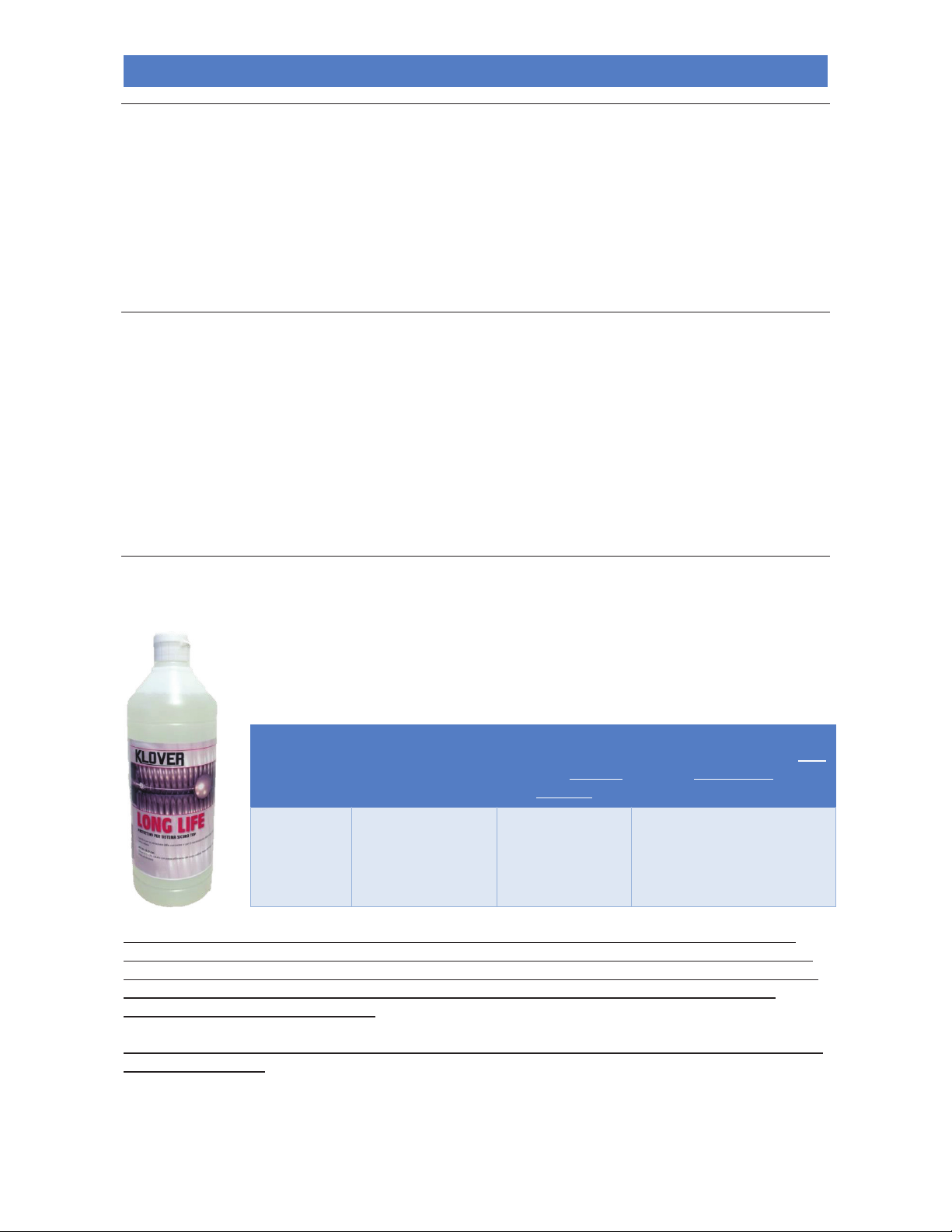
- No. 1 bottle 1 l “LONG LIFE” protective.
Page 8
WOOD BURNING BOILER COOKER ALTEA 110 SICURO TOP
5
EN - Rev. 1.2
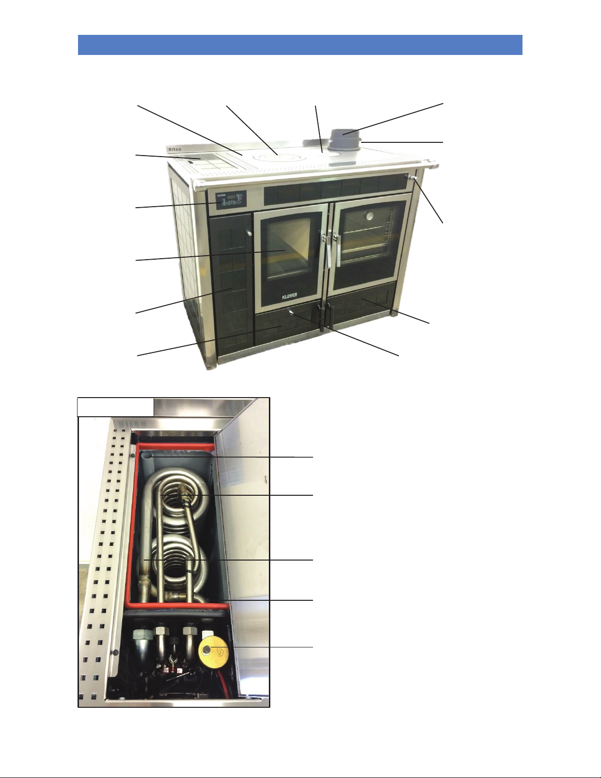
Draught regulation
handle.
Turn the handle to the
vertical position to open.
Turn the handle to the
horizontal position to close.
Primary manual combustion air
damper.
Move the knob to the right to open “+
”.
Move the knob to the left to close “-”.
Left side
technical
compartment.
Combustion
chamber.
SICURO TOP
cover.
Electronic
control
unit.
Internal smoke stream
damper knob.
Pull the knob out to open.
Push the knob in to close.
Right side technical
compartment.
Ash collection
drawer
compartment.
SICURO TOP
Primary
hotplate.
Secondary
hotplate.
Primary exchanger
(heating).
Secondary exchanger (domestic)
(on prepared models only).
Automatic air vent valve. (jolli)
Level switch
(water level sensor).
Boiling discharge pipe SICURO TOP.
Upper smoker damper.
Cooking
hotplate.
Page 9

WOOD BURNING BOILER COOKER ALTEA 110 SICURO TOP
6
EN - Rev. 1.2
FRONT VIEW of LEFT-SIDE TECHNICAL
COMPARTMENT
FRONT VIEW of RIGHT-SIDE TECHNICAL COMPARTMENT
Boiler unit loading cock.
High-efficiency circulating
pump for heating system.
Circulating pump speed switch.
Pressure gauge
(indicates the
pressure of the
heating system).
Boiler unit drain
cock.
Grate raising lever.
Expansion tank
6 l with pre-load 1 bar.
System drain cock.
Heating system loading
cock.
Secondary automatic combustion air damper.
Turn the knob anti-clockwise to open.
Turn the knob clockwise to close.
Page 10
WOOD BURNING BOILER COOKER ALTEA 110 SICURO TOP
7
EN - Rev. 1.2
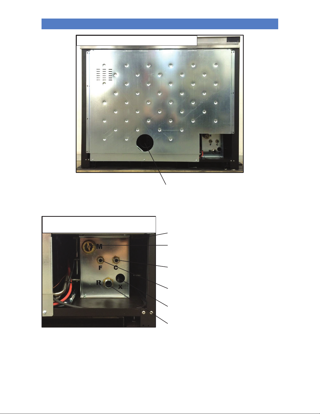
Return pipe connection of the heating system.
REAR VIEW OF PLUMBING CONNECTIONS
Air intake pipe.
Delivery pipe connection of the heating
system with check valve.
Domestic hot water outlet pipe connection
(on prepared models only).
DCW inlet pipe connection.
+ System load.
+ Boiler unit load.
Safety valve drain connection.
REAR VIEW of LEFT-SIDE TECHNICAL
COMPARTMENT
Boiling discharge pipe connection SICURO TOP.
Page 11
WOOD BURNING BOILER COOKER ALTEA 110 SICURO TOP
8
EN - Rev. 1.2
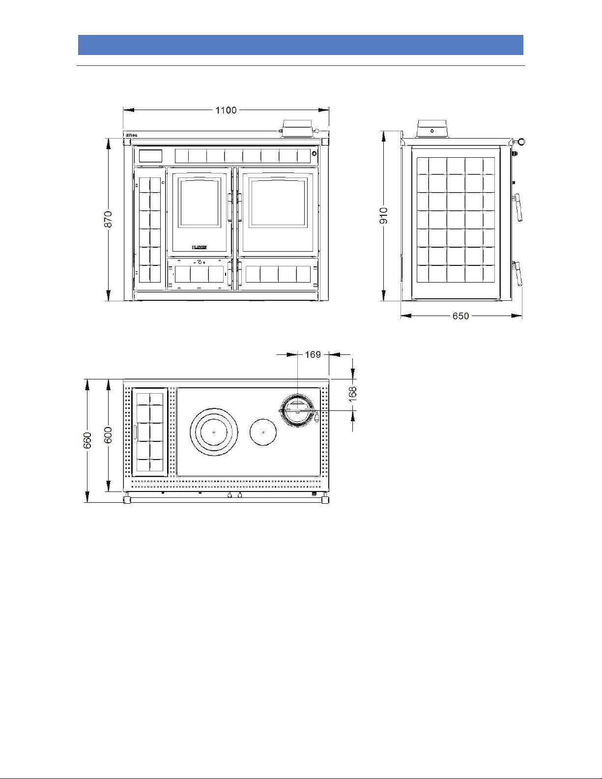
Overall dimensions
Page 12
WOOD BURNING BOILER COOKER ALTEA 110 SICURO TOP
9
EN - Rev. 1.2
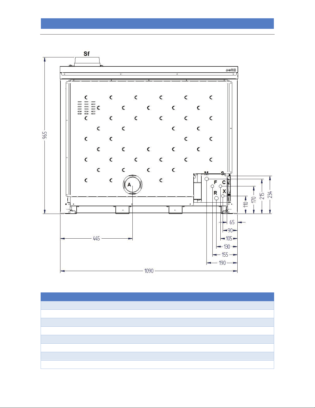
Connections data sheet
Description of connections
M = System Delivery
3/4" F
R = System Return
3/4" M
F = Domestic cold water inlet (on prepared models only) and boiler unit and system load
1/2" M
C = Domestic hot water outlet (on prepared models only)
1/2" M
X = Safety valve drain
1/2" F
S = Boiling discharge
3/4" M
A = Intake pipe
100 mm
Sf = Flue gas outlet
150 mm M
REAR VIEW
Page 13

WOOD BURNING BOILER COOKER ALTEA 110 SICURO TOP
10
EN - Rev. 1.2
Technical Specifications
Nominal heat input
kW (Kcal/h)
34.9 (16.8)
Nominal thermal output
kW (Kcal/h)
29.3 (14.7)
Nominal power released to heating water
kW (Kcal/h)
22.1 (8.2)
Nominal power delivered to room due to radiation
kW (Kcal/h)
7.2 (6.5)
Efficiency at thermal nominal power
%
84 (87.7)
CO at 13% oxygen at nominal thermal power
%
0.112 (0.091)
Nominal voltage
V
220
Nominal frequency
Hz
50
Expansion vessel litres/preloading bar
6 / 1
Maximum operating/recommended pressure
bar
2.5 / 1.5
Flue outlet diameter
mm
150
Minimum chimney draught at nominal thermal power
Pa
12 (11.4)
Combustion gas mass at nominal thermal power
g/s
17.4 (16.5)
Average exhaust flue gas temperature at nominal thermal power
°C
177 (138)
Hourly wood consumption *
kg/h
8 (3.84)
Wood loading interval *
min
60 (46)
Boiler unit capacity
litres
50
Width
mm
1100
Height
mm
870
Depth
mm
600
Minimum safety distance from flammable materials
mm
200
Weight of model with majolica sides
Kg
350
*Wood consumption is subject to the quality and dryness of the wood (4.375 kWh/kg).
The values in parenthesis (...) indicate the figures obtained in accordance with standard EN 13240.
Types of wood
Wood is one of the most precious materials offered by nature. For heating purposes, it must be verified that the features
of the wood satisfy some important requisites that must not be ignored, the most important of which is without a doubt
the correct seasoning or drying, in other words the wood must have the correct amount of humidity, around 10-15%,
therefore also the period of the year in which it is felled becomes important. This should coincide with the winter period.
Correct seasoning (at least 2 years) provides fuel with an excellent yield that is not very pollutant.
It must be kept in covered, well-aired places, already cut into pieces of a suitable size for the appliance.
The wood is divided into softwood and hardwood on the basis of the weight kg of a cubed metre of material. Softwoods
weighing 300-350 kg/m3 include fir, pine, poplar, European alder, chestnut and willow, while hardwoods weighing 350400 kg/m3 include beech, ash, elm, acacia and oak.
Softwood ignites easily, burns quickly, produces a long flame and is used in ovens requiring a long flame pass.
Hardwood is more compact, the combustion is slower with short flame, it lasts longer and is more suitable for domestic
central heating.
The wood to be burned for heating purposes has different features according to the plant variety from which it is
obtained. Not all woods are equal, and the drying time and the calorific value vary from plant to plant. The calorific value
depends on the humidity and density of the wood. Top quality woods are beech, ash, elm and acacia. Avoid resinous
woods as they reduce the appliance's service life.
Resinous woods generate a lot of soot and require the flue and the appliance to be cleaned more frequently. The
calorific value of the different types of wood depends greatly on their humidity and consequently the power of the
Page 14

WOOD BURNING BOILER COOKER ALTEA 110 SICURO TOP
11
EN - Rev. 1.2
appliance is directly affected by the type of wood used, on average a well-seasoned wood has a calorific value of 3200
kcal/kg.
Calorific value of wood in relation to humidity:
CALORIFIC VALUE of the wood means the amount of heat yielded during combustion, referring to the unit quantity of
the material burned.
The calorific value of a wood species depends on the presence of lignin (6000 Kcal/kg) or cellulose (4000 Kcal/kg) as
well as the abundance of resin (8500 Kcal/kg).
The calorific value per unit of weight ( = absolute) is highest in Conifers.
- Absolute calorific value of conifers: 4700 Kcal/kg
- Absolute calorific value of broad-leaved species: 4350 Kcal/kg.
On the other hand the SPECIFIC WEIGHT of the “broad-leaved species” is greater; therefore with equal volumes
introduced into the appliance, both the weight and amount of heat available for combustion are greater; in practice the
relative calorific value is higher (referring to a unit of volume).
For example: the calorific value of the white fir is practically the same as that of the oak, but the oak has a specific
weight that is twice that of the fir. Therefore half the volume of oak must be introduced into the appliance in order to have
the same "heat" obtained from the fir.
*Calorific value
(Kcal/Kg)
**Specific weight
(Kg/m3)
WHITE FIR
4650
440
RED FIR
4857
450
MAPLE
4607
740
BIRCH
4968
650
BLACK ELM
4640
820
CHESTNUT
4599
580
TURKISH OAK
4648
900
CYPRESS
5920
620
BEECH
4617
750
ASH
5350
720
HOLM OAK
/
960
LARCH
4050
660
EUROPEAN ALDER
4700
530
FLOWERING ASH
/
760
PLANE TREE
/
690
CYPRESS POPLAR
4130
500
FALSE ACACIA
4500
790
DOWNY OAK
4631
880
* theoretical absolute value.
** wood seasoned in the air; residual humidity 12-15 %.
% of humidity
Calorific value kcal/kg
15%
3490
20%
3250
25%
3010
30%
2780
35%
2450
40%
2300
Page 15

WOOD BURNING BOILER COOKER ALTEA 110 SICURO TOP
12
EN - Rev. 1.2
REQUIREMENTS OF THE PLACE OF INSTALLATION
Positioning
The initial phase for best installation of the appliance is to determine its optimum location; the following elements need to
be considered:
- The possibility of creating an external air vent;
- The possibility of creating a straight flue, preferably coaxial to the outlet of the appliance;
- The possibility of creating piping required for the boiling discharge;
- Proximity to the main water drain and/or the boiler (if one already exists);
- Proximity or ease of connection to the water system;
- Ease of access for cleaning the appliance, the flue gas exhaust pipes and the flue.
The unit must be installed on a floor with a suitable load capacity. If the existing building does not fulfil this requirement
appropriate measures (e.g. load distribution plate) must be taken.
The minimum safety distance from flammable materials must be at least 200 mm from the sides and back of the
appliance.
Relocating the appliance should not be done by forcing on the handle, glass or ceramics/steel sides.
The installation must guarantee easy access for cleaning the appliance, the flue gas exhaust pipes and the flue, and any
subsequent maintenance operation by the Authorised technical assistance centre.
Once you have found the best location for the appliance, position it following the instructions given below.
Furniture and movable objects must be positioned at least 15 cm from the side surfaces of the appliance; these objects
must be moved when performing maintenance on the appliance.
Protect all structures that can catch fire against the radiated heat of the fire.
External air intake
During operation, the appliance takes in air from the environment in which it is installed; It is therefore essential that this
air is replaced through an external air vent. The absence of the air vent may affect the flue draught and therefore the
combustion and the safety of the appliance.
Therefore it is mandatory to install an external air vent with a minimum completely free passage of at least 80 cm2
(round hole with minimum diameter of 15 cm protected with a special fixed large mesh grid).
It is recommended to drill the hole in immediate proximity to the appliance.
If it not possible to put the external air vent in the same room as where the appliance is installed, this hole can be made
in an adjoining room as long as this room communicates permanently, by means of a transit hole (15 cm minimum
diameter).
The hole must be protected externally with a fixed grille. The protective grille must be checked periodically to ensure that
it is not obstructed, thereby impeding the passage of air. Therefore keep the air vents clear of obstructions.
The UNI 10683 Standard FORBIDS the drawing of combustion air from garages, warehouses storing combustible
materials, or from business premises with a fire hazard.
If there are other heating or extraction devices inside the room, the air vents must guarantee a sufficient amount of air for
properly operating all the devices.
Only sealed appliances (e.g. C type gas appliances, according to the UNI 7129 Standard) or appliances that do not
cause a lower pressure compared with the external environment can pre-exist or be installed in the place where the
appliance is installed.
Extractor fans can cause malfunctions to the appliance if used in the same room.
Page 16
WOOD BURNING BOILER COOKER ALTEA 110 SICURO TOP
13
EN - Rev. 1.2
The flue and connection to the same
The flue is an essential element for the efficient operation of the appliance. The boiler cooker smoke outlet is 150 mm in
diameter. The flue must have a minimum cross section of 180 mm with a minimum height of 4 metres. Each product
must be equipped with its own flue, without other adjoining elements (boilers, chimneys, stoves, etc.). The flue
dimensions are closely related to its height, which must be measured from the appliance flue gas outlet to the base of
the stack. In order to guarantee adequate draught, the surface of the chimney flue outlet must be double the flue crosssection. The discharge pipe for combustion products generated by the forced draught device, must comply with the
following requirements:
- It must seal off the combustion gases, as well as being waterproof and suitably isolated and insulated in relation to
the conditions of use (refer to UNI 9615);
- It must be made of suitable materials capable of withstanding normal mechanical stress, heat, and the effects of
combustion gases and condensate, if any;
- It must go upwards after the vertical section, for the entire remaining part, with a minimum gradient of 20%. The sub-
horizontal section must not have a length greater than ¼ of the effective height H of the flue or chimney, and must
not be longer than 2,000 mm;
- It must preferably have a round internal cross-section: square or rectangular cross-sections must have rounded
corners with radius not inferior to 20 mm;
- It must have a constant, free and independent internal cross section;
- Rectangular cross-sections must have a maximum ratio of 1.5 between the sides;
- If the flue is installed externally, it must be insulated in order to prevent the flue gases from cooling and allowing
condensation to form;
- Parts made from non-combustible materials (it is absolutely prohibited the use of aluminium flue) - capable of
withstanding combustion gases and potential condensation - must be used for mounting the flue gas pipes (for the
section from the appliance to the flue inlet);
- It is forbidden to use fibre cement pipes to connect the appliance to the flue;
- Flue gas conduits must not pass through rooms in which the installation of combustion devices is prohibited;
- The flue gas conduits must be assembled in such a way as to guarantee adequate sealing of flue gases during low
pressure operation of the appliance;
- The installation of horizontal sections is prohibited;
- It is prohibited to use counter sloping elements;
- The flue gas pipe must allow for the recovery of soot or be cleanable, and must have a constant cross-section;
- It is forbidden to allow other air intake conduits and system pipes to transit inside the flue gas pipes, even if they are
over-sized.
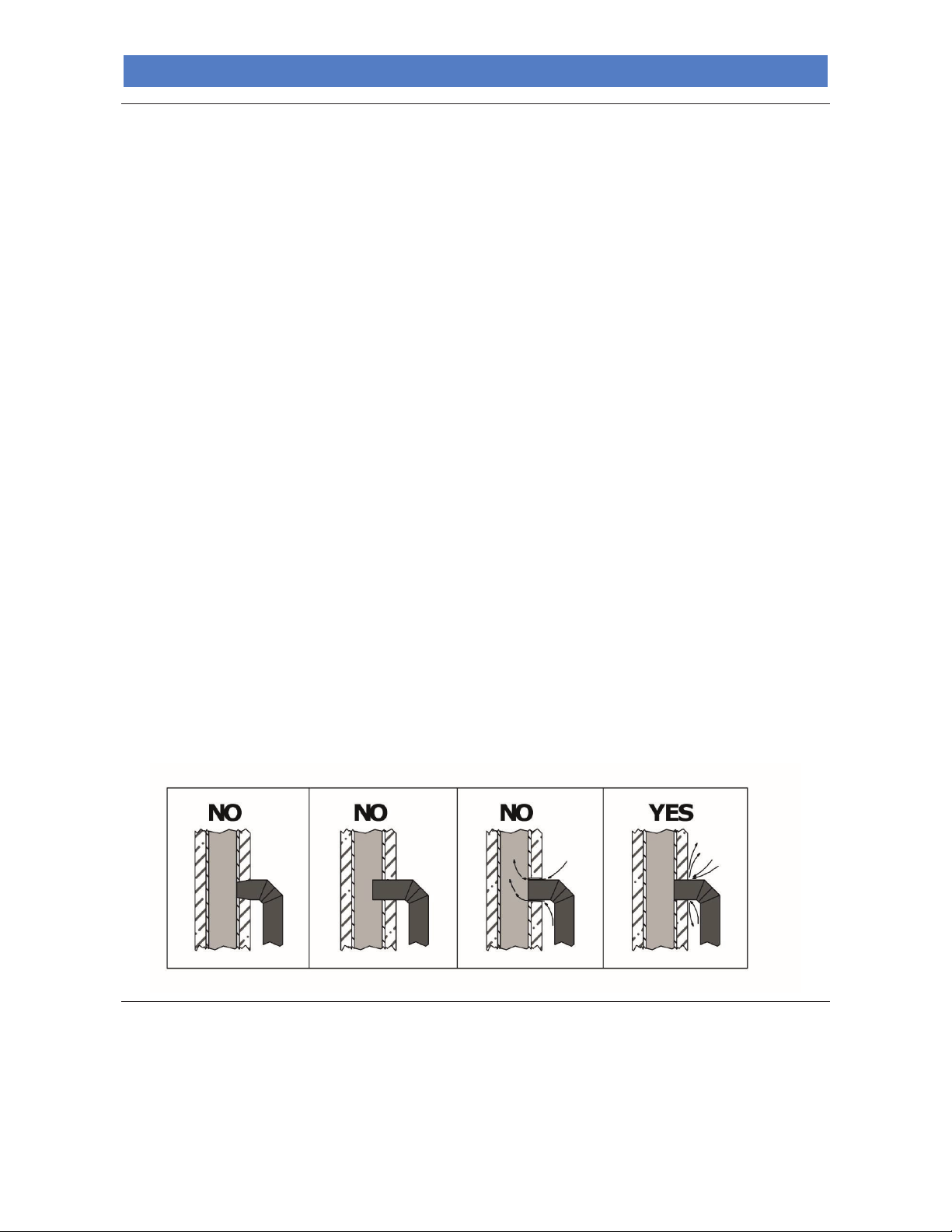
Below are examples of pipe connections to the flue:
Chimney
The chimney is a device crowning the flue, used to ease dispersion of combustion products.
It must satisfy the following requirements:
- It must have a usable outlet cross-section no less than double that of the flue onto which it is inserted;
- In must be shaped in such a way as to prevent rainwater or snow from seeping into the flue;
- It must be built in such a way as to ensure the discharge of combustion by-products even in the event of winds from
every direction and inclination.
Page 17
WOOD BURNING BOILER COOKER ALTEA 110 SICURO TOP
14
EN - Rev. 1.2
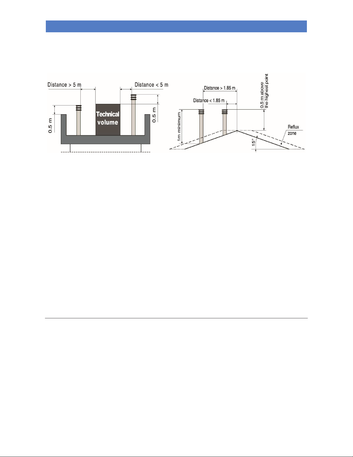
The outlet height (where height refers to the top of the flue, regardless of any chimney stacks) must be outside of the socalled reflux zone, in order to prevent the formation of counter-pressures preventing the free discharge of combustion
by-products into the atmosphere.
It is therefore necessary that the minimum heights - indicated in the following diagrams - are observed:
ELECTRICAL CONNECTION
The electric connection must only be performed by qualified staff, in compliance with all general and local safety
standards.
Check that the power supply voltage and frequency correspond to 230V – 50 Hz.
The appliance's safety is ensured when it is properly connected to an efficient earthing system.
In the electric connection to the mains power supply, include a 6 A – Id 30 mA differential trip-switch with suitable
breaking load. The electric connections, including the earth connection, must be made after shutting off the electrical
system.
When completing the system, bear in mind that the cables must be laid in an unmovable manner and far from parts
subject to high temperatures. During the final wiring of the circuit, only use components with a suitable electrical
protection rating. Do not pass electric cables in the immediate vicinity of the flue gas pipe, unless they are insulated with
suitable materials. Connection to the mains power supply should only be carried out after the wires have been connected
to the terminal board.
KLOVER srl declines all responsibility for injury to persons and animals or damage to objects due to failure to
connect the appliance to earth or to comply with IEC specifications.
Electronic control unit
The electric control unit installed on the appliance controls the heating pump, switches the motorised three-way valve
fitted on the water system, switches the heat generator ON and OFF (if installed) and starts any additional pumps.
It is composed of:
- Master switch (used to supply power to the control unit itself);
- Pump adjustable thermostat (used to activate or deactivate the pump on reaching, or not, the temperature we set
on the thermostat itself);
- Valve adjustable thermostat (used to exchange any motorised valve on reaching, or not, the temperature we set on
the thermostat itself. It is normally used for DHW in combination with another heat generator);
- AUX adjustable thermostat (used to control whether or not the heat generator reaches the temperature set on the
thermostat);
- SERV adjustable thermostat (used to activate or deactivate an additional pump on reaching, or not, the
temperature set on the thermostat);
Page 18
WOOD BURNING BOILER COOKER ALTEA 110 SICURO TOP
15
EN - Rev. 1.2
- Thermometer (indicates the temperature of the water inside the boiler unit);
- Acoustic alarm (activated whenever the boiler water temperature reaches 90-95°C);
- Level switch (indicates that water is not up to level inside the boiler).
Two cables exit the control unit, one of which has no plug. The cable with the plug should be connected to a mains
socket with the specifications detailed above. The insulated cable with 4 wires should be connected to the motorised
three-way valve installed in the domestic water system
(see section “Control of a possible three-way motorised valve for
the DHW system”).
The control unit has an internal fuse T 3,15A.
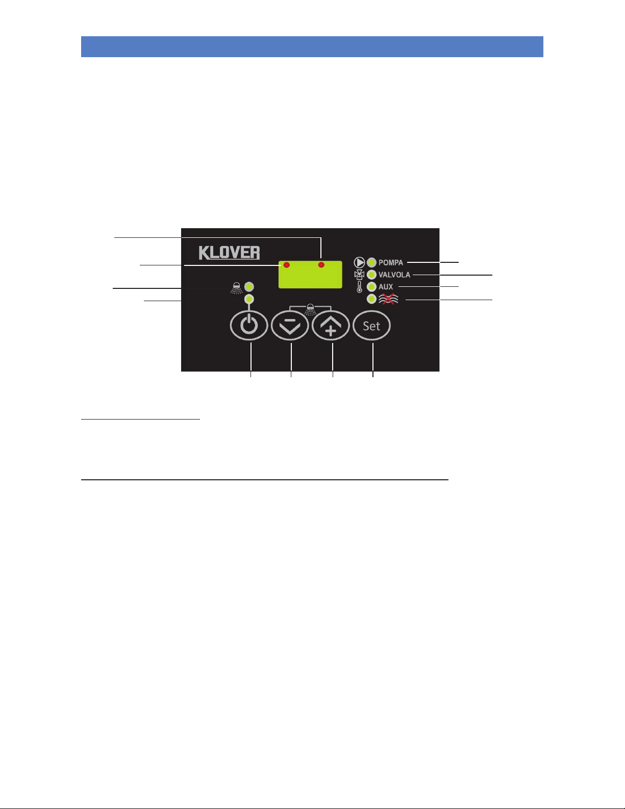
DESCRIPTION OF THE KEYS
- P1 ON/OFF
this button, when pressed for two consecutive seconds, switches the control unit on/off, depending on whether it is off or
on respectively.
During normal operation of the appliance, the control unit must ALWAYS be switched on.
- P2 DECREASE TEMPERATURE
Depending on which thermostat is selected, it decreases the value set.
If pressed at the same time as P3, it activates the DHW function.
- P3 INCREASE TEMPERATURE
Depending on which thermostat is selected, it increases the value set.
If pressed at the same time as P2, it activates the DHW function.
- P4 SET/MENU
Provides access to the set thermostat values signalled by the associated PUMP / VALVE / AUX / SERV LEDs flashing.
It also allows you to save changes made to the values for each thermostat.
P1
P2
P3
P4
L1
L2
L3
L4
L7
L8
L5
L6
Page 19
WOOD BURNING BOILER COOKER ALTEA 110 SICURO TOP
16
EN - Rev. 1.2
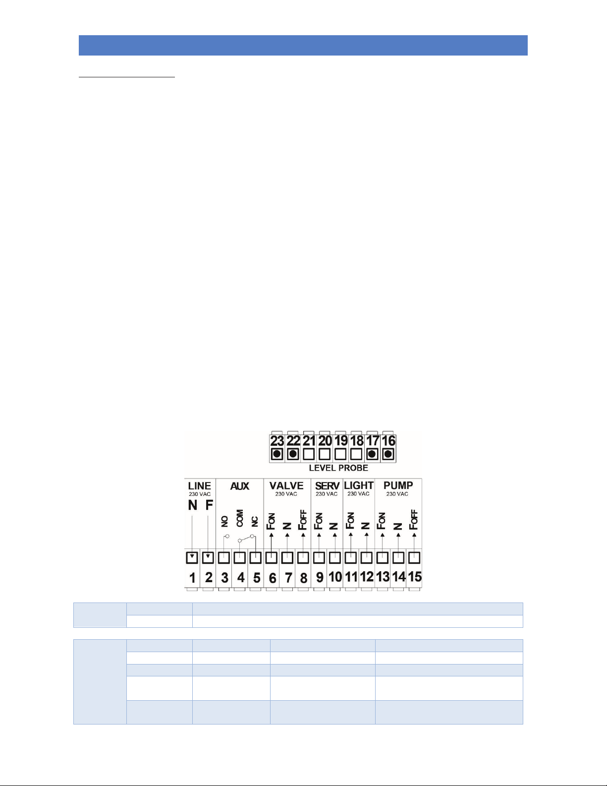
DESCRIPTION OF LEDS
- L1 PUMP LED
The led turns on when the pump thermostat is selected.
The LED lights up when the pump thermostat temperature setting is reached.
- L2 VALVE LED
The LED turns on when the valve thermostat is selected.
The LED lights up when the valve thermostat temperature setting is reached.
- L3 AUX LED
The LED flashes when the auxiliary thermostat is selected.
The LED lights up when the auxiliary thermostat temperature setting is reached.
- L4 LEVEL SWITCH LED
The LED turns on when the tank is empty or the water level is too low.
- L5 OFF LED
This LED is lit when the control unit is off.
- L6 DHW LED
This LED flashes when the DHW function is being set.
The LED is lit when the DHW function is on.
- L7 SERV LED
The LED lights up when the service thermostat is selected (for additional pump).
The LED lights up when the service thermostat (for additional pump) temperature setting is reached.
- L8 OVEN LIGHT LED
The LED is lit when the light inside the oven is on.
Inputs
PROBE
Water Probe: Temperature Range 0 – 120 °C
H2O LEVEL
ON/OFF contact: Level switch
Outputs
PUMP
System pump:
230 VAC power supply
Terminal clamps 13(FON) - 14(N)
LIGHT
Oven light:
230 VAC power supply
Terminal clamps 11(FON) - 12(N)
SERV
Service:
230 VAC power supply
Terminal clamps 9(FON) - 10(N)
VALVE Valve: 230 VAC power supply
Terminal clamps 6(FON) - 7(N) -
8(FOFF)
AUX Auxiliary: Free contacts
Terminal clamps 3(NO) - 4(COM) 5(NC)
Page 20

WOOD BURNING BOILER COOKER ALTEA 110 SICURO TOP
17
EN - Rev. 1.2
OPERATION
- ON/OFF:
The control unit is switched on/off by pressing and holding the P1 (ON/OFF).
The L5 LED turns on to indicate the OFF status.
- SAFETY function:
If the temperature detected by the H2O PROBE exceeds the value of the Safety Thermostat, this forces the activation
of the PUMP.
- ALARM function:
If the temperature detected by the H2O PROBE exceeds the value of the Alarm Thermostat, this activates the acoustic
and visual signal.
SILENCE: pressing any button deactivates the acoustic signal for 5 minutes.
- FROST PROTECTION function:
If the temperature detected by the H2O PROBE goes below the value of the ANTIFREEZE Thermostat, this activates
the timed PUMP outlet.
The relative L1 LED turns on and ICE starts flashing on the display.
- PUMP ANTI-LOCKING programme:
In the event of inactivity of the PUMP outlet for longer than the ANTILOCKING Timer, this activates the outlet of the
PUMP.
The relative L1 LED turns on and bLP appears on the display.
- STANDBY function:
If the device is OFF and in SECURE mode, the device automatically positions itself to ON status.
- PUMP TEST function:
Pressing and holding the P3 key activates the PUMP outlet until the button is released. The display will show tSt.
- LEVEL SWITCH function:
The closure of the input closure determines the activation of the L4 LED.
- OUTLET function:
§ PUMP ON: for temperatures above the PUMP thermostat setting
for temperatures above the ALARM thermostat setting
for temperatures below the ANTIFREEZE thermostat setting
§ VALVE ON: for a temperature above the VALVE Thermostat temperature
§ AUX ON: for a temperature above the AUX Thermostat temperature
§ SERV ON: for temperatures above the Thermostat setting
- DHW function:
By holding down the P2 (-) and P3 (+) buttons at the same time it is possible to activate the DHW function. At this point,
while the L6 LED flashes, simply set the time (in minutes) for which you want to have all the heat burned for the
production of domestic hot water. This function turns the pump off for the set time in minutes. When this function is
active, the pump will turn on only if the safety temperature of 85 ° C is reached. It is possible to deactivate this function
by holding down the P2 (-) and P3 (+) buttons again.
- OVEN LIGHT function
The light inside the oven light can be switched on by pressing the P4 (Set) button for 5 seconds. At this point, while the
L8 LED is flashing, set the time (in minutes) for the time chosen for the light to remain on. The oven light can be
switched off before this time by pressing and holding the P4 (Set) button once again.
Page 21
WOOD BURNING BOILER COOKER ALTEA 110 SICURO TOP
18
EN - Rev. 1.2
MAIN MENU
With a simple click of the P4 (SET) button, it is possible to scroll though the values of the set Thermostats signalled by
the flashing of the associated PUMP / VALVE / AUX LED.
To change the value:
- Go to the Thermostat value to be changed.
- By using the P2 (-) and P3 (+) buttons, it is possible to increase/decrease the value.
- To save the change, press P4 (SET).
- To exit the menu, press P1 (ESC) or wait for 5 seconds.
Parameters
Symbol
Min
Factory
setting
Max
Recommended
values
Reference led
PUMP thermostat A01 50 °C
55 °C 85 °C
Minimum 55 °C
L1
VALVE thermostat A02 20 °C
65 °C 85 °C
65 °C
(only if connected)
L2
AUX thermostat A03 20 °C
85 °C 85 °C
50 °C
(only if connected)
L3
SERV thermostat A04 20 °C
85 °C 85 °C
60 °C
(only if connected)
L7
FAULT SIGNALLING AND ALARMS
The control unit signals faults associated with the H2O PROBE via a flashing message:
- Lo: indicates a value below the set scale (temperature below 0°C).
Occurs when the H2O PROBE is off.
- Hi: indicates a value above the set scale (temperature above 100°C).
Occurs when the H2O PROBE has had a short circuit.
PARAMETER SETTINGS
PROGRAMMABLE PARAMETERS
ANTIFREEZE activation thermostat
[°C]
6
SAFETY activation thermostat
[°C]
85
ALARM function activation thermostat
[°C]
90
PUMP thermostat hysteresis (A01)
[°C]
3
VALVE thermostat hysteresis (A02)
[°C]
3
AUX thermostat hysteresis (A03)
[°C]
3
SERV thermostat hysteresis (A04)
[°C]
3
ANTILOCKING timer
[h]
168
ANTILOCKING pump activation time
[sec]
30
ANTIFREEZE Pump OFF time
[min]
5
ANTIFREEZE Pump ON time
[sec]
20
Type of Probes (10K blue=’0’ - 100K grey= ‘1’)
no.
0
STANDBY enabling
no.
1
ANTIFREEZE function enabling
no.
1
NON-PROGRAMMABLE PARAMETERS
ANTIFREEZE thermostat hysteresis
[°C]
1
SAFETY thermostat hysteresis
[°C]
1
ALARM thermostat hysteresis
[°C]
1
Page 22

WOOD BURNING BOILER COOKER ALTEA 110 SICURO TOP
19
EN - Rev. 1.2
TECHNICAL SPECIFICATIONS
Power supply
230 VAC ±10%~50Hz
Protective fuse T3,15A
Mechanical
dimensions
Built-in temperature controller: 140 x 80 x 35 mm
Temperature probe
silicone/PVC cable
Operating temperature: -50°C /130°C
Measurement limits: 0 - 99°C – Precision: ± 1°C
Outputs
PUMP output: Power supply - 230 VAC – Max capacity 5 A 250 VAC
VALVE output: Power supply - 230 VAC – Max capacity 5 A 250 VAC
AUX output: Free contact – Max capacity 5 A 250 VAC
SERV output: Power supply - 230 VAC – Max capacity 5 A 250 VAC
Standards applied
EN 60730-1, 50081-1 / EN 60730-1 A1, 50081-2
Control of any coupled boiler
If the wood-burning appliance is to be coupled to a previously installed boiler in the system (e.g. wall-hung gas boiler),
the latter can be switched on and off via the AUX thermostat in the control unit. The coupled boiler will switch on/off once
it has reached the temperature set on the AUX thermostat. This way, there will never be two heat generators operating
at the same time on the same system, thus maximising performance and management of the system itself. The coupled
boiler may however be used for the production of domestic hot water.
The contact on the two terminals at the back of the control unit (TERMINAL 4 COM and TERMINAL 5 NC) is
normally closed if the temperature of the wood-burning appliance is lower than that set on the AUX thermostat.
The contact is closed only when the temperature set on the same thermostat is reached.
It is therefore necessary to connect the two terminals (TERMINAL 4 COM and TERMINAL 5 NC) to the input of the room
thermostat on the coupled boiler (depending on the coupled product) as shown in the example below:
Control of a possible three-way motorised valve for the DHW system (on applicable models only)
The wood-burning appliance is equipped as standard with a control for a possible three-way motorised valve to be
installed on the domestic water circuit. In the rear technical compartment of the appliance there is a 4-wire cable
(See
section “Components of the appliance”)
, to be used to control the valve. The four wires in the cable have different
colours, and precisely:
- Grey or blue wire = COMMON THREE-WAY VALVE - Neutral
- Black wire = WOOD-BURNING APPLIANCE SIDE - Valve opening phase
(wire has power until temperature set on valve thermostat is reached or exceeded)
- Brown wire = COUPLED BOILER SIDE (e.g. gas boiler) - Valve close phase
(wire has power below temperature set on valve thermostat)
- Yellow / green wire = EARTH
Page 23
WOOD BURNING BOILER COOKER ALTEA 110 SICURO TOP
20
EN - Rev. 1.2
Note that the plumbing connection must be done in such a way that when the valve is at rest, the domestic water passes
from the coupled gas. Only when the wood-burning appliance temperature is sufficiently high (value set via control unit
on valve thermostat) is the three-way valve powered, closing the water circuit in the coupled boiler and opening the
water circuit in the wood-burning appliance.
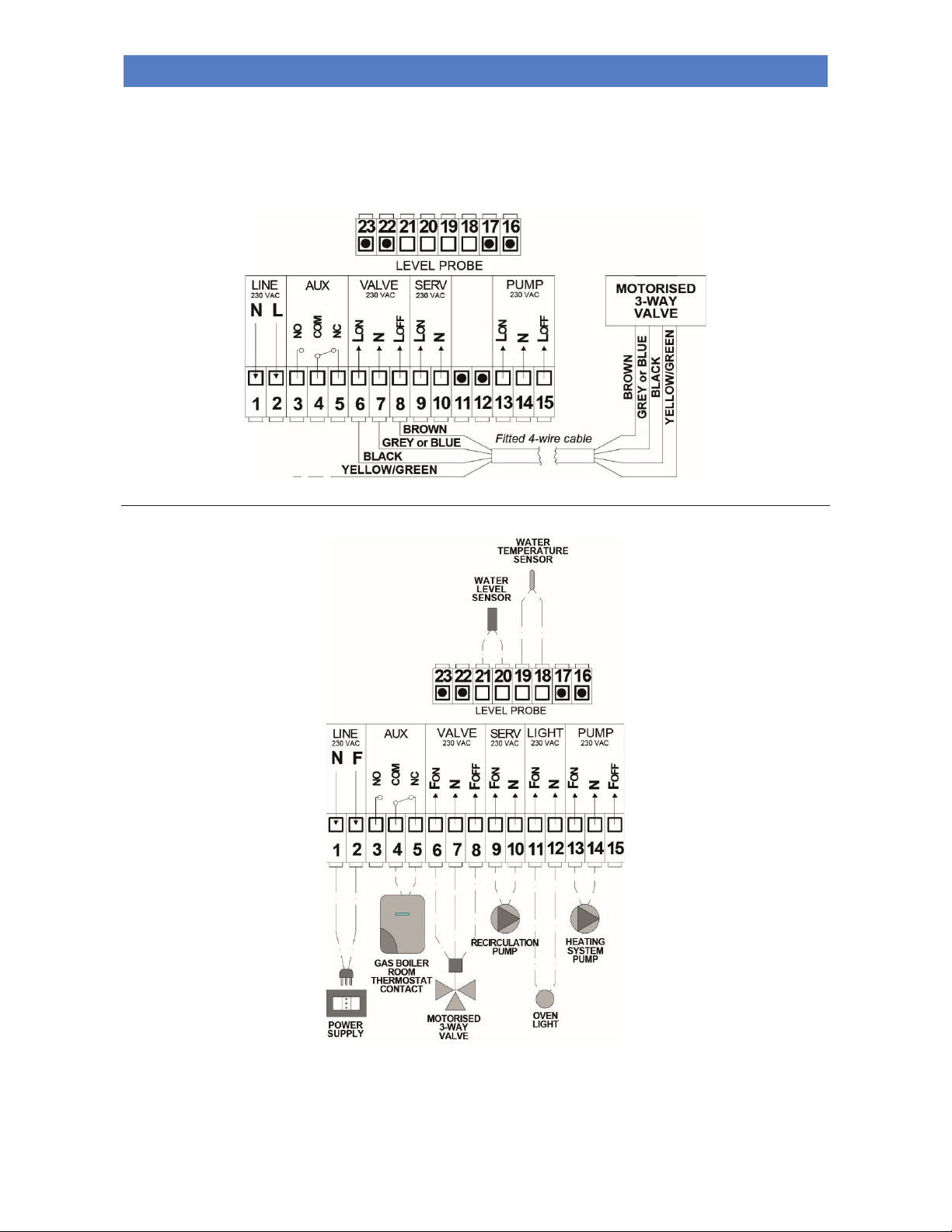
Below is an example of connection to the three-way: motorised valve:
Example of electrical connection
- LINE: Connect terminals 1 and 2 to the electrical power supply (terminals already connected to power supply cable
in the factory).
- AUX: This is used to control a boiler coupled with the heating system where present. Connect terminals 4 and 5 (or 3
and 4 depending on the type of connection to the coupled boiler) to the RT. (Room Thermostat) contact on the boiler.
Page 24
WOOD BURNING BOILER COOKER ALTEA 110 SICURO TOP
21
EN - Rev. 1.2
It is then possible to control the coupled boiler using the temperature set on the AUX thermostat; above the set
temperature the coupled boiler turns off and comes on again only below the set temperature.
- VALVE: Connect terminals 6, 7 and 8 to the three-way motorised valve.
This is used to control a motorised three-way valve (or two motorised two-way valves) installed on the DHW system.
The valve opens the DHW circuit on the wood-burning appliance at temperatures higher than those set on the
VALVE thermostat (230V voltage on terminals 6 and 7) and closes the DHW circuit at lower temperatures (230V
voltage on terminals 7 and 8). (Terminals already connected at the factory to a cable suitable for connection to a
three-way valve).
- SERV: Connect terminals 9 and 10. This is to control an additional pump installed inside the appliance. The
additional pump will operate at temperatures higher than those set on the SERV thermostat. If connected to an
additional pump, we recommend setting the SERV thermostat to temperatures no lower than 55°C to prevent the
formation of condensation, which would damage the appliance's boiler unit.
- LIGHT: Connect terminals 11 and 12 to the light inside the oven. This is to control the oven light. The oven light is
operated by holding down the button for 5 seconds P4 (Set). (Terminals already connected to the oven light in the
factory).
- PUMP: Connect terminals 13 and 14 to the pump on the heating system. This is used to control the pump installed
on the heating system. The heating pump will operate at temperatures higher than those set on the PUMP
thermostat. We recommend setting the pump thermostat to temperatures higher than 55°C to prevent the formation
of condensation, which would damage the appliance's boiler unit. (Terminals already connected to pump cable in the
factory).
- PROBE: Connect the water temperature probe to terminals 18 and 19. This is to monitor the temperature of the
water inside the appliance. If the probe is not connected, the control unit's display shows “Lo”; if there is a shortcircuit in the probe, the display shows “Hi”. (Terminals already connected to H2O Probe in the factory).
- LEVEL: Connect the level switch (water level sensor) to terminals 20 and 21. This is to signal the water level in the
boiler unit of the appliance is low. (Terminals already connected to level switch in the factory).
HYDRAULIC CONNECTION
The plumbing connections must be made in a rational way using the connections on the template of the appliance.
To facilitate the connection of the pipes, all the plumbing connections have been fitted in the technical compartment,
leaving space to make the appropriate connections.
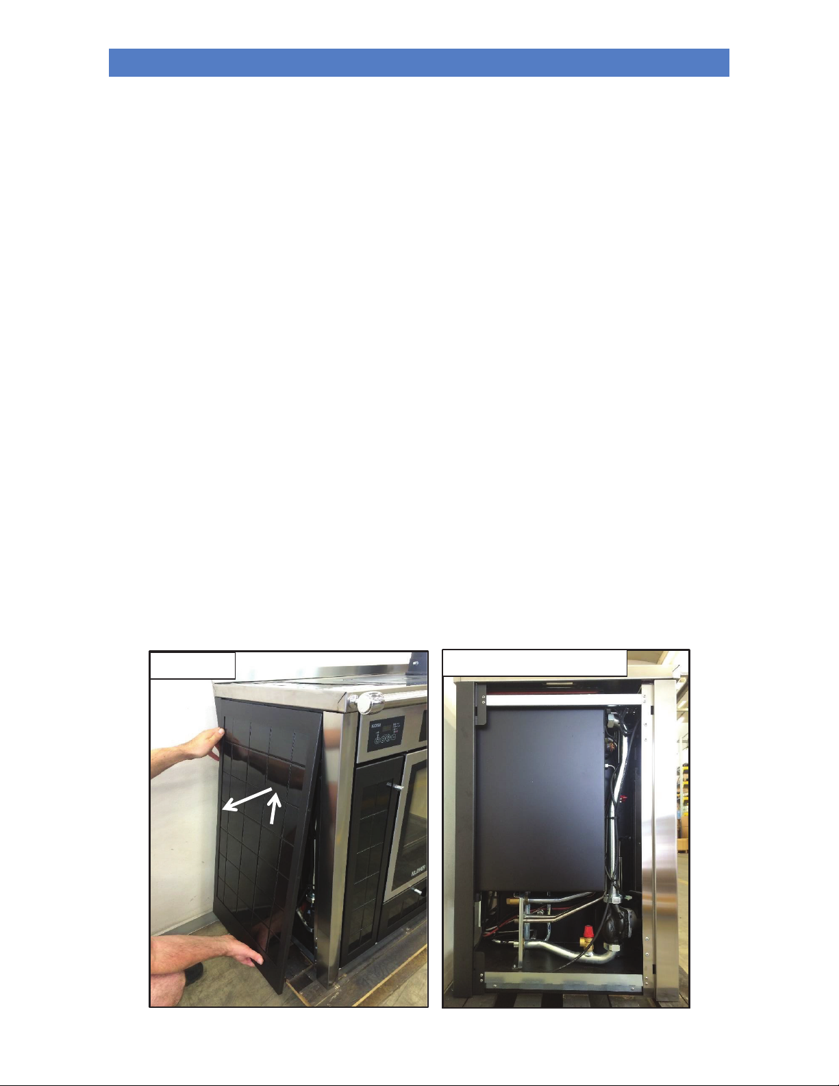
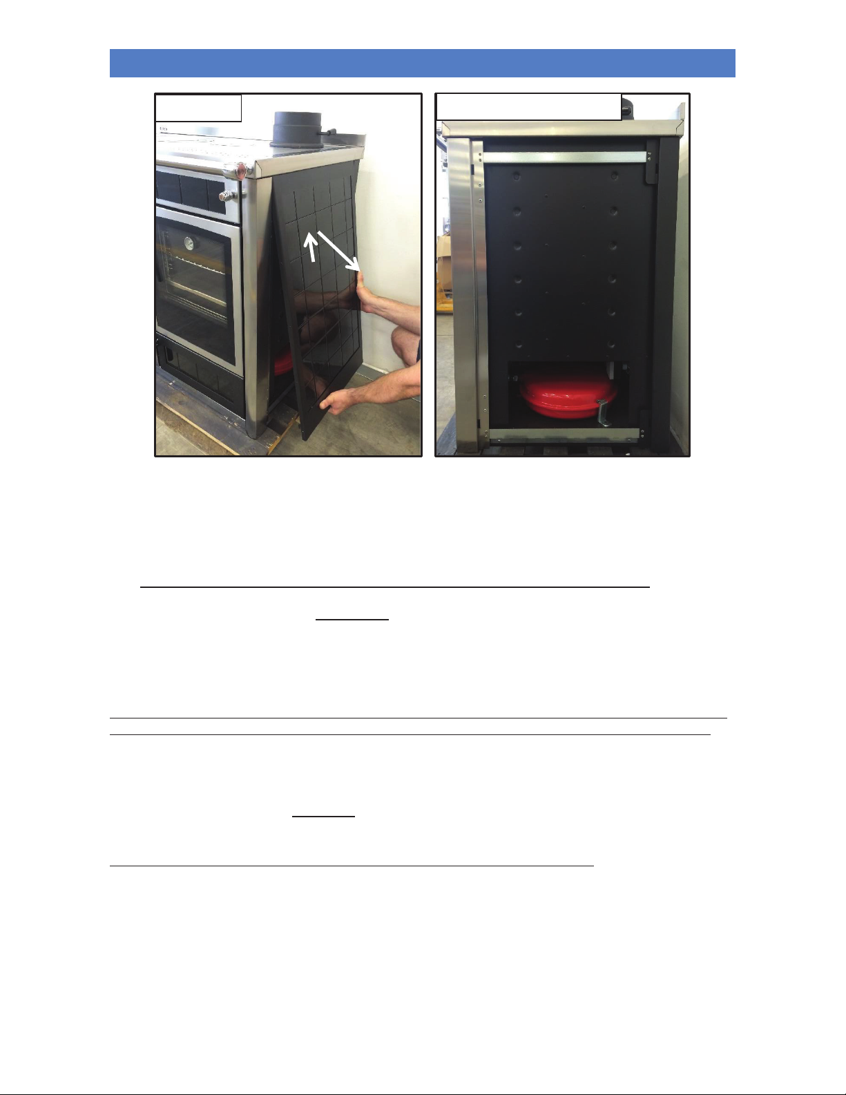
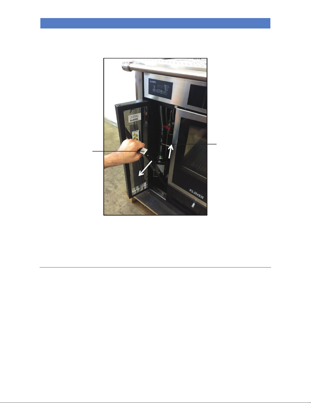
To access the unit and to make the necessary plumbing connections, proceed as follows:
2
1
LH side
LH technical compartment
Page 25
WOOD BURNING BOILER COOKER ALTEA 110 SICURO TOP
22
EN - Rev. 1.2
The appliance can be coupled with any other boiler already installed on the system. In this case it is essential to fit all the
necessary safety devices and shut-off valves based on the system and intended use. It is also necessary to consider all
laws and national, regional, provincial and municipal regulations of the country where the appliance is installed.
A safety valve calibrated to 6 bars must be installed in the DHW system.
N.B.: THE SYSTEM MUST BE DIMENSIONED FOR AN AVERAGE FLOW TEMPERATURE OF 55°C.
The maximum mains water pressure should never exceed 2.5 bar; recommended operating pressure: 1.5 bar
(during operation).
In the event of water with hardness exceeding 28 °f, an anti-limescale device must be installed. This must be
selected on the basis of the specific properties of the water.
TO AVOID COMPROMISING THE FUNCTION AND LIFE OF THE HEAT PUMP, INSTALLATION OF A FILTER AND
A MAGNETIC DIRT SEPARATOR IS REQUIRED DOWNSTREAM OF THE RETURN PIPE ON THE APPLIANCE.
You can install the appliance in the same room as another boiler only if this has a sealed chamber; installation
must be performed in compliance with the current regulations.
The appliance must be mounted exclusively by qualified personnel. Scrupulously comply with the instructions given
in this guide.
The manufacturer declines any liability for damages caused due to incorrect assembly.
1
2
1
RH technical compartment
RH side
Page 26
WOOD BURNING BOILER COOKER ALTEA 110 SICURO TOP
23
EN - Rev. 1.2
INITIAL START-UP
Filling the boiler unit and the system for the first time
After connecting the appliance to the water system, fill the boiler unit as follows:
- Dilute the Long Life product to 2% by pouring the contents of the bottle directly into the boiler unit
(See section
“Maintenance of the boiler unit”)
;
- Open the "Boiler unit loading cock" to fill the entire boiler unit until the water reaches the level of the "Boiling
discharge pipe".
N.B.: the water level inside the boiler unit should cover the exchangers (primary and/or secondary).
Regularly check that the water in the boiler unit is at the level of the "boiling discharge pipe" at 80 ° c. top up as
necessary.
The appliance is fitted with a water level sensor which signals when there is insufficient water in the boiler unit. If the
level is too low, the "Level switch - L4" LED will light up on the display
(see section “Electronic control unit”). If this
happens, fill to the appropriate level by opening the "boiling unit loading cock" and fill the boiler unit until the water level
reaches the "boiling discharge pipe".
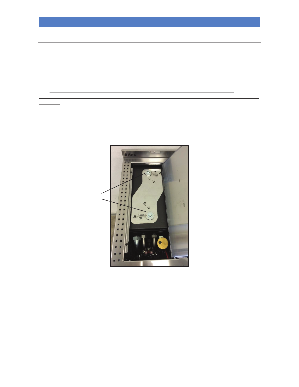
To inspect the interior of the boiler unit, remove the upper cover, placing both lock hooks to position A (Open):
After filling the boiler unit, fill the system as follows:
- Check the seal of all piping, the expansion vessel, and the circulation pump;
- Open the “automatic air release valve” on the appliance;
- Open the “and system load cock” to fill the system. Gradually allow the air to come out from the appliance through
the “automatic air release valve”; optimum working pressure is 1.5 bar (when the appliance is operating);
- Vent all radiators and any other de-aeration systems to ensure that there are no air bubbles in the system.
After installation, check the seal of all plumbing joints for the first few days of operation.
The system and the water inside the boiler unit can be emptied by opening the “boiler unit drain cock” situated at the
back of the appliance.
In a system subject to being emptied frequently, it is essential that filling is performed with water suitably treated to
remove hardness which can give rise to scaling.
Cover lock hooks.
Page 27

WOOD BURNING BOILER COOKER ALTEA 110 SICURO TOP
24
EN - Rev. 1.2
NEVER OPERATE THE APPLIANCE WITHOUT WATER IN THE BOILER UNIT. IN ADDITION TO NOT HEATING, IT
MAY ALSO COMPROMISE THE OPERATION AND LIFE OF THE APPLIANCE.
Antifreeze protection
In intensely cold periods it is good practice to leave the heating system running. In the event of a prolonged absence,
antifreeze must be added to the heating water and to the water in the boiler unit. For the choice of antifreeze and the
quantity to add to the boiler unit, see section "Maintenance of the boiler unit" in order to avoid compromising
the operation and life of the appliance.
The emptying of the heating system should also be considered. If it is being emptied frequently, it is essential that filling
is performed with water suitably treated to remove hardness which can give rise to scaling.
The boiler unit should always have treated water
(see section “Maintenance of the boiler unit”); never leave it
without water, in order to avoid rusting which would affect its life.
Switching on
Perform the following operations:
- Connect the appliance to the electrical system by using the provided cable;
- Switch on the electronic control unit by pressing button P1 “ON/OFF”;
- Make sure that there is water in the system and the boiler unit;
- set the thermostat that controls the pump to a temperature of 55-60 °C; NEVER set the temperature to lower than
55 °C because condensation could form in the boiler unit, which in time could ruin the appliance;
- Open the “upper smoke damper” on the flue inlet by setting the handle to the vertical position;
- Open the “internal smoke stream damper” by pulling the knob out fully.
- Open the “primary manual air combustion damper” by turning the knob fully to the right (+).
- Open the “secondary automatic air combustion damper” by turning the knob fully anti-clockwise.
- Light the fire using seasoned, thin wood;
- When the wood has ignited well, close the "primary manual air combustion damper" by turning the knob fully to the
left (-) and adjust the combustion air via the "secondary automatic air combustion damper", by adjusting the opening
of the relative knob;
- Close the “internal smoke stream damper” by pushing the knob in fully to increase appliance yield and to deliver
more heat to the oven. If necessary, adjust the draught in the flue by adjusting the "upper smoke damper" on the flue
inlet.
During ignition, combustion may be difficult to achieve, until the flue gas pipes and the flue are hot. Weather conditions
may also affect the way the flue draws.
The fire door must be kept closed at all times except during refuelling in order to prevent the escape of smoke.
Never light the appliance with alcohol or other highly flammable liquids.
The fire door has an opening for the flow of post-combustion air between the glass and the frame. This opening does not
assure a seal in the combustion chamber. Any smoke escaping during ignition and/or normal operation of the appliance
is not a defect, but is related to poor draught in the flue, a lack of air vents in the room or the type/quality of wood
burned.
Always remember to open the smoke damper a few seconds before loading the combustion chamber with new wood in
order to prevent the backflow of smoke into the room.
Page 28
WOOD BURNING BOILER COOKER ALTEA 110 SICURO TOP
25
EN - Rev. 1.2
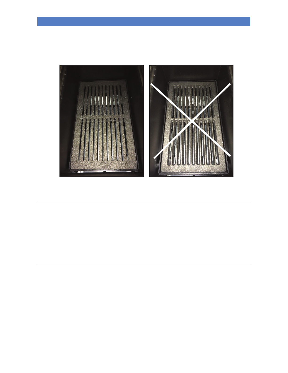
ATTENTION!!!
IN ORDER FOR THE APPLIANCE TO OPERATE PROPERLY THE CAST IRON GRATE INSIDE THE COMBUSTION
CHAMBER MUST BE POSITIONED AS SHOWN BELOW , TAKING CARE NOT TO INVERT IT, TO PREVENT THE
ASH FROM COMPACTING AND NOT FALLING INTO THE ASH DRAWER. IF THE CAST IRON GRATE IS NOT
TURNED PROPERLY, THIS WOULD AFFECT ITS LIFESPAN.
Warning: during the ignition phase and normal operation of the appliance, maintain the necessary safety
distance and do not stand in front of it.
Operation
To avoid possible damage and/or deformation to the appliance, it is essential not to load excessive amounts of fuel. It is
also recommended to burn only good quality, dry and well-seasoned wood (cut at least 2 years).
Do not, under any circumstances, burn waste and/or any fuel other than wood for burning, to avoid reducing the life of
the appliance.
To maximise the performance of the appliance during normal operation, adjust the opening of all dampers (air and
smoke) according to draught; once combustion is complete, close all smoke and combustion air dampers to retain heat
for longer.
The oven and the cooking hotplate
The appliance oven is heated by exploiting the heat of the exhaust fumes; this temperature therefore depends on the
speed of combustion and the quantity of fuel burned. To increase the temperature, an intense flame needs to be created
by burning dry, thin pieces of wood and, at the same time, opening the “manual combustion air damper”. Next, with the
fire burning well, close the “internal smoke stream damper” by pushing the relative knob in fully to divert the flow of hot
gases around the oven; in addition, adjust the opening of the “manual combustion air damper”. If necessary, adjust the
draught in the flue by adjusting the "upper smoke damper" or another damper located on the flue.
It is recommended to shift the wood every now and again using the fireside poker, in order to achieve a good flow of
combustion air inside the combustion chamber.
To achieve uniform baking, it is recommended to rotate the tray or grille inside the oven 180°. For browning, place the
dish on the highest level in the oven or, to achieve a more uniform bake place the tray or grille in the middle or lower
level of the oven.
NO
YES
Page 29
WOOD BURNING BOILER COOKER ALTEA 110 SICURO TOP
26
EN - Rev. 1.2
To achieve maximum output to the cooking hotplate, push the grate raising lever downwards. This raises the position of
the grate and brings the flame closer to the cooking hotplate; to return the grate to the low position, push the grate
raising lever stop upwards:
The flue and air inlet are the main components for ensuring the correct operation of the cooker and the cooking
hotplate.
In the event of poor flue draught caused by particularly adverse weather conditions (strong wind, low pressure,
etc.),partially close the internal smoke stream damper without closing it completely. Also adjust the smoke damper on
the flue inlet and/or the flue outlet.
Production of domestic hot water (suitable models only)
Domestic hot water is produced instantly via a double heat exchanger immersed in the water inside the appliance. To
obtain sufficient amounts of hot water, the appliance must have a minimum temperature of 65°C.
If a lot of hot water is needed, manually set the appliance to the "DHW Function" mode
(see section “Electronic control
unit”)
. The purpose of the "DHW Function" is to postpone operation of the heating pump to higher temperatures, so that
all heat is used for hot water. Hence, the circulating pump in the heating system is off during this phase. When working
in “DHW Function” mode, the timer can be set to delay the pump until 85°C is reached. This function should be disabled,
when hot water is no longer needed (see section “Electronic control unit”).
If water is particularly hard, it is essential to install an anti limescale device at the DHW exchanger inlet, to be
chosen according to the water type.
If there is a drop in the quantity or the temperature of hot water, the heat exchanger may need to be cleaned
(chemically) by the installer.
Grate raising lever.
Grate raising lever stop.
Page 30

WOOD BURNING BOILER COOKER ALTEA 110 SICURO TOP
27
EN - Rev. 1.2
Boiling
If for any reason (power cut, a pump fault, too much fuel, etc.…), the water in the boiler unit reaches boiling point, carry
out the following operations immediately:
- Fully open all smoke dampers;
- Fully close all combustion air dampers;
- Open a hot water tap and leave the water to run until the temperature in the appliance drops (models connected to
the DHW system only).
After ascertaining the reason for the high temperature, wait for everything to go back to normal (temperature below
70°C), then check the water level in the boiler unit and top up if necessary, by opening the "boiling unit loading
cock". A low water level inside the boiler unit is signalled by the “Level switch – L4” LED on the control unit
(see section
“Electronic control unit”)
.
PROBLEMS, ALARMS, USEFUL ADVICES
Useful info…
Listed below is some important information regarding the appliance:
- It is normal for the appliance to emit a smell of paint during its first few days of operation. We recommend ventilating
the installation room during the initial start-up.
- The boiler unit is treated with anti-oxidant paint in order to protect it against oxidation in the event of long periods of
inactivity. After initial start-up, this paint no longer preserves its original features and any wear of the paint inside the
combustion chamber should not be regarded as a manufacturing fault.
- Do not clean with water inside the combustion chamber; any oxidation of the combustion chamber after a long period
of inactivity is not to be considered as a manufacturing fault.
- Any perceived noise during operation may be caused by the expansion settling of the plates that make up the boiler
unit. These noises are accentuated especially during ignition and switching off phases of the appliance and are not to
be considered a manufacturing fault.
- The door of the appliance does not provide airtight closing (opening for secondary-post combustion air passage); any
perceived smoke smell (especially during ignition) is not to be considered a manufacturing fault.
- The appliance works exclusively with wood logs; do not burn different fuels.
- The appliance can work only if connected to the heating system and with water inside the boiler unit. Do not
start the appliance for any reason if a plumbing connection in compliance with current regulations has not been done
and if you have not filled the entire boiler unit and system with water in order not to compromise its life.
- If there is soot and fine particulate in the room where the appliance is installed, check the seal on the flue gas pipes
and the filter of the ash vacuum device used for cleaning.
- Clean the boiler unit regularly (at least every 2 years) by changing the water inside and removing any solid
residues. Next, fill the boiler unit with fresh water to restore the right dilution of LONG LIFE. Do not leave the
boiler unit without any water, to avoid rusting which would reduce its lifespan.
- The temperature of the thermostat that controls the pump must never, for any reason, be set below 55°C, to
prevent the formation of condensate that could corrode the internal boiler.
- When priority is to be given to DHW (prepared models only), set the "DHW Function" and burn small pieces of dry
wood in order to increase the flame and performance. After use of DHW water, disable the "DHW Function".
- Open the smoke damper before loading the wood and close the combustion air damper to prevent the release of
smoke from the fire door.
- When necessary, "move" the wood using the fire hook supplied or by adjusting the grate raising lever in order to
revive the flame.
Page 31

WOOD BURNING BOILER COOKER ALTEA 110 SICURO TOP
28
EN - Rev. 1.2
What happens if there is..
- INSUFFICIENT DRAUGHT
- POOR FLUE GAS EVACUATION
- FLUE GAS ESCAPING INTO THE ROOM
ELEMENTS TO CHECK
ORIGIN
External air intake
- Non-existent;
- Shutter closed;
- Accidental obstruction;
- Insufficient cross section.
Air intake (pipe)
- Insufficient cross section.
Combustion air damper
- Closed or incorrectly set.
Smoke damper
- Closed or incorrectly set.
Wood
- Excessive humidity.
Flue
Hood fitting/flue gas channel
- Insufficient cross section;
- Insufficient height;
-
Accidental obstructions;
-
Periodical cleaning not performed;
-
Heat insulation or insulation insufficient or non-existent;
-
Use of unsuitable materials;
-
Heat insulation or insulation absent or insufficient;
-
Inadequate cross section (square or rectangular) or incorrectly sized;
-
Narrowing or presence of obstacles to the flow of flue gas;
-
Accidental obstructions;
-
Infiltrations of parasite air due to the use of materials not impermeable
to gas and liquids;
- Insufficient height.
Chimney
- Outlet height in the reflux zone;
- Close to or adjoining other chimneys;
- Vicinity of obstacles, both natural and artificial;
- Obstruction ( e.g.: birds nests);
- Inadequate chimney pot shape;
- Insufficient emission cross section.
- CONDENSATE ESCAPING THROUGH THE MASONRY
ELEMENTS TO CHECK
ORIGIN
Flue gas channel
Flue
Condensate tray
- Use of inadequate material;
- Absence of or incorrect installation of the dedicated condensate
collector with drain connected to the disposal system.
- SELF-COMBUSTION INSIDE THE FLUE
ELEMENTS TO CHECK
ORIGIN
Hood fitting/flue gas channel
Flue gas channel
Flue
- Periodical cleaning not performed.
- WATER INSIDE THE COMBUSTION CHAMBER AND/OR THE ASH DRAWER
ELEMENTS TO CHECK
ORIGIN
Flue
Chimney
- In the event of the total or partial absence of a chimney, the flue has not
been installed parallel to the appliance;
- Unsuitable chimney.
Pump thermostat
- Pump start-up at temperatures that are too low (condensate is created).
Page 32
WOOD BURNING BOILER COOKER ALTEA 110 SICURO TOP
29
EN - Rev. 1.2
CLEANING AND MAINTENANCE
Precautions before cleaning
Before carrying out any cleaning or maintenance operations, make sure that:
- the appliance is off and has cooled down completely.
- the ash is completely cold.
- the ash vacuum device used for cleaning is suitable and its filter is in good condition.
Before re-starting the appliance, re-install all previously removed components.
During cleaning operations, use the personal protection devices specified in Directive 89/391/EEC.
The required cleaning frequency depends on the type and quality of the pellets used. The schedule indicated below may
therefore vary.
Any problem affecting the appliance caused by lack of cleaning will not be covered by the warranty. The failure
of these operations could affect the safety of the product.
Cleaning the combustion chamber
It is important to clean the combustion chamber at least once a month to ensure the proper and an optimum
performance and operation of the appliance. Please proceed as follows:
Using a small brush, remove any residue which has formed on the internal walls of the combustion chamber. Do not use
tools that can reduce the thickness of the metal sheet of the boiler unit.
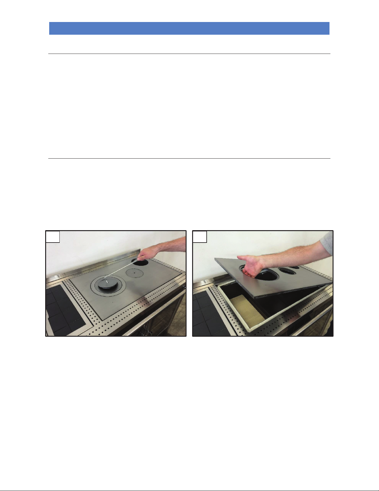
Remove the pipes connecting the appliance to the flue and clean them if necessary.
After removing the upper damper, remove the cooking rings and hotplate
(figures 1 and 2).
1
2
Page 33
WOOD BURNING BOILER COOKER ALTEA 110 SICURO TOP
30
EN - Rev. 1.2
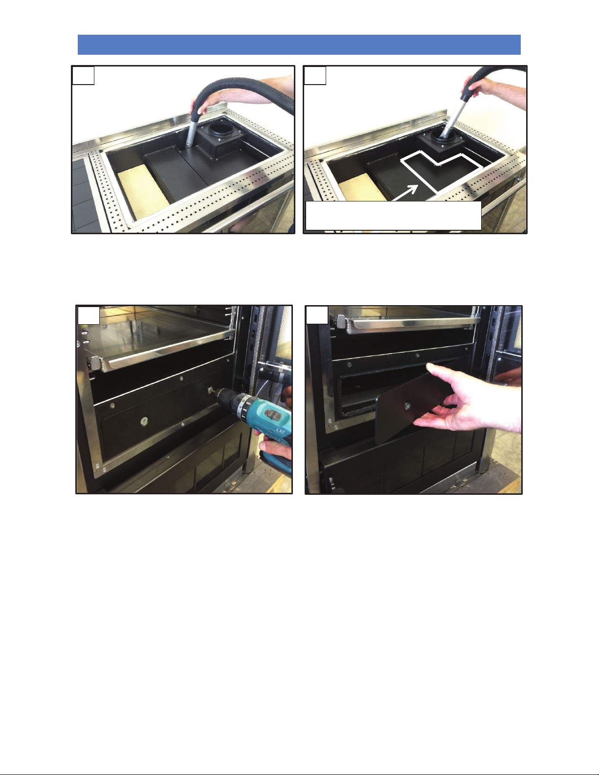
Vacuum any ash which has deposited above the combustion chamber, above and around the entire oven
(figure 3). In
addition, vacuum any ash deposited within the combustion chamber and the smoke deflector; accessing the smoke
deflector using the vacuum hose. Also vacuum ash deposited below the cooking hotplate located above the oven as
indicated in the image (figure 4). After cleaning, reassemble the components which were removed.
3
4
The cooking hotplate which requires ash to
be removed using a vacuum.
5
6
Page 34
WOOD BURNING BOILER COOKER ALTEA 110 SICURO TOP
31
EN - Rev. 1.2
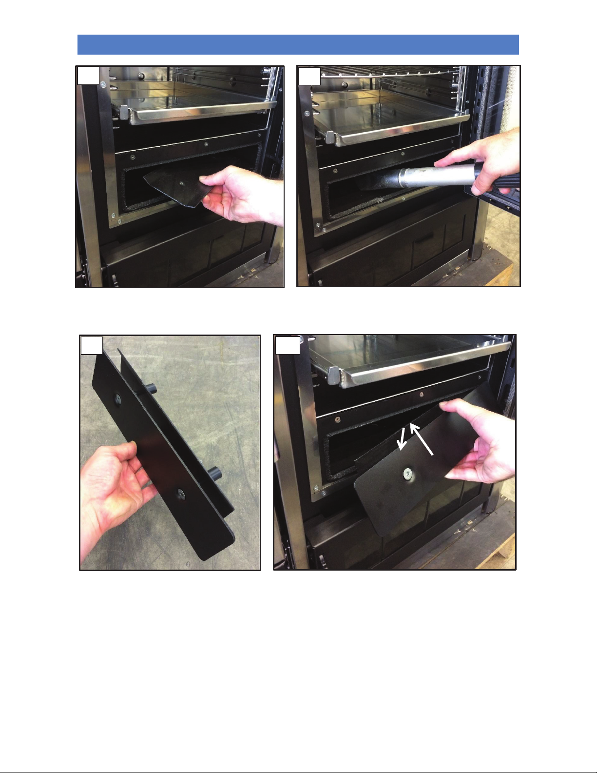
Remove the two hex screws completely in order to remove the inspection vent below the oven
(figure 5 e 6). Next
remove the counter plate which fastens the vent
(figure 7) and vacuum any ash deposited inside (figure 8).
Once cleaned, reassemble the inspection vent below the oven
(figures 9 and 10) taking care to ensure the gasket
guarantees an adequate seal against flue gases.
WARNING: use suitable ash vacuum devices equipped with a fine mesh filter in order to prevent ash from being
blown into the room and to prevent damaging the vacuum cleaner. We do not recommend the use of normal
vacuum cleaners.
Deposits on the walls of the combustion chamber (if particularly resinous wood is burned) can be eliminated by running
the appliance at maximum for 30-40 minutes (in this case set the thermostat to 80℃) with thin dry wood.
Leave the fire to go out and then scrape the inside walls using a steel spatula. Do not use tools that can reduce the
thickness of the metal sheet of the boiler unit.
7
8
2
1
9
10
Page 35
WOOD BURNING BOILER COOKER ALTEA 110 SICURO TOP
32
EN - Rev. 1.2
After a long period of disuse, check for obstructions in the flue before turning on the appliance.
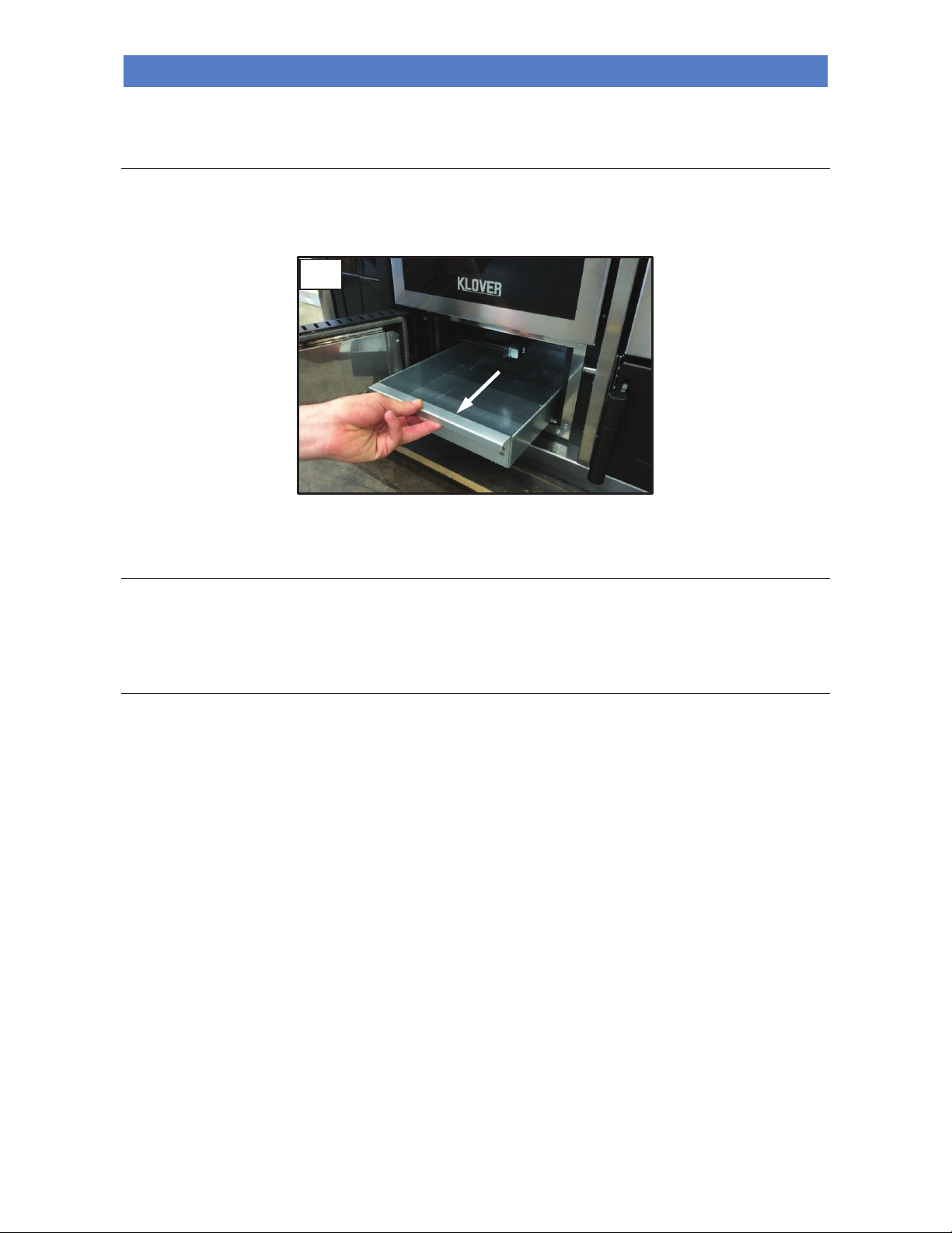
Cleaning the ash drawer
Too much combustion residue inside the ash drawer prevents the proper supply of oxygen for combustion, reducing the
performance of the appliance, as well as possibly damaging the grate inside the combustion chamber.
We recommend you periodically empty the ash drawer
(figure 11) to ensure an efficient flow of combustion air at all
times. It is also recommended to occasionally remove residual ash from the combustion chamber.
Cleaning the ceramic glass
Always clean the glass when the appliance is off and has cooled down completely. Use a damp cloth or a detergent
specifically formulated for ceramic glass. Do not use abrasive sponges. Do not clean the glass if still warm; changes in
temperature can lead to breakage.
Cleaning the cooking hotplate
The cast iron hotplate requires regular maintenance, above all if residues or liquids have deposited following its use.
It is recommended to clean the hotplate, while it is still warm. This is to allow any humidity to evaporate and prevent the
formation of rust stains; it is therefore not recommended to clean the cast iron plate when cold.
The cast iron plate should be treated with a non-acidic, oil corrosion protection. With frequent use, this layer is worn
away and the protection is lost. The formation of small rust stains may then appear, particularly in the presence of water
or other liquids. For this reason, it is necessary to reapply the non-acidic oil to the hotplate with a cloth.
If rust stains do appear, they can be removed using a slightly abrasive sponge or sandpaper. Avoid the use of
aggressive or acidic detergents.
Colour change over time should not be considered a product defect, rather it is a peculiarity of the material used.
The hotplate is subjected to continuous thermal expansions due to the increase/decrease in temperature; if removed and
replaced, ensure there is always a 2 mm gap between the hotplate and the hotplate frame surround to allow for any
thermal expansion of the hotplate.
11
Page 36
WOOD BURNING BOILER COOKER ALTEA 110 SICURO TOP
33
EN - Rev. 1.2
Cleaning the flue
The flue must be cleaned at least once a year, at the beginning of winter, and whenever it becomes necessary.
It is important to check for any obstructions in the flue before switching the appliance on following long periods of
inactivity.
If the flue is not cleaned, the operation of the appliance and its components may be compromised.
The frequency for cleaning the appliance and flue depends on the quality of wood used.
USE TOP QUALITY WOOD TO OBTAIN THE BEST RESULTS.
Maintenance
Timely and systematic maintenance is essential for guaranteeing correct operation, optimal heat performance and
durability of the device. Therefore, qualified staff should check the appliance at least once a year at the beginning of the
season.
You must periodically check the seals because the latter guarantee the air- and water-tightness of the appliance and its
good functioning; if they are worn or damaged you need to be replace them immediately by contacting a Klover
Authorised technical assistance centre.
For proper operation, the appliance must undergo routine maintenance performed by a Klover Authorised
technical assistance centre at least once a year.
Maintenance of the boiler unit
The appliance is supplied with a special additive call LONG LIFE, designed to protect the boiler unit
and heat exchangers from rust and to keep the water inside the boiler unit clean. LONG LIFE
should be diluted to 2% with water inside the boiler unit. It can be poured directly into the boiler unit
before or after filling it with water.
For ease of use, a table is provided of the annual dilution dosages of LONG LIFE:
It is recommended to empty the boiler unit water every 2 years and remove any solid residues caked on the
bottom. These residues reduce the effectiveness of LONG LIFE. The boiler unit should then be refilled and the
optimum dosage of LONG LIFE should be added. If too much LONG LIFE is added by accident, empty and refill
the boiler unit. Observance of the proper frequency for cleaning the boiler unit will prolong its life and is
essential for the validity of the warranty.
ATTENTION!!! NON-USE AND OR AN INCORRECT DOSAGE OF LONG LIFE WILL INVALIDATE THE WARRANTY
ON THE BOILER UNIT.
LONG LIFE gas been designed and tested on SICURO TOP products; KLOVER declines all liability arising from the use
of LONG LIFE in products or applications other than those indicated.
Boiler unit
water
capacity
Recommended
dose of LONG LIFE
(2%)
Recommended
dose of LONG
LIFE (1%)
after the
first year
Recommended
dose of LONG LIFE (2%)
after
the first year
50 l 1000 ml 500 ml
Empty and clean the entire
boiler unit. Next restore the
level of water content, adding
1000 ml of LONG LIFE.
Page 37

WOOD BURNING BOILER COOKER ALTEA 110 SICURO TOP
34
EN - Rev. 1.2
Contact your agent/retailer to purchase LONG LIFE.
Below are a number of special warnings for the use of LONG LIFE:
- Causes serious eye irritation.
- May cause an allergic skin reaction.
- Harmful to aquatic organisms with long-term effects.
- Avoid breathing dust/fumes/gases/fog/vapour/aerosols.
- Wear gloves/protective clothing/protect the eyes/face.
- Do not dispose of in the environment.
- IN CASE OF CONTACT WITH EYES: rinse thoroughly for several minutes. Remove contact lenses if it is easy to do
so. Continue rinsing.
- IN CASE OF IRRITATION OR SKIN RASH: consult a doctor.
- Wash contaminated clothes before wearing them again.
- Dispose of the product/container in accordance with local/regional/national/international regulations.
Dilution with antifreeze: LONG LIFE is compatible with pure glycol mixtures and always with water in any proportion.
Several antifreeze products on the market contain additives, however which may be not very compatible. To avoid
doubt, test-mix the antifreeze solution with LONG LIFE to see how it behaves. If the components are mixed gently for a
short time in the recommended proportions and then do not separate in the system, the products are compatible. If there
is heavy clouding of the mixture which does not improve by stirring, the products are not compatible.
Page 38

WOOD BURNING BOILER COOKER ALTEA 110 SICURO TOP
35
EN - Rev. 1.2
WARRANTY CONDITIONS
The warranty period starts from the date of purchase of the appliance, which must be demonstrated by a delivery
document and the warranty coupon duly completed and sent in a sealed envelope to the address of KLOVER SRL.
These documents must be shown to the Technical Assistance Centre, if required.
- A copy of the warranty coupon must be stored together with the purchase document received.
- KLOVER s.r.l. disclaims any liability for accidents resulting from failure to comply with the instructions contained the
user and maintenance manual attached to the appliance.
- Furthermore, KLOVER s.r.l. declines any liability arising from misuse of the appliance on the part of the user,
unauthorised modifications and/or repairs, as well as the use of non-original spare parts or parts not suitable for this
model.
KLOVER s.r.l. guarantees the materials, construction and operation of the appliance for 2 years, under the
following conditions:
1. On its own unquestionable judgement, the device evidencing material or construction faults will be repaired or
replaced; with the exception of all costs relating to transport, restoration (hydraulic disassembly and assembly
operations, any masonry works and any other necessary intervention) and accessory materials;
2. The warranty does not cover:
- the ceramic glass and ceramic-majolica and/or varnished steel linings, as they are very fragile and can get
accidentally damaged;
- any part made of ceramic-majolica evidencing altered colour shades, pitting, cracks, shading and slight
dimensional variations, as these cannot be regarded as product defects but features deriving from the
handmade processing techniques used;
- The cast iron brazier, the grille and cooking hotplate, smoke deflector or flame arresters, gaskets, fuses or
batteries inside the device's electronic system and any other removable component, where it is not proved that
their condition is due to a manufacturing defect rather than the effects of wear;
- electric and electronic parts, in which the malfunction can be traced to a non-compliant electrical connection,
natural disaster (lightning, electrical discharges, etc.) and variation in voltage other than the nominal voltage;
- any parameter calibration intervention due to the type of fuel or installation of the device.
3. The replaced components are guaranteed for the remaining period of the warranty, starting from the date of
purchase and/or for a period not exceeding 6 months;
4. The use of poor-quality wood pellets or other fuel could damage the components of the device thereby voiding the
relevant warranty and the manufacturer's liability. Therefore, we recommend using the fuel type indicated in our
specifications;
5. Incorrect installation carried out by unqualified personnel, tampering with, failure to comply with the instructions
contained in this "use and maintenance manual" and those regarding “workmanlike installation” shall void any
warranty rights; the same applies to damages deriving from external factors. At all events, any compensation for
direct or indirect damages is excluded, regardless of the nature and cause of the damages;
6. Please bear in mind that the goods travel under the customer’s responsibility, even if delivered carriage free,
therefore we shall not be held liable for any damages due to loading and unloading operations, accidental knocks,
storage in unsuitable places, etc.;
7. The boiler unit of water-based products only connected to a heating and/or sanitary water system is guaranteed for 5
years, at the above-mentioned conditions.
8. The warranty is only valid if the duly filled-in warranty coupon - clearly legible in all its parts - is mailed in a
closed envelope.
The competent law court for settling any disputes is the Court of Verona.
Page 39

WOOD BURNING BOILER COOKER ALTEA 110 SICURO TOP
36
EN - Rev. 1.2
Page 40

Cod. CS.IST.ALT110TOP-EN
KLOVER Srl
Via A. Volta, 8
37047 San Bonifacio (VR)
VAT No. 02324280235
www.klover.it
 Loading...