

klover DIVA SLIM Series, DIVA SLIM, DIVA SLIM WOOD Installation, Use And Maintenance, Useful Tips
Page 1

ENGLISH
DIVA SLIM pellet
boiler stove
INSTALLATION, USE AND
MAINTENANCE, USEFUL TIPS
Page 2

Page 3
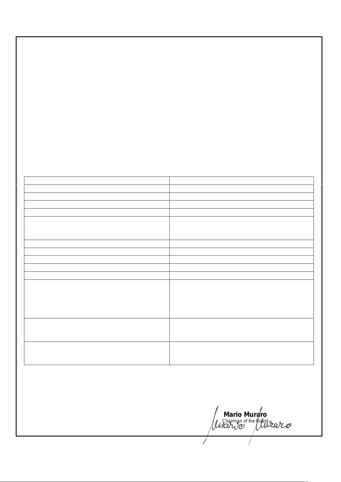
SERVICE DECLARATION
Ref. Annex III EU Regulation no. 305/2011
DoP/KLOVER-044
1. Identification number
:
DSL, DSLW
2. Model and/or lot no. and/or serial no. (Art. 11-4)
:
DIVA SLIM, DIVA SLIM WOOD
3. Intended use of the product according to the
relevant harmonised technical specification
:
Wood pellet-fired domestic heating appliance
4. Name or trademark of the manufacturer (Art11-5)
:
KLOVER s.r.l.
I - 37047 San Bonifacio (VR) – Via A. Volta, 8
5. Name and address of the representative (Art.12-2)
:
-
6. Assessment and verification system of the
performance constancy (Annex 5)
:
System 3
7. Notified laboratory
:
NB 0476
KIWA CERMET ITALIA S.p.A.
Number of test report (based on System 3)
:
2002365/C-371
8. Declared performances
HARMONISED TECHNICAL SPECIFICATION
EN 14785
PERFORMANCE FEATURES
PERFORMANCE
Fire resistance
A1
Distance from combustible material
200 mm
Fuel spillage risk
Compliant
Emission of combustion products
- Nominal power
- Reduced power
CO at 13% of O2 0.003 %
CO at 13% of O2 0.021 %
Effective temperature Compliant
Electrical safety
Compliant
Accessibility and cleaning Compliant
Maximum operating pressure -
Mechanical strength
NPD (performance not determined)
Thermal performance
- Nominal power (reduced)
- Nominal power (reduced) yielded to water
- Nominal power (reduced) yielded to the
environment
18.4 kW (4.3 kW)
13.8 kW (3.2 kW)
4.6 kW (1.1 kW)
Yield
- Nominal power
- Reduced power
ɳ 93.1 %
ɳ 92.9 %
Flue gas temperature
- Nominal power
- Reduced power
T 123.0 °C
T 82.3 °C
9. The performance of the product referred to in points 1 and 2 is compliant with the declared performance in
point 8.
This declaration is released on the sole responsibility of the manufacturer referred to in point 4.
Signed in the name and on behalf of the manufacturer by:
San Bonifacio (VR), 09/04/2018
Mario Muraro
Chairman of the Board
Page 4

CONTENTS
CONTENTS ........................................................................................................................................................................ 1
INTRODUCTION ................................................................................................................................................................. 3
IMPORTANT SAFETY INSTRUCTIONS ................................................................................................................................... 3
THE MACHINE AND THE PELLETS ................................................................................................................................. 4
COMPONENTS OF THE APPLIANCE ..................................................................................................................................... 4
OVERALL DIMENSIONS ...................................................................................................................................................... 7
CONNECTIONS DATA SHEET .............................................................................................................................................. 8
TECHNICAL SPECIFICATIONS ............................................................................................................................................. 9
PELLET PROPERTIES ...................................................................................................................................................... 10
REQUIREMENTS OF THE PLACE OF INSTALLATION ................................................................................................. 10
POSITIONING .................................................................................................................................................................. 10
SPACES AROUND AND ABOVE THE APPLIANCE .................................................................................................................. 11
EXTERNAL AIR INTAKE .................................................................................................................................................... 11
THE FLUE AND CONNECTION TO THE SAME ....................................................................................................................... 12
CHIMNEY ....................................................................................................................................................................... 13
ELECTRICAL CONNECTION .......................................................................................................................................... 14
CONTROL OF ANY COUPLED BOILER ................................................................................................................................ 14
CONTROL OF A POSSIBLE THREE-WAY MOTORIZED VALVE FOR DHW SYSTEM MANAGEMENT ............................................. 15
CONNECTION TO THE ROOM THERMOSTAT ....................................................................................................................... 15
HYDRAULIC CONNECTION ............................................................................................................................................ 16
THE DISPLAY .................................................................................................................................................................. 17
THE MENU ....................................................................................................................................................................... 19
INITIAL START-UP .......................................................................................................................................................... 22
SYSTEM CONFIGURATION ............................................................................................................................................... 22
INITIAL FILLING OF THE SYSTEM ....................................................................................................................................... 24
PELLET LOADING AND CONNECTION TO THE MAINS POWER SUPPLY ................................................................................... 25
IGNITION CYCLE.............................................................................................................................................................. 25
SWITCH-OFF CYCLE ........................................................................................................................................................ 25
MODIFYING THE WORKING POWER .................................................................................................................................. 26
CHANGING THE WATER TEMPERATURE BOILER OR PUFFER ............................................................................................... 26
PROBLEMS, ALARMS, USEFUL TIPS ........................................................................................................................... 27
USEFUL INFO… .............................................................................................................................................................. 27
WHAT HAPPENS IF… ...................................................................................................................................................... 28
ALARM SIGNALS ............................................................................................................................................................. 29
CLEANING AND MAINTENANCE ................................................................................................................................... 29
PRECAUTIONS BEFORE CLEANING ................................................................................................................................... 29
ROUTINE CLEANING ........................................................................................................................................................ 29
NON-ROUTINE CLEANING ................................................................................................................................................ 30
ANNUAL CLEANING ......................................................................................................................................................... 32
CLEANING THE CERAMIC GLASS ...................................................................................................................................... 34
CLEANING THE FLUE ....................................................................................................................................................... 34
MAINTENANCE ............................................................................................................................................................... 34
PCB PARAMETERS ........................................................................................................................................................ 35
PARAMETERS TABLE ....................................................................................................................................................... 35
1
Page 5

DIVA SLIM PELLET BOILER STOVE
EN - Rev. 1.0
WIRING DIAGRAM ........................................................................................................................................................... 37
STANDARD WARRANTY CONDITIONS ......................................................................................................................... 38
Dear client,
First of all we would like to thank you for choosing a “KLOVER” product and we hope you will be satisfied with this
product.
Carefully read the manual and warranty certificate on the last page of this User guide.
In thanking you again for the trust accorded to us, we wish to inform you that these models are the result of forty years of
experience in the manufacture of solid fuel products using water as the heat transfer fluid.
Every single detail of the product is manufactured by qualified staff, using the most advanced equipment.
The manual contains a detailed description of the appliance and its operation, instructions for proper installation, basic
maintenance and control points, which must be periodically performed; furthermore it contains practical advice which
helps to obtain maximum performance from the appliance with minimum fuel consumption.
Stay warm with KLOVER!
Copyright
All rights reserved. The reproduction of any part of this manual, in any form, without the explicit written permission of
KLOVER Srl. is forbidden. The content of this manual may be modified without notice. Although the documentation
contained in this manual has been carefully compiled and checked, KLOVER srl cannot be held liable for any damages
arising from the use of the same.
Copyright © 2018 KLOVER srl
2
Page 6

DIVA SLIM PELLET BOILER STOVE
EN - Rev. 1.0
INTRODUCTION
Important safety instructions
Please read these instructions before installing and using the product.
- The installation and initial start-up of the appliance must be performed by skilled personnel trained in the relevant
safety standards. They will be responsible for the definitive installation of the appliance and its proper operation.
KLOVER srl shall not be held liable if these precautions are not observed.
- During the installation and use of the appliance, all local regulations - including those referring to national and
European Standards - must be observed.
- Connect the flue gas outlet to a flue with the specifications described in the “Flue and its connection” section of this
User guide.
- The appliance is not suitable for installation on a shared flue system.
- If the flue should catch fire, use appropriate fire extinguishing equipment or call the fire brigade.
- Connect the product to an earthed power socket. Avoid using sockets controlled by switches or automatic timers.
- Do not use the power supply cable if damaged or worn.
- If a multiple socket is used, make sure that the total voltage of the connected devices does not exceed the rated
voltage for the socket. Also make sure that the total voltage of all the devices connected to the socket does not
exceed the maximum permitted level.
- The plug on the appliance’s power cable should be connected only once the assembly and installation of the
appliance is complete. It should remain accessible after installation if the appliance is not fitted with a suitable and
accessible two-pole switch.
- Do not use flammable substances to clean the appliance or its parts.
- Do not leave flammable containers and substances in the place where the appliance is installed.
- The appliance works exclusively with wood pellets and only with the hearth door shut.
- NEVER open the appliance’s door during normal operation and avoid using it when the glass is broken or cracked.
- The use of poor-quality pellets or any other material can damage the appliance’s functions besides voiding the
warranty and exempting the manufacturer from all liability.
- Do not use the appliance as an incinerator or for any use other than that for which it was designed.
- Do not use fuels other than those recommended.
- Do not use liquid fuels.
- The appliance, and its outer surfaces in particular, become very hot to the touch during operation; handle with
caution in order to avoid burns.
- Keep fuel and flammable materials at a safe distance.
- Only use original spare parts recommended by the manufacturer.
- Do not make any unauthorised modifications to the appliance.
- Do not touch the hot components of the product (ceramic glass, flue pipe) during normal operation.
- Never touch the appliance if you are barefoot and/or if you have wet or damp parts of the body.
- Use the appropriate button to switch off the electrical panel. Do not disconnect the power supply cable while the
appliance is operating.
- Switch the appliance off in case of a fault or malfunctions.
- During the ignition phase and normal operation of the appliance, maintain the necessary safety distance and do not
remain standing in front of it.
- Keep children away from the appliance when it is running since they could get burned by touching its hot
components.
- Do not leave the packaging elements within reach of children or unassisted disabled persons.
- Children and inexperienced people must not be allowed to use the appliance.
- The appliance may be used by children no younger than 8 years of age and people with reduced physical, sensory or
mental capabilities, or those without experience of the appliance, as long as they are supervised or have received
instructions on how to use the appliance safely and understand the hazards inherent to the appliance.
- Children should not play with the appliance.
- User maintenance and cleaning operations should not be carried out by unsupervised children.
- Clean the appliance only when it is cold.
- Clean the brazier whenever the ignition fails and nonetheless at least once a week.
- Do not use the appliance in ways other than those indicated in this user guide.
- The appliance is designed for indoor use only.
3
Page 7

DIVA SLIM PELLET BOILER STOVE
EN - Rev. 1.0
Expansion tank
6 l
Safety valve
2.5 bar
Pressure gauge
0 – 4 bar
Automatic air vent valve
Yes
Heating system pump
Yes. Mod.25/70
Electrical setting for the connection of the domestic water flow switch
Yes
Electrical setting for boiler / puffer sensor
Yes
Remote control
Optional
Wi-Fi management module
Optional
- The appliance is designed for heating water and should therefore be connected to a plumbing system (radiators,
under-floor heaters, etc.). This system should be suitably designed and sized to distribute the power generated by
the appliance.
- This user guide constitutes an integral part of the appliance. If the product is sold to another user, this manual must
be passed on to the new owner.
KLOVER S.R.L. DECLINES ALL LIABILITY IN CASE OF ACCIDENTS DUE TO FAILURE TO COMPLY WITH THE
SPECIFICATIONS OF THIS MANUAL.
KLOVER S.R.L. DECLINES ALL LIABILITY DUE TO INCORRECT USE OF THE PRODUCT BY THE USER,
UNAUTHORISED MODIFICATION AND/OR REPAIRS, AND USE OF NON-ORIGINAL SPARE PARTS OR SPARE
PARTS NOT SPECIFICALLY DESIGNED FOR USE ON THIS PRODUCT MODEL.
KLOVER S.R.L. SHALL NOT BE HELD LIABLE FOR THE STOVE'S INSTALLATION. THE INSTALLER IS THE
SOLE PARTY RESPONSIBLE FOR THIS OPERATION AND IS ALSO ENTRUSTED WITH CHECKING THE FLUE,
EXTERNAL AIR VENT AND THE CORRECTNESS OF THE PROPOSED INSTALLATION SOLUTIONS. ALL THE
SAFETY REGULATIONS SET OUT IN THE SPECIFIC LAWS IN FORCE IN THE COUNTRY WHERE THE MACHINE
IS INSTALLED MUST BE OBSERVED.
NON-ROUTINE MAINTENANCE MUST ONLY BE PERFORMED BY AUTHORISED AND QUALIFIED STAFF.
To ensure the validity of the warranty, the user must comply with the instructions contained in this guide and, in
particular, must:
- Use the appliance within its operating limits;
- Regularly perform all maintenance activities;
- Authorise expert and competent people to use the appliance.
Failure to comply with the instructions contained in this guide shall automatically void the warranty.
THE MACHINE AND THE PELLETS
Components of the appliance
The table below shows the standard features of the appliance:
The appliance is delivered with the following equipment:
- 1 user, installation and maintenance guide;
- 1 power supply cable;
- 1 cool-touch handle;
- 1 conventional warranty certificate.
4
Page 8
DIVA SLIM PELLET BOILER STOVE
EN - Rev. 1.0
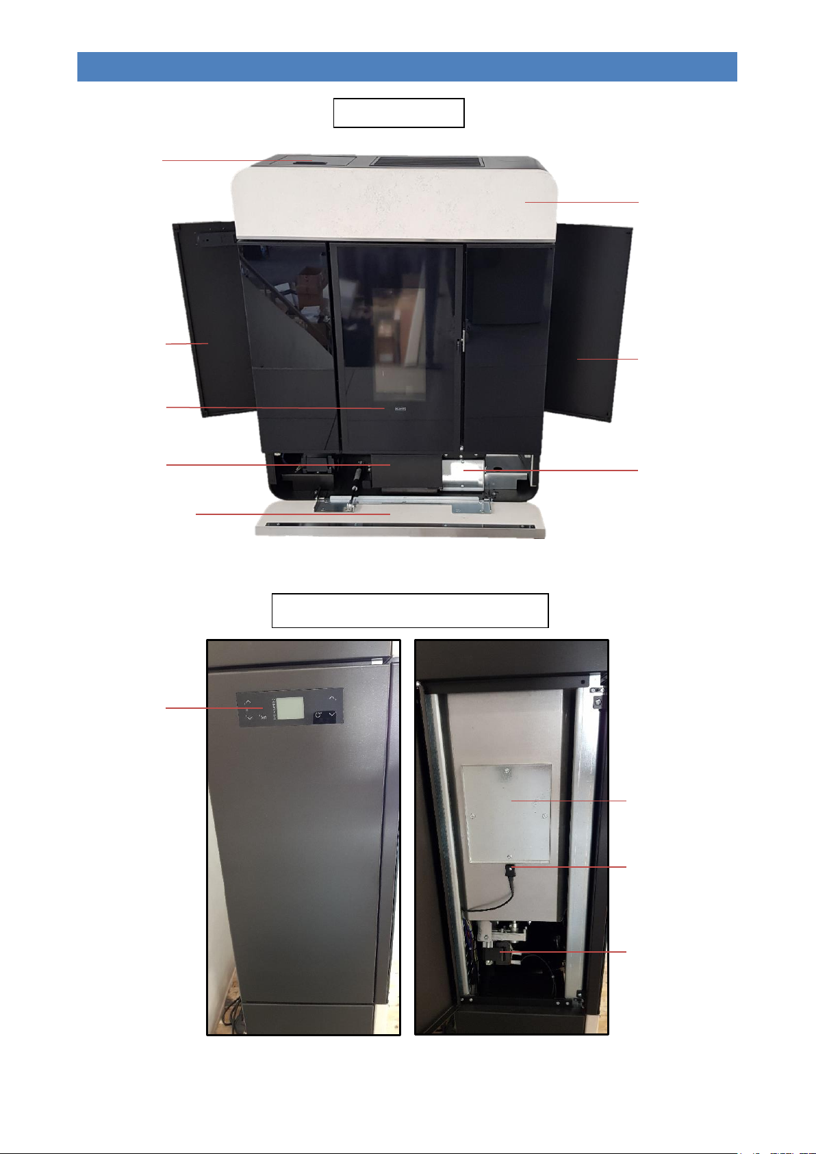
Pellet loading panel
Left-hand inspection
compartment
Combustion chamber
door
FRONT VIEW
LEFT-HAND INSPECTION COMPARTMENT
Right-hand inspection
compartment
(hydraulic circuit)
Ash tray door
Lower front inspection
compartment
(flue gas path and tray
cleaning)
TOUCH display
Tank inspection hatch
Pellet level
sensor
Gearmotor
Upper front
inspection
compartment
Flue gas path front
inspection plate
5
Page 9
DIVA SLIM PELLET BOILER STOVE
EN - Rev. 1.0
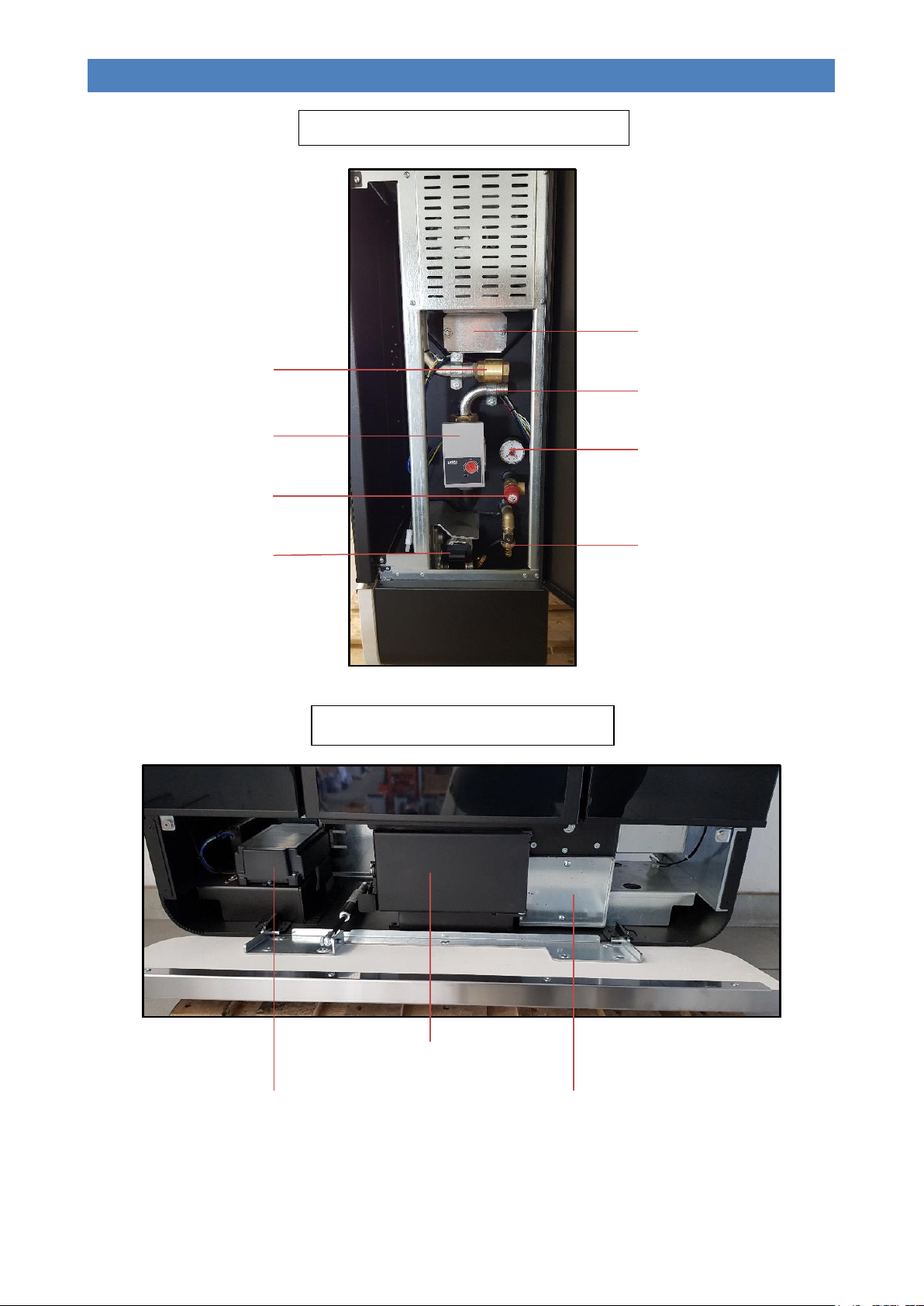
RIGHT-HAND INSPECTION COMPARTMENT
Flue gas path side
inspection plate
Delivery pipe
(YORK ¾" valve)
Return pipe
Pressure gauge
High-efficiency pump
Safety valve
(2.5 bar)
Boiler unit drain cock
Flue gas path
automatic cleaning
gearmotor
LOWER INSPECTION COMPARTMENT
Control unit
Ash tray inspection
panel
Flue gas path front
inspection plate
6
Page 10
DIVA SLIM PELLET BOILER STOVE
EN - Rev. 1.0
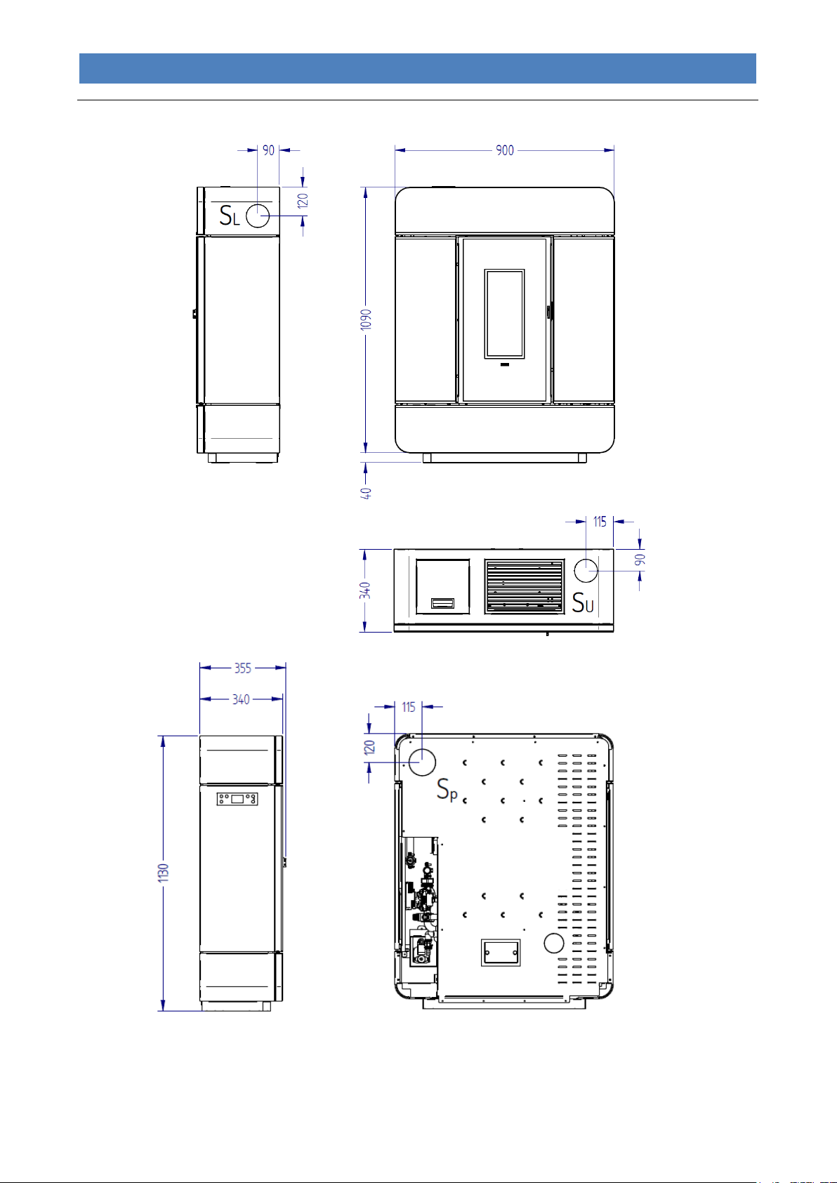
REAR VIEW
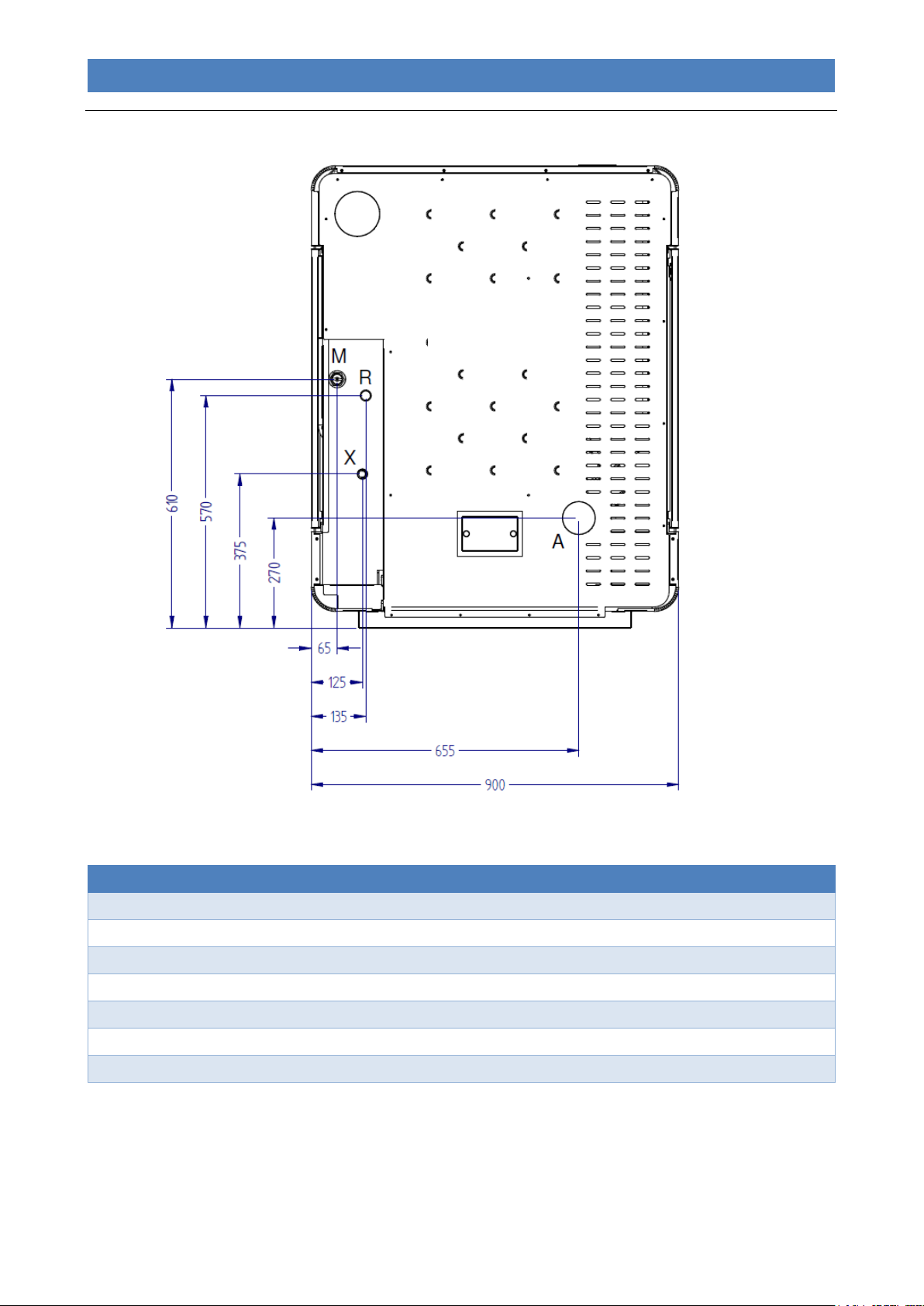
Overall dimensions
7
Page 11
DIVA SLIM PELLET BOILER STOVE
EN - Rev. 1.0
Description of connections
M = System Delivery
3/4" F
R = System Return
3/4" M
X = Safety valve drain
1/2" F
SL = Side flue gas outlet (refer to the “Overall dimensions” paragraph)
80 mm M
SU = Upper flue gas outlet (refer to the “Overall dimensions” paragraph)
80 mm M
SP = Rear flue gas outlet (refer to the “Overall dimensions” paragraph)
80 mm M
A = Rear fitting for connection of optional extraction pipe
40 mm
REAR VIEW
Connections data sheet
8
Page 12

DIVA SLIM PELLET BOILER STOVE
EN - Rev. 1.0
Heat input (nominal setting)
kW (Kcal/h)
19.8 (17,030)
Heat input (reduced setting)
kW (Kcal/h)
4.7 (4,050)
Nominal thermal output
kW (Kcal/h)
18.4 (15,830)
Reduced thermal power
kW (Kcal/h)
4.3 (3,700)
Nominal heat output ceded to water
kW (Kcal/h)
13.8 (11,900)
Nominal heat output ceded to the environment
kW (Kcal/h)
4.6 (3,950)
Reduced heat output ceded to water
kW (Kcal/h)
3.2 (2,750)
Reduced heat output ceded to the environment
kW (Kcal/h)
1.1 (950)
Combustion efficiency at nominal thermal power
%
93.1
Combustion efficiency at reduced thermal power
%
92.9
CO at 13% oxygen at nominal thermal power
%
0.003
CO at 13% oxygen at reduced thermal power
%
0.021
Maximum power uptake
Watt
400*
Power uptake during operation at nominal thermal power
Watt
40
Power uptake during operation at reduced thermal power
Watt
30
Power uptake in stand-by
Watt
2.0
Nominal voltage
V
230
Nominal frequency
Hz
50
Expansion vessel litres/preloading bar
6 / 1
Maximum operating/recommended pressure
bar
2.5 / 1.5
Flue outlet diameter
mm
80
Air intake pipe diameter
mm
40
Minimum chimney draught at nominal thermal power
Pa
10.5
Minimum chimney draught at reduced power
Pa
10.1
Combustion gas mass at nominal thermal power
g/s
11.0
Combustion gas mass at reduced power
g/s
4.8
Pellet tank capacity
Kg
25
Average exhaust flue gas temperature at nominal thermal power
°C
123.0
Average exhaust flue gas temperature at reduced power
°C
82.3
Boiler unit capacity
litres
20
Width
mm
900
Height
mm
1130
Depth
mm
340
Minimum safety distance from flammable materials
(side / rear / upper / front)
mm
200 / 200 / 750 / 800
Weight
Kg
225
Technical Specifications
* Power consumption only during the ignition cycle.
The appliance's heat output may vary depending on the type of pellets used.
9
Page 13
DIVA SLIM PELLET BOILER STOVE
EN - Rev. 1.0
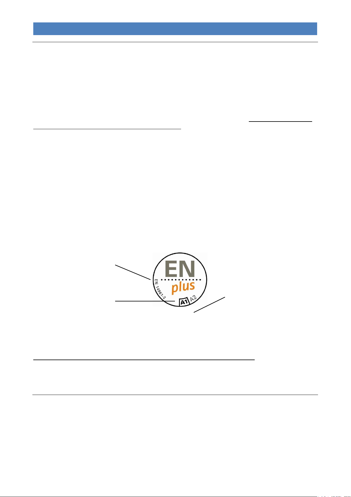
Indication of the standard,
base reference for the quality
classes ENplus
Indication of the quality
class of the certified pellet
(preferable A1)
IT xxx
Code of the certified company
consisting of two elements:
- Symbol of the country of
production (example “IT”)
- Progressive number assigned at
the acquisition of the
certification (example "xxx")
Pellet properties
The appliance has been tested with all types of pellets available on the market. The pellets must have the following
properties:
- Diameter 6 mm.
- Maximum length 35 mm.
- Maximum humidity content 8 – 9 %.
- 100% wood. Totally additive-free.
- Maximum ash residue 1.1 %.
To obtain good performance from the appliance, we recommend using good quality pellets. Pellets should be poured
into the tank using a shovel, and not directly from the bag.
Good quality pellets should have the following properties:
- Constant diameter cylinders with a smooth, shiny surface;
- There should not be a lot of sawdust inside the packaging;
- After grabbing a bunch of pellets and placing them into a container filled with water, good-quality pellets will sink and
poor-quality ones will tend to float;
- The quality certification data, in particular conformity to international standards such as EN14961-2, DIN 51731 and
O-NORM M7135, should be indicated on the packaging;
- The packages should be intact since pellets tend to absorb humidity. Humidity not only reduces the calorific value
and increases the amount of flue gases expelled, but also causes swelling of the product which may create problems
with the appliance.
The production of pellets must be compliant with some international standards (such as EN14961-2, DIN 51731 and ONORM M7135) which establish minimum values for quality checks on pellets. To facilitate the right choice of the
combustible material you can find below one of the most common certification marks identifying the quality of the pellets:
The use of poor quality pellets or any other material can damage the appliance operation, voiding the warranty
and exempting the manufacturer from all liability.
In order to guarantee trouble-free combustion, the pellets must be stored in a dry place.
REQUIREMENTS OF THE PLACE OF INSTALLATION
Positioning
The initial phase for best installation of the appliance is to determine its optimum location; the following elements need to
be considered:
- The possibility of creating an external air vent;
- The possibility of creating a straight flue, preferably coaxial to the outlet of the appliance;
- Proximity to the main water drain and/or the boiler (if one already exists);
- Proximity or ease of connection to the water system;
- Ease of access for cleaning the appliance, the flue gas exhaust pipes and the flue.
10
Page 14

DIVA SLIM PELLET BOILER STOVE
EN - Rev. 1.0
REAR VIEW
SIDE WALL
SIDE WALL
The unit must be installed on a floor with a suitable load capacity. If the existing building does not fulfil this requirement
appropriate measures (e.g. load distribution plate) must be taken.
The minimum safety distance from flammable materials must be at least 200 mm from the sides and back of the
appliance, 800 mm from the front and 750 mm from the upper part.
The installation must guarantee easy access for cleaning the appliance, the flue gas exhaust pipes and the flue, and any
subsequent maintenance operation by the Authorised technical assistance centre.
Once you have found the best location for the appliance, position it following the instructions given below.
The appliance must not be installed in small rooms, bedrooms, bathrooms or in areas with an explosive atmosphere
(e.g. garages).
Spaces around and above the appliance
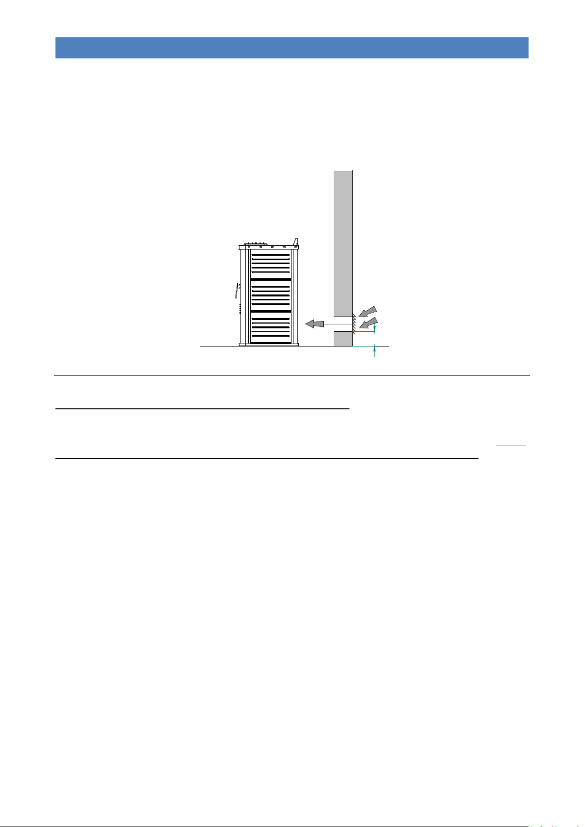
The figure below shows the minimum distances from walls or other not-easily-removable furniture, that need to be taken
into consideration when positioning the appliance.
Any shelves or false ceilings mounted above the appliance must be at least 75 cm away from the top part of it.
Furniture and movable objects made from flammable materials must be positioned at least 20 cm from the side surfaces
of the appliance; these objects must be moved when performing maintenance on the appliance.
Protect all structures that can catch fire against the radiated heat of the fire.
Any extra intervention by the Authorised technical assistance centre, which requires the appliance to be
disconnected from the system, will not be covered under warranty as described in the chapter “Standard
Warranty Conditions”.
External air intake
During operation, the appliance takes in air from the environment in which it is installed; It is therefore essential that this
air is replaced through an external air vent. The absence of the air vent may affect the flue draught and therefore the
combustion and the safety of the appliance.
Therefore it is mandatory to install an external air vent with a minimum completely free passage of at least 80 cm2
(round hole with minimum diameter of 15 cm protected with a special fixed large mesh grille).
If it not possible to put the external air vent in the same room as where the appliance is installed, this hole can be made
in an adjoining room as long as this room communicates permanently, by means of a transit hole (15 cm minimum
diameter).
The hole must be protected externally with a fixed grille. The protective grille must be checked periodically to ensure that
it is not obstructed, thereby impeding the passage of air. Therefore keep the air vents clear of obstructions.
The UNI 10683 Standard FORBIDS the drawing of combustion air from garages, warehouses storing combustible
materials, or from business premises with a fire hazard.
11
Page 15
DIVA SLIM PELLET BOILER STOVE
EN - Rev. 1.0
Fig. A
20
If there are other heating or extraction devices inside the room, the air vents must guarantee a sufficient amount of air for
properly operating all the devices.
Only sealed appliances (e.g. C type gas appliances, according to the UNI 7129 Standard) or appliances that do not
cause a lower pressure compared with the external environment can pre-exist or be installed in the place where the
appliance is installed.
Extractor fans can cause malfunctions to the appliance if used in the same room.
The flue and connection to the same
The flue is an essential element for the efficient operation of the appliance. The flue must have a minimum crosssectional area as that indicated in the technical specifications of the appliance (100 mm). Each product must be
equipped with its own flue, without other adjoining elements (boilers, chimneys, stoves, etc.). The flue dimensions are
closely related to its height, which must be measured from the appliance flue gas outlet to the base of the stack. In order
to guarantee adequate draught, the surface of the chimney flue outlet must be double the flue cross-section. The
discharge pipe for combustion products generated by the forced draught device, must comply with the following
requirements:
- It must seal off the combustion gases, as well as being waterproof and suitably isolated and insulated in relation to
the conditions of use (refer to UNI 9615);
- It must be made of suitable materials capable of withstanding normal mechanical stress, heat, and the effects of
combustion gases and condensate, if any;
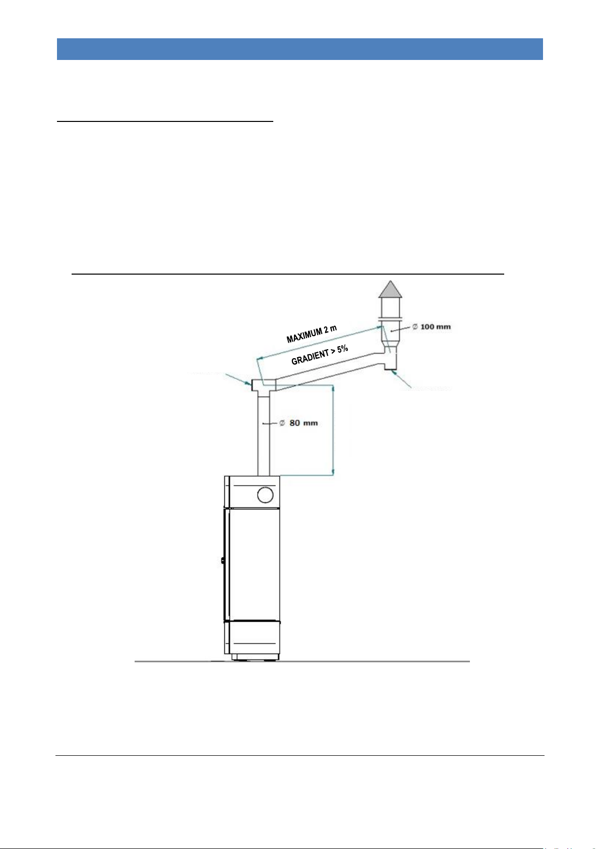
- It must go upwards after the vertical section, for the entire remaining part, with a minimum gradient of 5%. The sub-
horizontal section must not have a length greater than ¼ of the effective height H of the flue or chimney, and must
not be longer than 2,000 mm;
- It must preferably have a round internal cross-section: square or rectangular cross-sections must have rounded
corners with radius not inferior to 20 mm;
- It must have a constant, free and independent internal cross section;
- Rectangular cross-sections must have a maximum ratio of 1.5 between the sides;
- It must be insulated to prevent the fumes from cooling and forming condensation;
- Parts made from non-combustible materials (it is absolutely prohibited the use of aluminium flue) - capable of
withstanding combustion gases and potential condensation - must be used for mounting the flue gas pipes (for the
section from the appliance to the flue inlet);
- It is forbidden to use fibre cement pipes to connect the appliance to the flue;
- Flue gas conduits must not pass through rooms in which the installation of combustion devices is prohibited;
- The flue gas conduits must be assembled in such a way as to guarantee adequate sealing of flue gases during low
pressure operation of the appliance;
- The installation of horizontal sections is prohibited;
- It is prohibited to use counter sloping elements;
- The flue gas pipe must allow for the recovery of soot or be cleanable, and must have a constant cross-section;
12
Page 16
DIVA SLIM PELLET BOILER STOVE
EN - Rev. 1.0
INSPECTION HOLE
INSPECTION HOLE
MINIMUM 0.5 M
- It is forbidden to allow other air intake conduits and system pipes to transit inside the flue gas pipes, even if they are
over-sized.
FURTHER SPECIFICATIONS TO BE CONSIDERED
- The appliance works with the combustion chamber in depression and the flue pipe in pressure; it is essential that
the flue gas outlet is hermetically sealed.
- The flue pipes inside the installation room must be made of a suitable material (see current regulations) and
equipped with seal gaskets with a minimum diameter of 100 mm.
- The pipes must have a double wall (thermally insulated) or be suitably insulated with rock wool. The
maximum temperature of the flue pipe inside the room must not exceed 70°C.
- IT IS MANDATORY TO HAVE AN INITIAL VERTICAL SECTION OF AT LEAST 0.5 M IN ORDER TO
GUARANTEE CORRECT FLUE GAS DISCHARGE.
- Every direction change must be carried out with a T-shaped fitting and inspection cap. The tubes must be smoketight
thanks to special seals capable of withstanding temperatures of up to 250°C. Attach the pipes to the wall with special
collars to prevent any vibration.
- IT IS STRICTLY FORBIDDEN TO INSTALL DRAUGHT REGULATION VALVES (BUTTERFLY VALVES). WALL
If the flue is old or too large (internal diameter greater than 15 cm), it must be ducted using a stainless steel pipe that is
suitably insulated (with rock wool or vermiculite) and sized according to the route. The connection to the flue must be
appropriately sealed.
When assembling the flue, there must be no more than 4 direction changes.
Chimney
The chimney is a device crowning the flue, used to ease dispersion of combustion products.
13
Page 17
DIVA SLIM PELLET BOILER STOVE
EN - Rev. 1.0
Distance > 5 m
Distance < 5m
Distance > 1.85 m
Distance < 1.85 m
0.5 m
above the
highest
point
0.5 m
Technical
volume
0.5 m 1 m
minimum
Reflux
zone
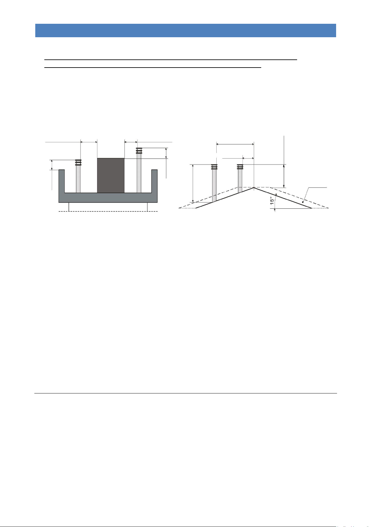
It must satisfy the following requirements:
- It must have a usable outlet cross-section no less than double that of the flue onto which it is inserted;
- It must be shaped in such a way as to prevent rainwater or snow from entering the flue;
- It must be built in such a way as to ensure the discharge of combustion by-products even in the event of winds from
every direction and inclination.
The outlet height (where height refers to the top of the flue, regardless of any chimney stacks) must be outside of the socalled reflux zone, in order to prevent the formation of counter-pressures preventing the free discharge of combustion
by-products into the atmosphere.
It is therefore necessary that the minimum heights - indicated in the following diagrams - are observed:
ELECTRICAL CONNECTION
The electric connection must only be performed by qualified staff, in compliance with all general and local safety
standards.
Check that the power supply voltage and frequency correspond to 230V – 50 Hz.
The appliance's safety is ensured when it is properly connected to an efficient earthing system.
In the electric connection to the mains power supply, include a 6 A – Id 30 mA differential trip-switch with suitable
breaking load. The electric connections, including the earth connection, must be made after shutting off the electrical
system.
When completing the system, bear in mind that the cables must be laid in an unmovable manner and far from parts
subject to high temperatures. During the final wiring of the circuit, only use components with a suitable electrical
protection rating. Do not pass electric cables in the immediate vicinity of the flue gas pipe, unless they are insulated with
suitable materials.
KLOVER srl declines all responsibility for injury to persons and animals or damage to objects due to failure to
connect the appliance to earth or to comply with IEC specifications.
Control of any coupled boiler
If the pellet appliance is to be coupled with a previously installed boiler in the system (e.g. wall-hung gas boiler), you
must ensure that the standard boiler stops when the pellet appliance takes over the heating of the system. The electrical
setting, which is accessible from the left-hand technical compartment, intervenes on the standard boiler when the
heating circulating pump of the pellet appliance starts up so as to avoid having two boilers operating simultaneously on
the same system. The coupled boiler is however always available for the production of domestic hot water.
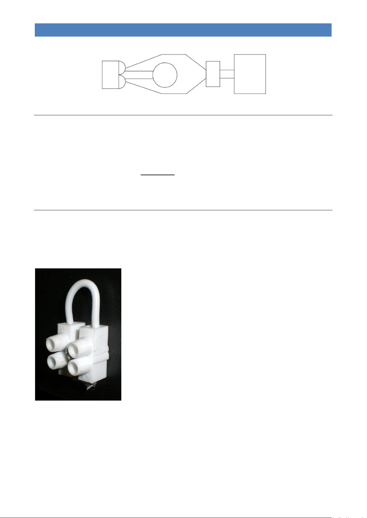
The two wires fitted on the left-hand technical compartment of the appliance (blue and brown wires) will have an
output voltage of 230 V when the pellet appliance pump is working, and no voltage when the pump stops.
It is therefore necessary to connect the 2 wires to a relay that will control the Room Thermostat (R.T.) input of the
coupled boiler (see the following example).
14
Page 18
DIVA SLIM PELLET BOILER STOVE
EN - Rev. 1.0
CN16
BROWN
PUMP
BLUE
T.A.
CONTACT
COUPLED
BOILER
Control of a possible three-way motorized valve for DHW system management
The pellet appliance is equipped as standard with a control for a possible 3-way motorised valve to be installed on the
domestic water circuit based on the selected system type (see “System configuration”). In the left-hand technical
compartment of the appliance there are four wires with fastons protected by a red seal, which can be used for controlling
the valve (see also “wiring diagram”). The four wires have different colours, and precisely:
- Blue wire = 3-WAY VALVE COMMON (Neutral 230 V)
- Black wire = SANITARY SIDE (Phase 230 V with DHW demand)
- Black wire = HEATING SIDE (Phase 230 V with no DHW demand)
- Yellow/green wire = GND
Connection to the room thermostat
On the left-hand technical compartment of the appliance there is a bridged terminal which is used to connect the room
thermostat that will command the operation. The operation of the room thermostat is enabled with system types 1, 2 and
3 (see“System configuration”).
OPERATING PRINCIPLE
If the above condition occurs during the switch-off cycle, please wait until the cycle is complete.
N.B.: If the water temperature exceeds the set threshold of 80°C (safety temperature), the circulating pump of the
system is forcedly switched-on to ensure the disposal of excessive heat, thus avoiding high water temperatures in the
boiler. For this reason it is recommended that the heating system is not entirely closed.
In the configuration “System type 3”, the appliance switches to economy mode and then switches off only if the “SET
BOILER” temperature setting has been reached.
Open contact:
- The appliance switches directly to economy mode operation “T-AMB ECONOMY”
thus minimising its operating power.
- The heating circulating pump of the appliance switches off.
- The temperature in the boiler increases due to thermal inertia until it reaches the
temperature set with “SET H2O” and displays “T-H2O ECONOMY” on its monitor.
- The appliance now switches itself off automatically if at least one of the following
conditions occurs:
- If it remains in Economy mode Operation “T-H2O ECONOMY” for a time
set on Pr44 (20 minutes as default setting).
- If it exceeds the temperature differential set on Pr43 (set as default at
5°C), in other words if Temperature H2O > (“SET H2O” + Pr43).
- The appliance will switch on again automatically if both of the following conditions
occur:
- The contact of the room thermostat closes.
- If it goes below the temperature differential of the “SET H2O”.
15
Page 19

DIVA SLIM PELLET BOILER STOVE
EN - Rev. 1.0
ATTENTION: In the event that the room sensor in the “Remote control” for the appliance is enabled, the appliance
switches to economy mode if the “SET ROOM” temperature setting has also been reached.
HYDRAULIC CONNECTION
The plumbing connections must be made in a rational way using the connections on the template of the appliance. To
facilitate connection of the pipes, all plumbing attachments have been fitted to the upper part of the appliance.
The appliance can be coupled with any other boiler already installed on the system. In this case it is essential to fit all the
necessary safety devices and shut-off valves based on the system and intended use. It is also necessary to consider all
laws and national, regional, provincial and municipal regulations of the country where the appliance is installed.
The appliance can be installed with the expansion vessel closed because it is equipped with a device for stopping fuel
loading, a safety manual reset thermostat and an audible alarm, which are activated if the temperature becomes too
high.
You can install the appliance in the same room as another boiler only if this has a sealed chamber; installation
must be performed in compliance with the current regulations.
When installing the appliance, it is advisable to fit an anti-condensate mixing valve between the delivery and
return pipes on the appliance’s heating system. The anti-condensate valve should be calibrated to 55°C with a
Kv value equal to or greater than 8 m3/h.
When connecting the appliance to the system, you should provide a zone that is always open (such as
bathroom area) to enable the excess heat dissipation of the water in the body of the boiler.
The maximum mains water pressure should never exceed 2.5 bar; recommended operating pressure is 1.5 bar
(with the appliance in operation).
In the event of water with hardness exceeding 28 °f, an anti-limescale device must be installed. This must be
selected on the basis of the specific properties of the water.
TO AVOID COMPROMISING THE OPERATION AND LIFE OF THE HEAT PUMP, INSTALLATION OF A FILTER
AND A MAGNETIC DIRT SEPARATOR IS RECOMMENDED DOWNSTREAM OF THE RETURN PIPE ON THE
APPLIANCE.
The appliance must be mounted exclusively by qualified personnel. Scrupulously comply with the instructions given
in this guide.
The manufacturer declines any liability for damages caused due to incorrect assembly.
16
Page 20
DIVA SLIM PELLET BOILER STOVE
EN - Rev. 1.0
Set
1
2 5
6
3 4
Set
1
2 5
6
3 4
WATER TEMPERATURE
CLOCK
ROOM TEMPERATURE (optional)
17:19
- - - - 60°C
WORK 3
2
DIALOGUE
REAL WORK POWER
(It is shown flashing only when it is different
from the one actually set)
2nd LED SERIES
1st LED SERIES
THE DISPLAY
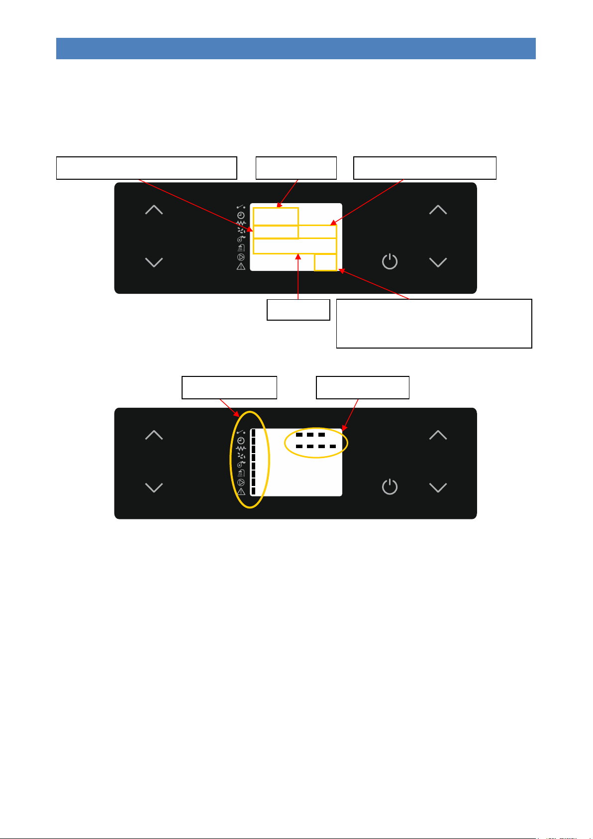
The appliance's operating mode is displayed on the console. After turning on the menu, it is possible to choose from
many types of display and available settings according to the selected menu.
The figures below show the display when the appliance is in ON mode.
17
Page 21
DIVA SLIM PELLET BOILER STOVE
EN - Rev. 1.0
Set
1
2 5
6
3 4
!
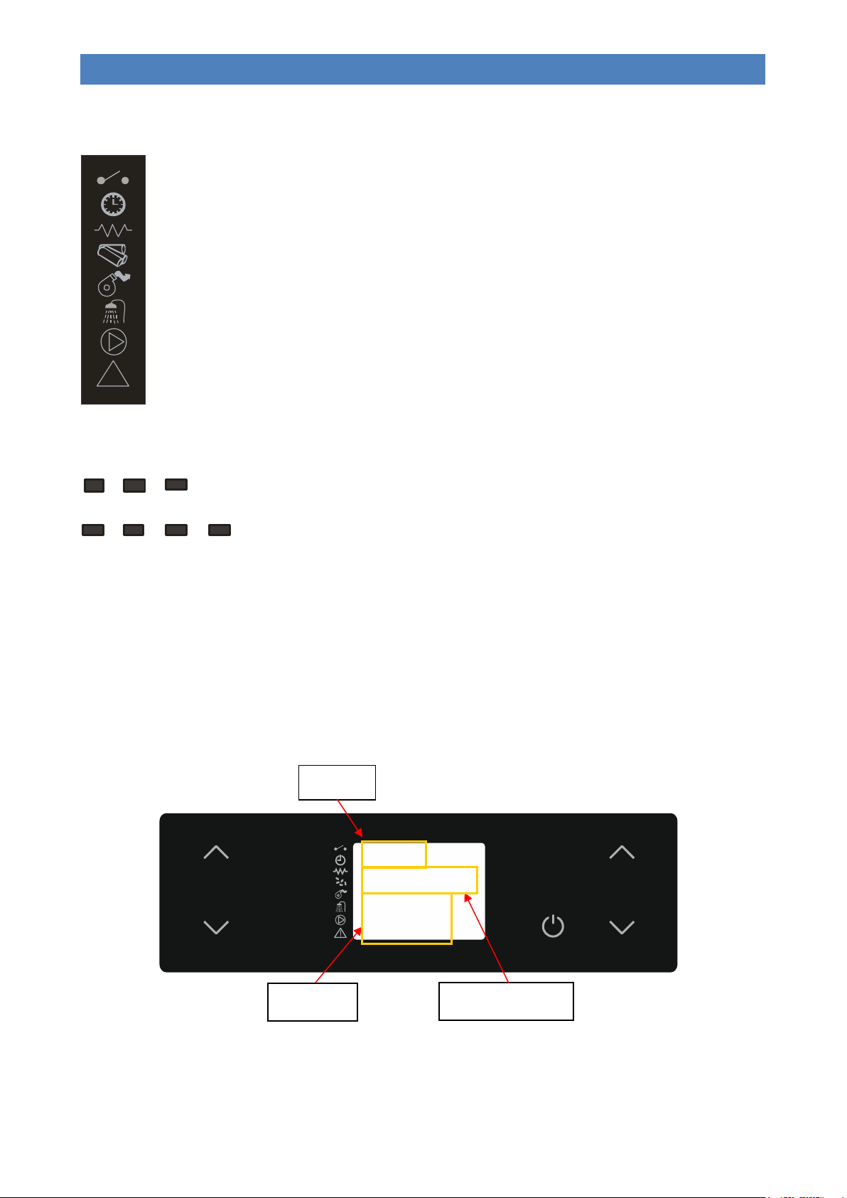
ROOM THERMOSTAT: the LED is on when the thermostat contact is open.
PROGRAMMABLE THERMOSTAT: the LED lights up when at least one start-up and switch-off program is active.
IGNITION PLUG: the LED is on when the ignition plug is active.
SCREW FEED: the LED lights up when the pellet loading gear motor is started.
FLUE GAS EXTRACTOR: the LED lights up when the flue gas extractor is active.
DHW DEMAND: the LED lights up when the DHW flow switch contact is closed (which means there is demand for
hot water) or the DHW cylinder or puffer (where fitted) is in demand.
PUMP: the LED lights up when the system circulation pump is active.
ALARM: the LED lights up when the boiler is in a state of alarm.
1
2 3 4 5 6
7
INPUT
DIALOGUE
MENU LEVEL
On
M - 2 - 2 - 01
TIMER
DAY
The following figure describes the meanings of the status signals appearing on the left side of the display (1st LED
SERIES).
The meanings of the status signals appearing on the top right side of the display are described below (2nd LED
SERIES).
- LED 1: the LED lights up when the daily programme of the on off settings is active.
- LED 2: the LED lights up when the weekly programme of the on off settings is active.
- LED 3: the LED lights up when the weekend programme of the on off settings is active.
- LED 4: the LED lights up (flashing) when the operation parameters are being edited.
- LED 5: the LED lights up when the summer function is active.
- LED 6: the LED lights up when the winter function is active.
- LED 7: the LED is not currently used.
The following diagram shows the display when setting or programming operating parameters.
The INPUT area shows the entered programming values.
The MENU LEVEL area shows the current parameter/menu level.
The DIALOGUE area displays the meaning of the current parameter/menu.
18
Page 22

DIVA SLIM PELLET BOILER STOVE
EN - Rev. 1.0
KEY
DESCRIPTION
MODE
ACTION
1
Increase temperature (1)
Programming mode..
Changes/increases the value of the selected menu
item.
Working/off..
It increases the temperature of the room/water
thermostat.
2
Decrease temperature (2)
Programming mode..
Changes/decreases the value of the selected menu
item.
Working/off..
It decreases the temperature of the room/water
thermostat.
3
Set
-
Enters the menu in question.
Menu mode..
Accesses the next level of sub-menus.
4
ON/OFF
Outlet
Working..
Switches the appliance on and/or off when pressed
for 2 seconds.
In alarm block..
Releases the alarm.
Menu/programming mode..
Moves you to the previous menu level, saving the
changes made.
5
Decrease power (3)
Working/off..
Decreases the working/fan power of the appliance.
Menu mode..
Moves you to the next menu item.
Programming mode..
Moves you to the next submenu item, storing the
changes made.
6
Increase power (3)
Working/off..
Increases the working/fan power of the appliance.
Menu mode..
Moves you to the previous menu item.
Programming mode..
Moves you to the previous submenu item, storing
the changes made.
The table explains how the buttons on the display work.
(1) The first press selects “Set temperature for boiler water - SET H2O” or “Set DHW boiler temperature - SET BOILER”
or “Set centralised puffer temperature - SET PUFFER” based on the system configuration type.
(2) It selects “Set temperature for boiler water - SET H2O” when first pressed.
(3) It selects the operating power “SET POWER” when first pressed.
THE MENU
Access the Menu by pressing key 3 (Set).
The menu is divided into different items and levels, providing access to the programming and settings options of the
appliance.
Buttons 5 and 6 allow you to select the menus to be modified.
Buttons 1 and 2 allow you to change the set value in the selected menu.
Listed below are the menus present on the PCB, with the relevant explanations.
Menu 01 – Choose season
Allows you to set the season for appliance use (SUMMER / WINTER). Can only be used with plumbing system 3 (see
“System configuration”).
19
Page 23

DIVA SLIM PELLET BOILER STOVE
EN - Rev. 1.0
MENU LEVEL
SELECTION
MEANING
POSSIBLE VALUES
03 – 01 – 01
ENABLE CHRONO
Enable/disable set programs
ON – OFF
MENU LEVEL
SELECTION
MEANING
POSSIBLE VALUES
03 – 02 – 01
CHRONO DAY
Enable/disable the daily programme
ON – OFF
03 – 02 – 02
START 1 DAY
Turn-on time of the first programme
Time – OFF
03 – 02 – 03
STOP 1 DAY
Turn-off time of the first programme
Time – OFF
03 – 02 – 04
START 2 DAY
Turn-on time of the second programme
Time – OFF
03 – 02 – 05
STOP 2 DAY
Turn-off time of the second programme
Time – OFF
MENU LEVEL
SELECTION
MEANING
POSSIBLE VALUES
03 – 03 – 01
CHRONO WEEKLY
Enable/disable the weekly programme
ON – OFF
PROGRAMME 1
MENU LEVEL
SELECTION
MEANING
POSSIBLE VALUES
03 – 03 – 02
START PROG 1
Turn-on time of the first programme
Time – OFF
03 – 03 – 03
STOP PROG 1
Turn-off time of the first programme
Time – OFF
03 – 03 – 04
MONDAY PROG 1
Reference days of the first programme
On/off
03 – 03 – 05
TUESDAY PROG 1
On/off
03 – 03 – 06
WEDNESDAY PROG 1
On/off
03 – 03 – 07
THURSDAY PROG 1
On/off
03 – 03 – 08
FRIDAY PROG 1
On/off
03 – 03 – 09
SATURDAY PROG 1
On/off
03 – 03 – 10
SUNDAY PROG 1
On/off
Menu 02 – Set clock
Allows for setting the current date and time.
Menu 03 – Set timer
Sub-menu 03 – 01 – enable timer
Allows you to globally enable and disable all programmable thermostat functions. For the correct operation it is
recommended to enable it (“ON”) when at least one on/off programme (daily, weekly or weekend programme) is
activated.
Submenu 03 – 02 – daily program
Allows you to enable, disable and set the programmable thermostat daily programme functions.
Two operating time slots can be set according to the following table, where OFF signals the clock to ignore the
command:
Sub-menu 03 – 03 – weekly program
Allows you to enable, disable and set the programmable thermostat weekly program functions.
The weekly programmer has 4 independent on/off programmes; it is not essential to use all four simultaneously.
By setting OFF in the time field, the clock ignores the corresponding command.
20
Page 24
DIVA SLIM PELLET BOILER STOVE
EN - Rev. 1.0
PROGRAMME 2
MENU LEVEL
SELECTION
MEANING
POSSIBLE VALUES
03 – 03 – 11
START PROG 2
Turn-on time of the second programme
Time – OFF
03 – 03 – 12
STOP PROG 2
Turn-off time of the second programme
Time – OFF
03 – 03 – 13
MONDAY PROG 2
Reference days of the second programme
On/off
03 – 03 – 14
TUESDAY PROG 2
On/off
03 – 03 – 15
WEDNESDAY PROG 2
On/off
03 – 03 – 16
THURSDAY PROG 2
On/off
03 – 03 – 17
FRIDAY PROG 2
On/off
03 – 03 – 18
SATURDAY PROG 2
On/off
03 – 03 – 19
SUNDAY PROG 2
On/off
PROGRAMME 3
MENU LEVEL
SELECTION
MEANING
POSSIBLE VALUES
03 – 03 – 20
START PROG 3
Turn-on time of the third programme
Time – OFF
03 – 03 – 21
STOP PROG 3
Turn-off time of the third programme
Time – OFF
03 – 03 – 22
MONDAY PROG 3
Reference days of the third programme
On/off
03 – 03 – 23
TUESDAY PROG 3
On/off
03 – 03 – 24
WEDNESDAY PROG 3
On/off
03 – 03 – 25
THURSDAY PROG 3
On/off
03 – 03 – 26
FRIDAY PROG 3
On/off
03 – 03 – 27
SATURDAY PROG 3
On/off
03 – 03 – 28
SUNDAY PROG 3
On/off
PROGRAMME 4
MENU LEVEL
SELECTION
MEANING
POSSIBLE VALUES
03 – 03 – 29
START PROG 4
Turn-on time of the fourth programme
Time – OFF
03 – 03 – 30
STOP PROG 4
Turn-off time of the fourth programme
Time – OFF
03 – 03 – 31
MONDAY PROG 4
Reference days of the fourth programme
On/off
03 – 03 – 32
TUESDAY PROG 4
On/off
03 – 03 – 33
WEDNESDAY PROG 4
On/off
03 – 03 – 34
THURSDAY PROG 4
On/off
03 – 03 – 35
FRIDAY PROG 4
On/off
03 – 03 – 36
SATURDAY PROG 4
On/off
03 – 03 – 37
SUNDAY PROG 4
On/off
MENU LEVEL
SELECTION
MEANING
POSSIBLE VALUES
03 – 04 – 01
CHRONO WEEK-END
Enable/disable the weekend programme
ON – OFF
03 – 04 – 02
START 1st WEEKEND
Turn-on time of the first programme
Time – OFF
03 – 04 – 03
STOP 1st WEEKEND
Turn-off time of the first programme
Time – OFF
03 – 04 – 04
START 2nd WEEKEND
Turn-on time of the second programme
Time – OFF
03 – 04 – 05
STOP 2nd WEEKEND
Turn-off time of the second programme
Time – OFF
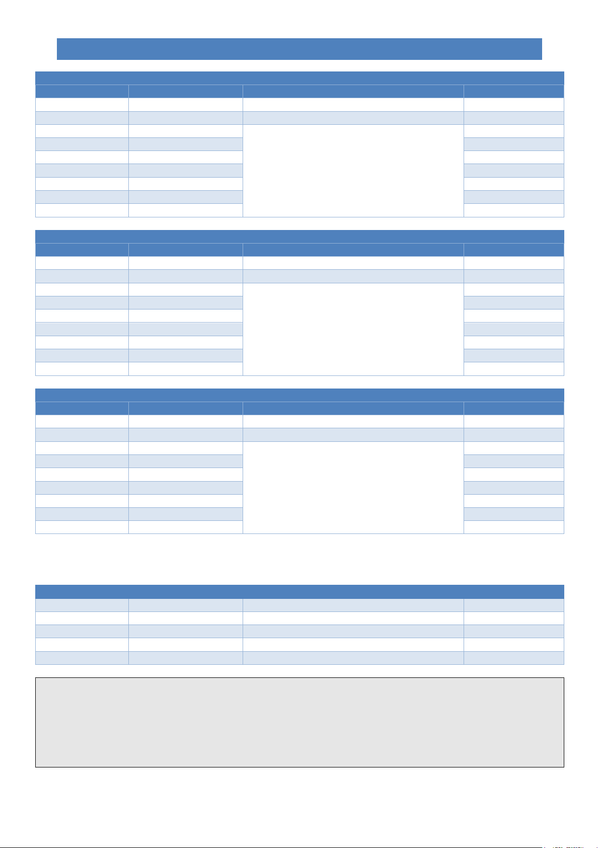
TIP: in order to avoid confusion and any undesired switching on/off operations, only activate a single programme at a time (daily,
weekly or weekend programme).
Deactivate the daily program if you wish to use the weekly program instead. If you use the weekly program in programs 1, 2, 3
and 4, always keep the week-end program disabled.
Only enable week-end programming after disabling the weekly program.
Sub-menu 03 – 04 – week-end program
Enables/disables/sets the programmable timer's weekend functions (Saturday and Sunday).
21
Page 25

DIVA SLIM PELLET BOILER STOVE
EN - Rev. 1.0
Menu 04 – Choose language
Allows you to select the dialogue language from the available choices (Italian, English, French, German and Spanish).
Menu 05 – Acoustic alarm
Allows you to enable or disable the acoustic signal in the event of an alarm. The alarm signal is only available on the
appliance board, and not on the external “Remote control”.
Menu 06 – Initial load
Enables pellet pre-loading for 180” when the appliance is switched off and cooled down. Start the function with button 1
and stop with button 4. This may be useful if the appliance is switched on after the tank has been completely emptied, or
when it is filled for the first time. Warning: once the operation has been completed, before switching on the
appliance you should empty the accumulation of pellets deposited inside the brazier.
Menu 07 – Fireplace status
It allows for viewing the instantaneous state of the appliance, by showing the state of the various devices connected to it.
Several pages are displayed in succession. The data is reserved for Technical assistance Centre.
Menu 08 – Technical calibration
Allows you to access all data reserved for the Technical Assistance Centre. Access is protected by a password.
Unauthorised access can cause serious damage to the equipment, to things and the environment as well as personal
injuries.
Menu 09 – System type
Allows you to configure the appliance according to the type of system is has been connected to (see “System
configuration”).
INITIAL START-UP
System configuration
Before commissioning the appliance it is advisable to choose which type of system it has been connected to, by
accessing “Menu 06 – System type”.
The available configurations are given here below:
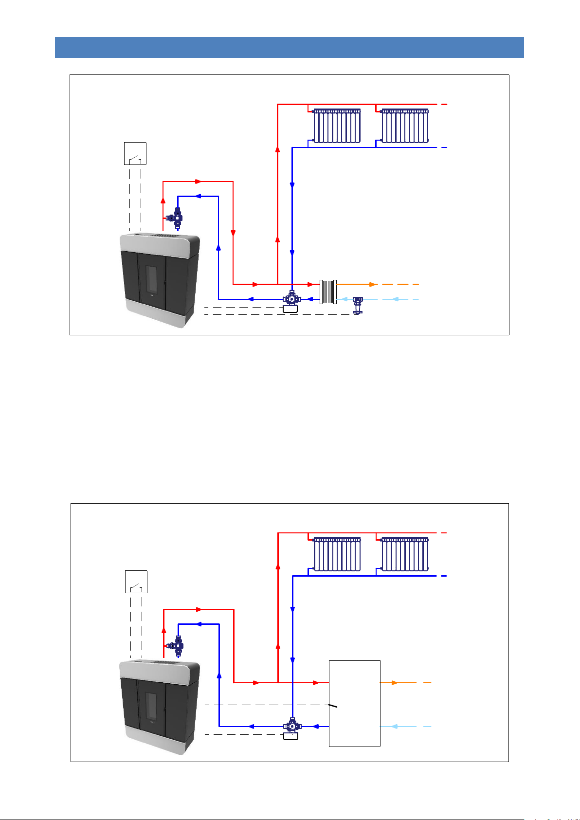
PLUMBING LAYOUT “1” – Boiler stove connected to a heating system and (potentially) an external plate heat
exchanger for the production of DHW.
22
Page 26
DIVA SLIM PELLET BOILER STOVE
EN - Rev. 1.0
T.A.
AB B
A
Bollitore
accumulo
ACS
T.A.
A
B
AB
DHW
cylinder
Plumbing layout 1 involves connecting the boiler stove to a heating system (or centralised puffer) managed by one or
more room thermostats. These are connected to the terminal located inside the appliance’s left technical compartment.
DHW generation, where required, will be obtained through a plate heat exchanger fitted outside of the boiler stove and
controlled by a flow switch, which is also connected to a terminal on the boiler stove. This function of this switch is to
bring the appliance immediately to the DHW output working mode and to switch a three-way motor-driven valve to give it
priority.
PLUMBING LAYOUT “2” – Not used
PLUMBING LAYOUT “3” – Boiler stove connected to a heating system and a DHW cylinder.
23
Page 27
DIVA SLIM PELLET BOILER STOVE
EN - Rev. 1.0
Puffer
centr alizzato
Centralised
puffer
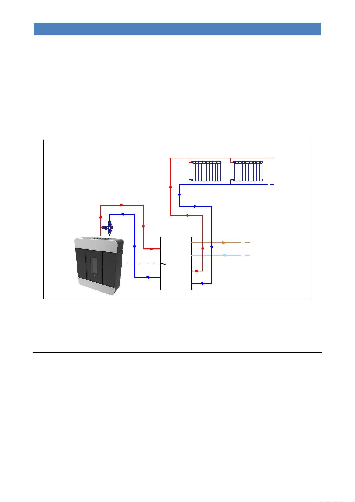
Plumbing layout 3 involves connecting the boiler stove to a heating system managed by one or more room thermostats.
These are connected to the terminal located inside the appliance’s left technical compartment. DHW will be generated by
means of a hot water cylinder fitted outside of the boiler and controlled by a temperature probe connected to the
appliance.
The three-way motor-driven valve, controlled by the pellet boiler stove, will manage heating of the system or hot water
cylinder, giving priority to the latter.
Setting “Menu 01 – Select season” to SUMMER allows for controlling the hot water cylinder only during summer (thus
with the heating system off).
PLUMBING LAYOUT “4” – Boiler stove connected to a centralised puffer controlled by an H2O probe connected to the
boiler stove.
Plumbing layout 4 involves connecting the boiler to a centralised puffer controlled by a temperature probe connected to
the appliance. The boiler stove will therefore operate only at the set temperature of the centralised puffer (“SET
PUFFER” can be set using buttons 1 and 2). In this type of system there are no room thermostats or three-way valves
connected to the pellet boiler stove.
Initial filling of the system
After the water connection of the appliance, fill the system as follows:
- Check the seal of all piping, the expansion vessel, and the circulation pump;
- Open the “automatic air release valve” on the appliance;
- Open the system load cock (mounted on the appliance) to load the system. Gradually allow the air to come out from
the appliance through the “automatic air release valve”; optimum working pressure is 1.5 bar (when the
appliance is operating);
- Vent all radiators and any other de-aeration systems to ensure that there are no air bubbles in the system.
After installation, check the seal of all plumbing joints for the first few days of operation.
The system and the water inside the boiler can be emptied by opening the “boiler body and system drain cock” situated
on the right side of the appliance.
24
Page 28

DIVA SLIM PELLET BOILER STOVE
EN - Rev. 1.0
In intensely cold periods it is good practice to leave the heating system running. In the event of a prolonged
absence, anti-freeze must be added to the heating water or the system must be completely emptied.
In a system subject to being emptied frequently, it is essential that filling is performed with water suitably treated to
remove hardness which can give rise to scaling.
Pellet loading and connection to the mains power supply
Perform the following operations:
- Connect the appliance to the electrical system by using the provided cable;
- Set the “power ON/OFF switch” on the front of the appliance to “׀” (on);
- Fill the pellet tank; for the first ever ignition, to avoid wasting the time required for filling the entire screw feed channel
(this should be done every time the appliance runs out of pellets), we recommend you follow the instructions in
the “Menu 08 – Initial load”;
- Switch the appliance on by using the ignition button on the display (button 4). See the instructions below. Warning:
before switching on the device make sure that there are no pellets in the brazier; otherwise it is necessary to
empty and clean the brazier.
We recommend that you use high quality pellets so as not to impair the operation of the appliance. Damage
caused by poor-quality pellets shall not be covered by the warranty.
Do not pour pellets directly into the brazier.
Ignition cycle
Pressing button 4 (ON/OFF) for a few seconds allows you to start the ignition cycle. After a few seconds, “START” will
appear on the display and the flue gas extractor, ignition plug and motor for the automatic cleaning of the flue gas path
will all switch on. After a few seconds, the appliance enters a pre-load phase “PELLET P-LOAD” during which a
continuous supply of pellets is loaded. After the pre-loading phase the appliance switches to the “HOLD FLAME” phase
where the pellets are loaded into the brazier at regular intervals. When the flame is lit, the display shows the message
“FIRE ON”. This step is used to allow the fire to spread evenly across the brazier and burn all the unburned pellets from
the previous phases. After these phases, the appliance enters the work mode at the pre-set power value.
If the ignition fails, the display will show the alarm “NO IGNIT ALARM”. The alarm may also occur if the brazier is
dirty; in this case, clean the brazier and re-start.
Summary:
The ignition cycle can last 20/25 minutes max. and is divided into five steps:
Step 1 - START = Ignition of the flue gas extractor.
Step 2 - WAITING PREHEATING = Waiting for the plug preheating. (Not as standard settings).
Step 3 - PELLET P-LOAD = Pellet pre-load (initial continuous load) and plug ignition.
Step 4 - HOLD FLAME = Loading pellets (intermittent load) and plug operating.
Step 5 - FIRE ON = Plug switch-off and flame stabilisation.
The appliance switches into working mode after ignition phase at the power output set during ignition via buttons 1 and
2.
Warning: during the ignition phase and normal operation of the appliance, maintain the necessary safety
distance and do not stand in front of it.
Switch-off cycle
The appliance switches off if you press button 4 (ON/OFF) during normal operation. The display will show “FINAL
CLEANING”. The pellet loading stops and the flue gas extractor speed increases to maximum and then switches off after
the cooling of the appliance, displaying "OFF”.
25
Page 29
DIVA SLIM PELLET BOILER STOVE
EN - Rev. 1.0
Set
1
2 5
6
3 4
Set
1
2 5
6
3 4
Set
1
2 5
6
3 4
65°C
SET
BOILER
3
SET
POWER
70°C
SET
H2O
If button 4 (ON/OFF) is pressed during the ignition cycle, the appliance switches to “WAITING OFF” and the appliance
will be turned off only at the end of the entire cycle; if, however, button 4 (ON/OFF) is pressed by mistake during this
phase, you only need to press it again to delete “WAITING OFF”: the appliance will return to normal operation at the end
of the entire ignition cycle.
Modifying the working power
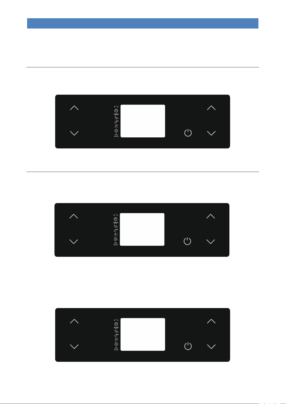
To modify the maximum working power you must select “SET POWER” by pressing buttons 5 or 6. Press buttons 5 and
6 to change the setting. During this operation, the display will appear as in the following picture.
After setting the desired value, press button 4 or wait a few seconds to confirm.
Changing the water temperature boiler or puffer
- Boiler Water Temperature
For system types 1, 2 and 3, to modify the boiler water temperature, simply select “SET H2O” by pressing button 2. Now
use buttons 1 and 2. During this operation, the display will appear as in the following picture.
After setting the desired value, press button 4 or wait a few seconds to confirm.
During the working mode the appliance enters “Economy mode operation” when that temperature value is reached.
- DHW cylinder temperature
For system type 3, to modify the boiler temperature, simply select “SET BOILER” by pressing button 1. Now use buttons
1 and 2. During this operation, the display will appear as in the following picture.
After setting the desired value, press button 4 or wait a few seconds.
26
Page 30
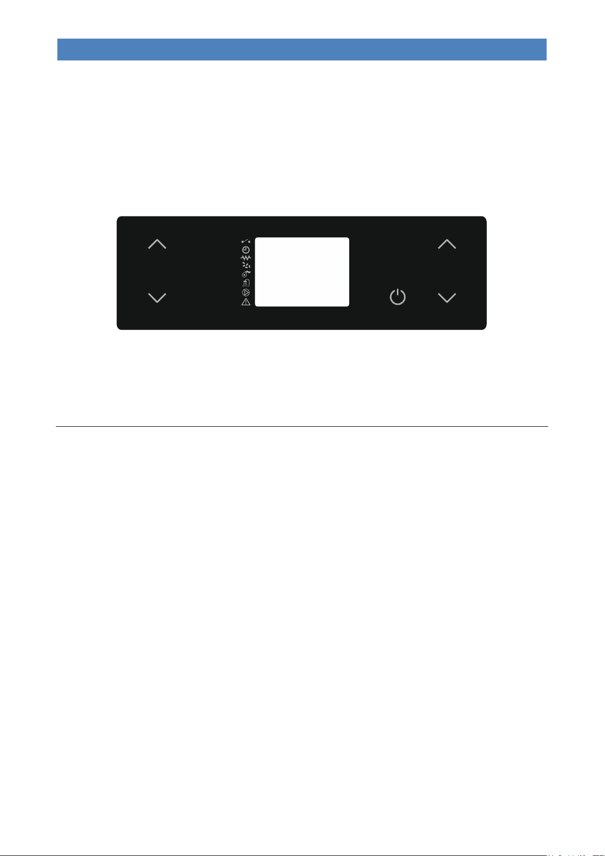
DIVA SLIM PELLET BOILER STOVE
EN - Rev. 1.0
Set
1
2 5
6
3 4
65°C
SET
PUFFER
During the working phase, if the boiler is in demand the appliance will switch to “Economy mode” if T.H2O > SET
BOILER + 10°C.
Here below are the operating modes in the event that the “SET BOILER” temperature is reached:
- “Menu 01 – Select season = SUMMER” the appliance will immediately go into stand-by “STOP FIRE”.
- “Menu 01 – Select season = WINTER” the motorised three-way valve and the appliance will go into stand-by “STOP
FIRE” only if the conditions in the heating system are satisfied.
- Puffer temperature
For system type 4, to modify the puffer temperature, simply select “SET PUFFER” by pressing buttons 1 or 2. Now use
buttons 1 and 2. During this operation, the display will appear as in the following picture.
After setting the desired value, press button 4 or wait a few seconds.
During the working phase the appliance will switch to “Economy mode” if T.H2O > SET PUFFER + 10°C.
The appliance will enter the “STOP FIRE” stand-by mode only if the “SET PUFFER” temperature is reached.
PROBLEMS, ALARMS, USEFUL TIPS
Useful info…
Listed below is some important information regarding the appliance:
- It is normal for the appliance to emit a smell of paint during its first few days of operation. We recommend properly
ventilating the installation room during the initial start-up. For the first few days of operation we also recommend that
you set the appliance to near-maximum level.
- The boiler unit is treated with anti-oxidant paint in order to protect it against oxidation in the event of long periods of
inactivity. After initial start-up, this paint no longer preserves its original features and any wear of the paint inside the
combustion chamber should not be regarded as a manufacturing fault.
- Do not clean with water inside the combustion chamber; any oxidation of the combustion chamber after a long period
of inactivity is not to be considered as a manufacturing fault.
- Any perceived noise during operation may be caused by the expansion settling of the plates that make up the boiler
unit. These noises are accentuated especially during ignition and switching off phases of the appliance and are not to
be considered a manufacturing fault.
- If ignition fails, empty the pellets out of the brazier; only then can you reignite the appliance in order to avoid
gasification and consequent “explosion” during ignition which could lead to the breakage of the door glass.
- The appliance works exclusively with wooden pellets; do not burn different fuels.
- The appliance can work only if connected to the heating system and with water inside the boiler unit. Do not start the
appliance for any reason if a plumbing connection in compliance with current regulations has not been done and if
you have not filled the entire boiler unit and system with water in order not to compromise its life.
- The noise heard during the ignition stage is due to the automatic cleaning of the turbulators.
- The noise level of the appliance is emphasised if the pellet container is empty. Therefore we recommend that you
always keep the pellet level to at least half tank.
- If there is soot and fine particulate in the room where the appliance is installed, check the seal on the flue gas pipes
and the filter of the ash vacuum device used for cleaning.
- In the event of overheating, the appliance will switch off when it reaches 85°C.
27
Page 31

DIVA SLIM PELLET BOILER STOVE
EN - Rev. 1.0
Previous state
Black-out duration
State after power restore
OFF
any
OFF
START
duration < Pr48
START
START
duration > Pr48
START
P-LOAD PELLET
any
BLACK OUT ALARM
HOLD FLAME
any
BLACK OUT ALARM
FIRE ON
duration < Pr48
FIRE ON
FIRE ON
duration > Pr48
STOP FIRE with automatic re-ignition after machine cooling
WORK (any phase)
duration < Pr48
WORK (any phase)
WORK (any phase)
duration > Pr48
STOP FIRE with automatic re-ignition after machine cooling
BRAZIER CLEANING
duration < Pr48
BRAZIER CLEANING
BRAZIER CLEANING
duration > Pr48
STOP FIRE with automatic re-ignition after machine cooling
FINAL CLEANING
duration < Pr48
FINAL CLEANING and after cooling OFF
FINAL CLEANING
duration > Pr48
FINAL CLEANING and after cooling OFF
STOP FIRE
any
STOP FIRE
What happens if…
…the pellets do not ignite
If the ignition fails, the display will show the alarm message “NO IGNIT ALARM”.
Cancel the alarm and reset the appliance to standard condition by pressing button 4 for a few seconds.
If ignition fails, empty the pellets out of the brazier; to avoid gasification, the appliance can only be re-ignited
after having emptied the un-burnt pellets.
...the fire door or the pellet container door is open or not properly closed
If the door is left open or not properly closed, the pellet loading will not start, therefore the appliance will not switch itself
on. If the door is opened during normal operation, the appliance switches to “THERMAL SAFETY” alarm.
...the flue pipe is dirty, blocked or not correctly installed
If the flue is dirty, blocked or incorrectly manufactured, pellet loading will not start, thus the appliance will not switch itself
on. If the flue is obstructed during normal operation, the appliance switches to “DEPRESS.-FAILURE” alarm.
...the appliance is overheated
If the water in the boiler body is overheated (>94°C), the pellet will not be loaded because the manual reset thermostat
cuts in. If this happens during normal operation, the appliance switches to “THERMAL SAFETY” alarm. It is therefore
necessary to reset the “manual reset thermostat” (see “Components of the appliance”) before switching the appliance on
again. To reset, it is necessary to remove the black cap and press the button below.
...lack of power (blackout)
If a power blackout occurs for a shorter time than Pr48, when power is restored, the appliance will immediately re-start in
the working mode (recovering the set working power).
If the outage lasts longer than Pr48, when power is restored, the appliance will enter the “STOP FIRE” (stand-by) mode
running the entire switch-off cycle until cooling. When this phase is over, the appliance can be restarted resuming work
at the set power.
28
Page 32

DIVA SLIM PELLET BOILER STOVE
EN - Rev. 1.0
DISPLAY VISUALISATION
ORIGIN OF ALARM
AL 1 - BLACK OUT ACTIVE ALARM
Black-out alarm. When power is cut off under determined conditions (see“What
happens if…”)
AL 2 - FLUE GAS PROBE ACTIVE ALARM
Faulty or disconnected flue gas temperature probe.
AL 3 - HOT TEMP ACTIVE ALARM
Flue gas over-temperature. Before displaying the alarm, or when flue gas
maximum temperature is reached (Pr14). the display shows “HOT FLUE
GAS”.
AL 4 - EXTRACTOR-FAILURE ACTIVE ALARM
Faulty flue gas extractor. When the encoder (tachometer) in the extractor
detects an extractor speed equal to 0.
AL 5 - NO IGNITION ACTIVE ALARM
No ignition. When the flue gas minimum temperature (Pr13) is not reached
within the maximum ignition cycle time (Pr01).
AL 6 - NO PELLET ACTIVE ALARM
Sudden shut-down during the work phase. When, during the work phase, the
flue gas temperature drops below the minimum threshold (Pr28).
AL 7 - THERMAL-SAFETY ACTIVE ALARM
Temperature safety device. When the safety thermostat (water over
temperature) or one of the micro switches (contact interrupted) fitted in the fire
door or pellet container door cuts in. If the safety thermostat cuts in the boiler
stove must be manually rearmed.
AL 8 - DEPRESS.-FAILURE ACTIVE ALARM
Poor depression. When the flue gas pressure switch cuts in (contact
interrupted) due to poor draught in the flue pipe.
AL 9 - WATER PROBE ACTIVE ALARM
Faulty or disconnected water temperature probe.
AL c - SF TRIAC ERROR ACTIVE ALARM
Screw feed TRIAC error. When the screw feed gear motor does not stop for at
least 0.2 seconds during the maximum work interval of 8.0 seconds. Before
the alarm is activated a safety relay cuts in and forcibly cuts off the power
supply to the gear motor.
Alarm signals
The following table describes the different alarms which may appear.
Every alarm causes the appliance to switch-off immediately. The alarm state is reached after the time set on Pr11 (set as
default at 60”) and it can be reset by pressing button 4 for a while.
CLEANING AND MAINTENANCE
Precautions before cleaning
Before carrying out any cleaning or maintenance operations, make sure that:
- the appliance is off and has cooled down completely;
- the ash is completely cold.
- the ash vacuum device used for cleaning is suitable and its filter is in good condition.
Before re-starting the appliance, re-install all previously removed components.
During cleaning operations, use the personal protection devices specified in Directive 89/391/EEC.
The frequency for cleaning depends on the type and quality of pellet burnt; therefore, the indicated times may change.
Any problem affecting the appliance caused by lack of cleaning will not be covered by the warranty. The failure
of these operations could affect the safety of the product.
Cleaning operations may be carried out by the end user, as indicated in the paragraph below.
Routine cleaning
The routine cleaning of the appliance must be done at least every 5 days of operation or after 20 ignition cycles, so as to
always guarantee efficient performance and optimal operation. Please proceed as follows:
29
Page 33
DIVA SLIM PELLET BOILER STOVE
EN - Rev. 1.0
3 1 2
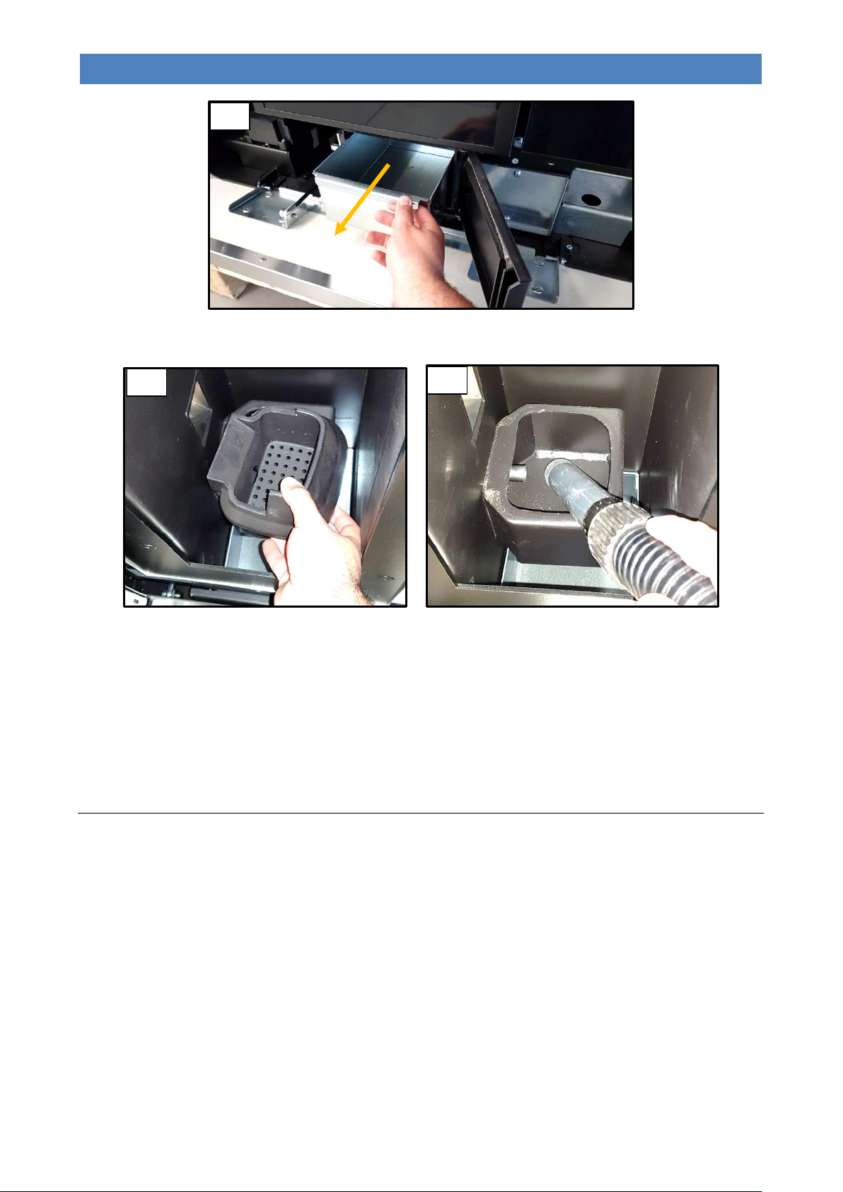
Empty the ash drawer (Figure 1).
Thoroughly clean the brazier from combustion residues by taking it out from its position and removing any residues
inside (Figure 2). Use a suitable ash vacuum device to remove any ash deposited under the brazier (Figure 3).
To remove any deposits, it is also recommended that you scrape the inner walls of the combustion chamber with a
spatula. Do not use tools that can reduce the thickness of the metal sheet of the boiler unit.
WARNING: use suitable ash vacuum devices equipped with a fine mesh filter in order to prevent ash from being
blown into the room and to prevent damaging the vacuum cleaner. We do not recommend the use of normal
vacuum cleaners.
Non-routine cleaning
The extraordinary cleaning of the appliance must be done at least every 90 days so as to always guarantee efficient
performance and optimal operation. Please proceed as follows:
Perform routine cleaning;
30
Page 34
DIVA SLIM PELLET BOILER STOVE
EN - Rev. 1.0
6 5 8
4
7
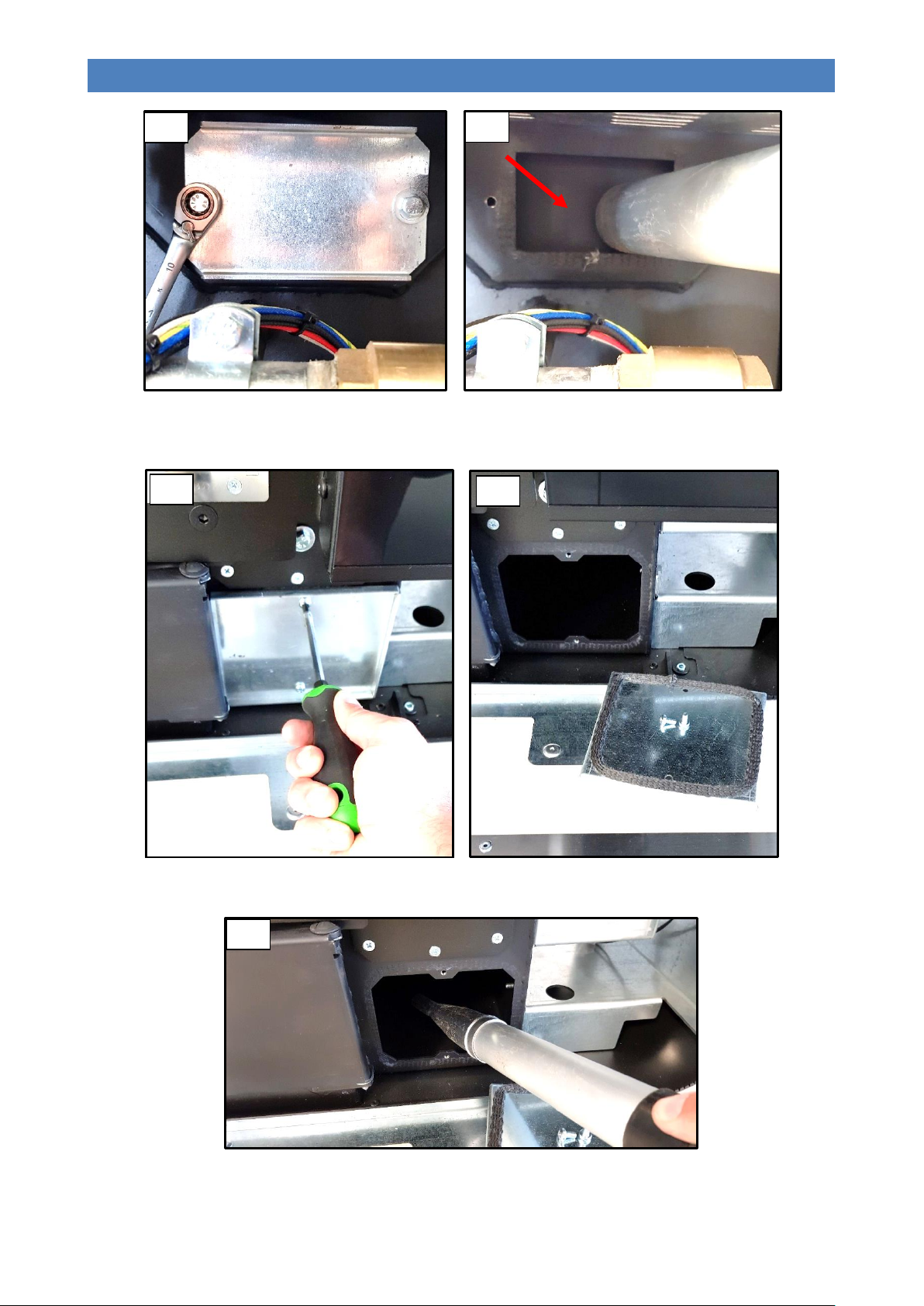
Remove the “flue gas path side (right-hand side) inspection plate” by loosening the 2 screws (Figure 4) and suck up any
ash deposits inside it (Figure 5).
After opening the “lower inspection compartment”, remove the “flue gas path front inspection plate” (Figures 6 and 7).
Remove the deposits inside it using a suitable ash vacuum device (Figure 8). After completing this operation, put the
“flue gas path front inspection plate” back into place and check its airtightness.
31
Page 35
DIVA SLIM PELLET BOILER STOVE
EN - Rev. 1.0
11
12 9 10
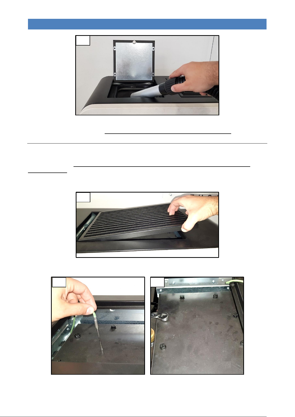
To ensure correct operation, it is necessary to remove the sawdust deposited on the base of the tank (Figure 9) at least
once every 30 days. The pellet tank must be emptied at the end of every season.
Annual cleaning
The annual cleaning of the appliance must be done at least once a year so as to always guarantee efficient performance
and optimal operation. To complete these operations, we recommend contacting the Authorised Technical
Assistance Centre, which will proceed as explained below:
Perform routine and extraordinary cleaning;
Remove the upper grille (Figure 10).
Pull the probe out of the upper cover (Figure 11) and unscrew the eight hex head screws to remove the latter (Figure 12).
32
Page 36
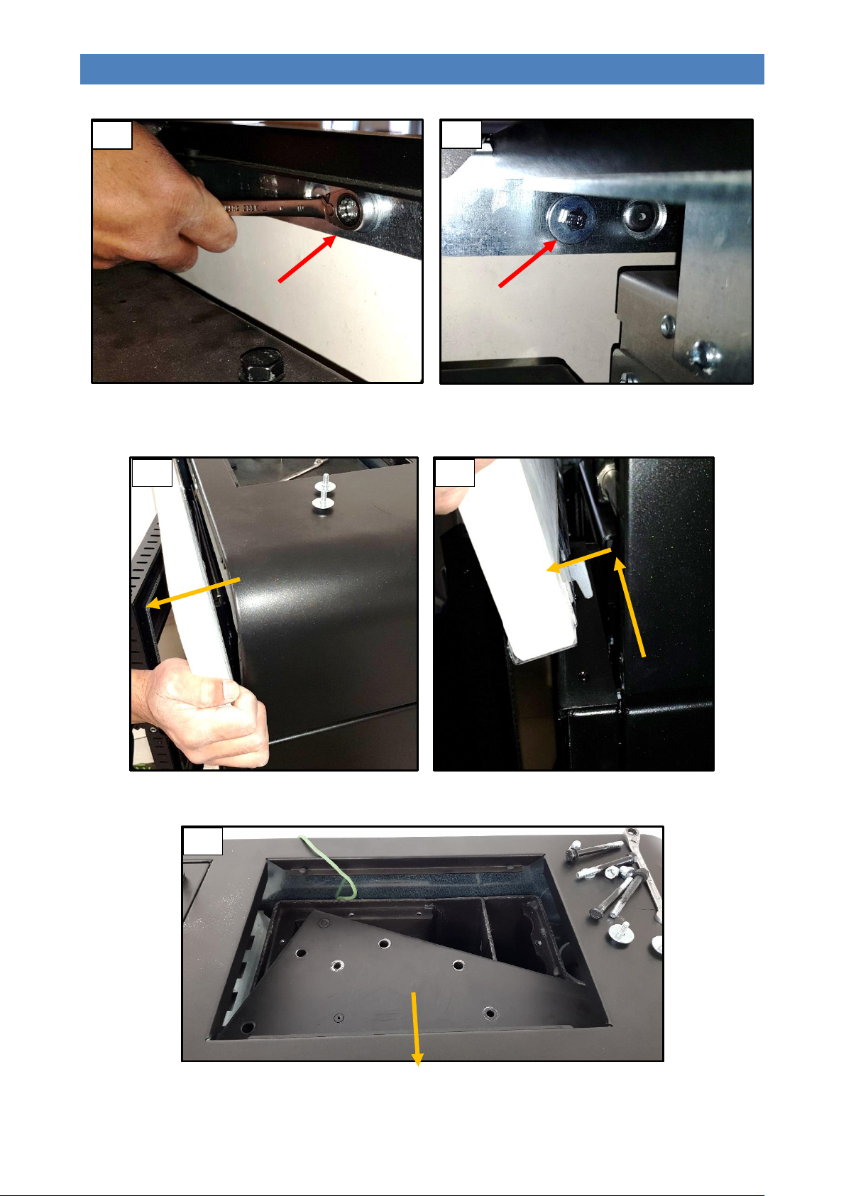
DIVA SLIM PELLET BOILER STOVE
EN - Rev. 1.0
13
14
1
2
17
16
15
Remove the hex head screws that fasten the “Upper front inspection compartment” on the inside
(Figures 13 and 14).
Turn the “Upper front inspection compartment” (Figure 15) forwards and raise it to remove it (Figure 16).
Remove the upper lid by pulling it forward (Figure 17).
33
Page 37
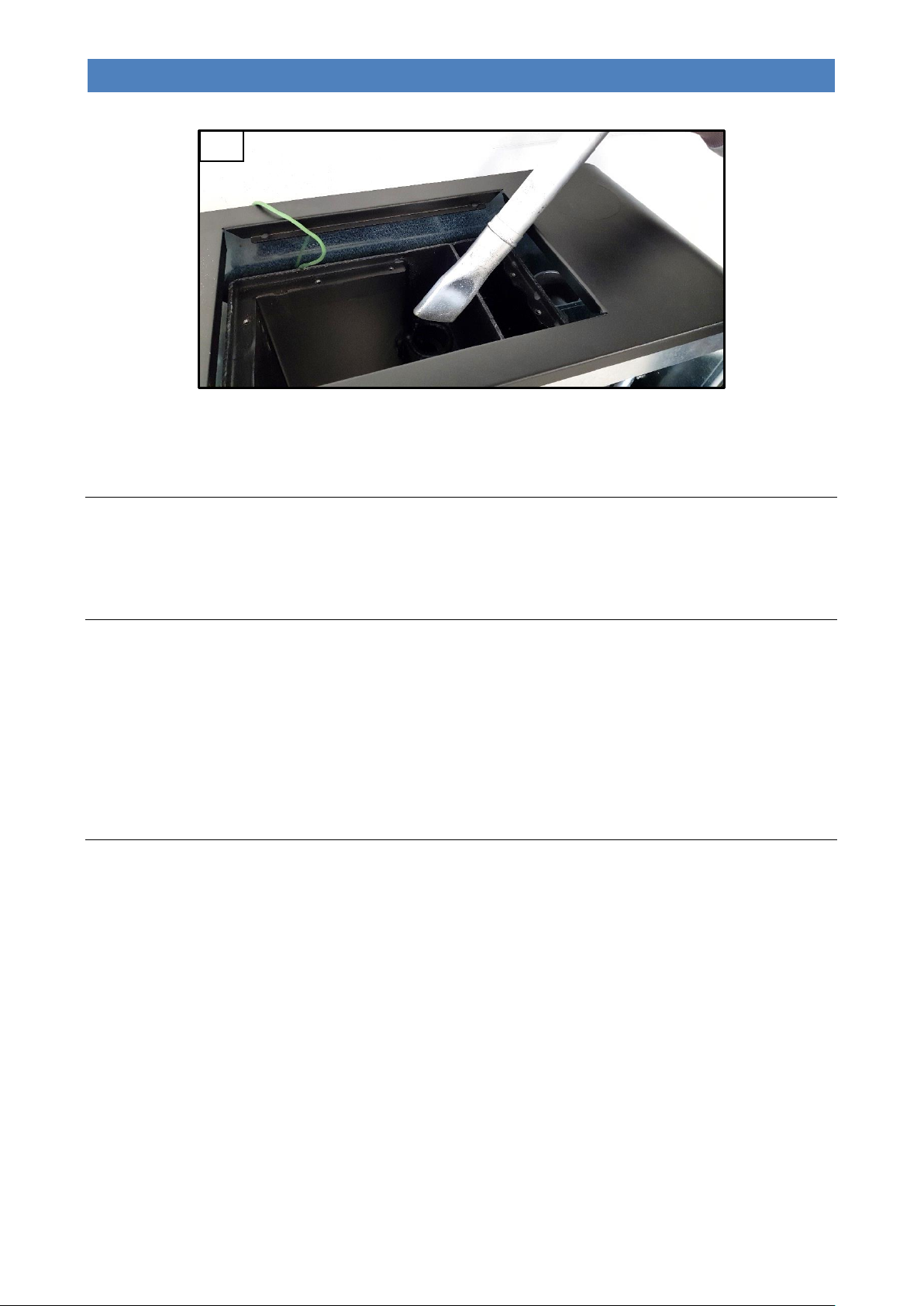
DIVA SLIM PELLET BOILER STOVE
EN - Rev. 1.0
18
Vacuum the ash residues inside combustion chamber of the flue gas path (Figure 18).
After completing this operation, put the previously removed components back in place.
Cleaning the ceramic glass
Always clean the glass when the appliance is off and has cooled down completely. Use a damp cloth or a detergent
specifically formulated for ceramic glass. Do not use abrasive sponges. Do not clean the glass if still warm; changes in
temperature can lead to breakage.
Cleaning the flue
The flue must be cleaned at least once a year, at the beginning of winter, and whenever it becomes necessary.
It is important to check for any obstructions in the flue before switching the appliance on following long periods of
inactivity.
If the flue is not cleaned, the operation of the appliance and its components may be compromised.
The cleaning frequency of the appliance and flue depends on the quality of the pellets used.
USE TOP QUALITY PELLETS TO OBTAIN THE BEST RESULTS.
Maintenance
Timely and systematic maintenance is essential for guaranteeing correct operation, optimal heat performance and
durability of the device. Therefore, qualified staff should check the appliance at least once a year at the beginning of the
season.
You must periodically check the seals because the latter guarantee the air- and water-tightness of the appliance and its
good functioning; if they are worn or damaged you need to be replace them immediately by contacting a Klover
Authorised technical assistance centre.
For proper operation, the appliance must undergo routine maintenance performed by a Klover Authorised
technical assistance centre at least once a year.
34
Page 38

DIVA SLIM PELLET BOILER STOVE
EN - Rev. 1.0
Parameters “VARIOUS SETTINGS” - Mod. DSL (i06_160518)
Parameter
Menu level
Description
Display
Measurement
Value field
Database
L0
Pr38
M08 – 4 – 01
Re-ignition block
RE-IGNIT BLOCK
Minutes
0 – 10
6
Pr39
M08 – 4 – 02
Flue gas extractor switch-off time
MIN-EXT OFF
Minutes
0 – 20
10
Pr40
M08 – 4 – 03
Pre-loading time in ignition
IGNIT PRE-LOAD
Seconds
0 – 255
160
Pr41
M08 – 4 – 04
Stand-by time after pre-loading
AFTER-PRE STANDBY
Seconds
0 – 255
180
Pr42
M08 – 4 – 05
Extractor speed in pre-loading phase
DESP.PR. PRELOAD
RPM
350 – 2800
2200
Pr43
M08 – 4 – 06
ON/OFF temperature hysteresis on “SET H2O”
DELTA ON OFF AUTO
°C
0.0 – 20.0
5.0
Pr44
M08 – 4 – 07
Delay at economy operation mode switch-off (timer after reaching “SET
H2O”)
DELAY-OFF AUTO
Minutes
2 – 120
20
Pr45
M08 – 4 – 08
Power change delay
POWER CHANGE
Seconds
0 – 60
20
Pr46
M08 – 4 – 09
ON/OFF Temperature hysteresis on “SET ROOM”
DELTA ON AUTO
°C
0.0 – 15.0
2.0
Pr47
M08 – 4 – 10
Keypad lock enable
KEY LOCK-EN
On – off
On – off
Off
Pr48
M08 – 4 – 11
Time after which an alarm is triggered in the event of a blackout
BLACKOUT IGNITION
Seconds
0 – 60
30
Pr49
M08 – 4 – 12
Pellet level sensor enable
PELLET RESERVE
On – off
On – off
On
Pr50
M08 – 4 – 13
Pump start threshold and power modulation for overheating safety
PUMP SAFETY
°C
60 – 90
80
Pr51
M08 – 4 – 14
3-way switching and re-ignition delta on “SET BOILER” and “SET
PUFFER”
DELTA PUF-BOI
°C
0 – 15
5
Pr52
M08 – 4 – 15
Preheating time
PRE-HEAT TIME
Seconds
0 – 480
0
Pr53
M08 – 4 – 16
Extractor speed in preheating phase
PRE-HEAT GASSPEED
RPM
500 – 2800
2800
Pr54
M08 – 4 – 17
Time after which the “NO PELLET” alarm is triggered if “PELLET
RESERVE”
RESERVE ALARM
Minutes
1 – 180
40
Pr55
M08 – 4 – 18
ON time for turbulator cleaning gear motor
TURBOLAT DURATION
Seconds
0 – 600”
120
Pr56
M08 – 4 – 19
ON time for brazier cleaning gear motor (NOT USED)
CLEANING TIME
Seconds
0 – 120”
0
Pr57
M08 – 4 – 20
Time from switching off after which the brazier cleaning takes place (NOT
USED)
CLEANER DELAY
Minutes
1 – 15’
1
Pr58
M08 – 4 – 21
Time from switching ON after which the brazier cleaning takes place (NOT
USED)
CLEANER STAND-BY
Hours
1 – 24
24
Pr59
M08 – 4 – 22
Pump activation threshold and switching 3-way valve in DHW OUTPUT
MODE (with Type 2 System)
PUMP THRESHOLD I2
°C
55 – 75
60
Parameters “VACUUM CALIBRATIONS” - Mod. DSL (i06_160518)
Parameter
Menu level
Description
Display
Measurement
Value field
Database
L0
Pr133
M08 – A – 01
Enable automatic pellet loading vacuum
ENABLE VACUUM
On – off
On – Off
Off
Pr134
M08 – A – 02
Vacuum on time
VACUUM ACTIVE
Seconds
1 – 180
20
Pr135
M08 – A – 03
Vacuum rest time
VACUUM PAUSE
Seconds
5 – 60
10
Pr136
M08 – A – 04
Number of operating cycles
VACUUM CYCLES
Number
1 – 20
15
Pr137
M08 – A – 05
Enables a Vacuum operating test to be performed
VACUUM TEST
On – off
On – off
Off
Parameters “DEFAULT SETTINGS” - Mod. DSL (i06_160518)
Parameter
Menu level
Description
Display
Measurement
Value field
Database
L0
Pr01
M08 – 6 – 01
Ignition cycle maximum time
IGNIT MINUTES
Minutes
5 – 25
18
Pr02
M08 – 6 – 02
Start time
START MINUTES
Minutes
2 – 12
7
PCB PARAMETERS
The parameters stored on the PCB are essential for the correct operation.
The following parameters are already stored during the testing of the appliance directly in the factory; these parameters
are the result of special tests using several types of pellets and must not be changed without the authorisation of Klover
srl so as not to impair the operation of the appliance.
The company shall not be held liable for any damage caused by the incorrect entry of parameters.
Parameters table
35
Page 39

DIVA SLIM PELLET BOILER STOVE
EN - Rev. 1.0
Pr03
M08 – 6 – 03
Time interval between the two brazier cleaning operations
BRAZIER CLEANING
Minutes
3 – 240
55
Pr04
M08 – 6 – 04
Screw feed gear motor ON time in ignition phase
IGNIT SCREWS
Seconds
0.1 – 8.0
1.0
Pr05
M08 – 6 – 05
Screw feed gear motor ON time in start phase
START SCREW
Seconds
0.1 – 8.0
1.2
Pr06
M08 – 6 – 06
Screw feed gear motor ON time in power 1 work phase
OUTPUT 1 SCREW
FEED
Seconds
0.1 – 8.0
2.8
Pr07
M08 – 6 – 07
Screw feed gear motor ON time in power 2 work phase
OUTPUT 2 SCREW
FEED
Seconds
0.1 – 8.0
3.8
Pr08
M08 – 6 – 08
Screw feed gear motor ON time in power 3 work phase
OUTPUT 3 SCREW
FEED
Seconds
0.1 – 8.0
5.0
Pr09
M08 – 6 – 09
Screw feed gear motor ON time in power 4 work phase
OUTPUT 4 SCREW
FEED
Seconds
0.1 – 8.0
6.2
Pr10
M08 – 6 – 10
Screw feed gear motor ON time in power 5 work phase
OUTPUT 5 SCREW
FEED
Seconds
0.1 – 8.0
7.2
Pr11
M08 – 6 – 11
Alarm delay
ALARM DELAY
Seconds
0 – 120
90
Pr12
M08 – 6 – 12
Brazier cleaning duration
BRAZIER CLEANING
Seconds
0 – 120
50
Pr13
M08 – 6 – 13
Flue gas minimum temperature for considering the stove on
MINIMUM THRESHOLD
°C
40 – 600
160
Pr14
M08 – 6 – 14
Flue gas maximum temperature
MAXIMUM
THRESHOLD
°C
200 – 880
800
Pr15
M08 – 6 – 15
Flue gas temperature threshold for the air exchanger start-up (NOT USED)
BLOWER THRESHOLD
°C
200 – 720
720
Pr16
M08 – 6 – 16
Flue gas extraction speed in ignition phase
IGNIT FL GASSPEED
RPM
500 – 2800
2000
Pr17
M08 – 6 – 17
Flue gas extraction speed in start phase
START FLUE GAS
SPEED
RPM
500 – 2800
1900
Pr18
M08 – 6 – 18
Flue gas extraction speed in power 1 work phase
P 1 FLUE GAS SPEED
RPM
500 – 2800
1600
Pr19
M08 – 6 – 19
Flue gas extraction speed in power 2 work phase
P 2 FLUE GAS SPEED
RPM
500 – 2800
1750
Pr20
M08 – 6 – 20
Flue gas extraction speed in power 3 work phase
P 3 FLUE GAS SPEED
RPM
500 – 2800
1950
Pr21
M08 – 6 – 21
Flue gas extraction speed in power 4 work phase
P 4 FLUE GAS SPEED
RPM
500 – 2800
2100
Pr22
M08 – 6 – 22
Flue gas extraction speed in power 5 work phase
P 5 FLUE GAS SPEED
RPM
500 – 2800
2250
Pr23
M08 – 6 – 23
Exchanger 1 motor speed in output 1 working mode (NOT USED)
AIR 1 SPEED
Volt
65 – 225
65
Pr24
M08 – 6 – 24
Exchanger 1 motor speed in output 2 working mode (NOT USED)
AIR 2 SPEED
Volt
65 – 225
65
Pr25
M08 – 6 – 25
Exchanger 1 motor speed in output 3 working mode (NOT USED)
AIR 3 SPEED
Volt
65 – 225
65
Pr26
M08 – 6 – 26
Exchanger 1 motor speed in output 4 working mode (NOT USED)
AIR 4 SPEED
Volt
65 – 225
65
Pr27
M08 – 6 – 27
Exchanger 1 motor speed in output 5 working mode (NOT USED)
AIR 5 SPEED
Volt
65 – 225
65
Pr28
M08 – 6 – 28
Threshold beneath which the appliance is considered to be OFF
THRESHOLD OFF
°C
80 – 600
140
Pr29
M08 – 6 – 29
Flue gas extraction speed in brazier cleaning phase
EXHMOTOR
CLEANING
RPM
500 – 2800
2800
Pr30
M08 – 6 – 30
Screw feed gear motor ON time in cleaning phase
SCREW CLEANING
Seconds
0.0 – 8.0
1.8
Pr31
M08 – 6 – 31
Flue gas extractor encoder enable
(NOT USED)
ENCODER
On – off
On – Off
On
Pr32
M08 – 6 – 32
Screw feed brake time
BRAKE TIME
Seconds
0.0 – 0.5
0.2
Pr33
M08 – 6 – 33
Pump activation threshold
PUMP THRESHOLD
°C
20 – 70
55
Pr34
M08 – 6 – 34
Water pressure switch enable
(NOT USED)
WATER MANOSTAT
On – off
On – Off
On
Pr35
M08 – 6 – 35
Water pressure threshold (NOT USED)
PRESSURE
THRESHOLD
Bar
1.5 – 3.0
2.5
Pr36
M08 – 6 – 36
Screw feed motor reducer ON time in DHW output working mode
DHW SCREW FEED
Seconds
0.1 – 8.0
7.2
Pr37
M08 – 6 – 37
Flue gas intake speed in DHW output working mode
DHW FLUE GAS DEV
RPM
500 – 2800
2250
36
Page 40
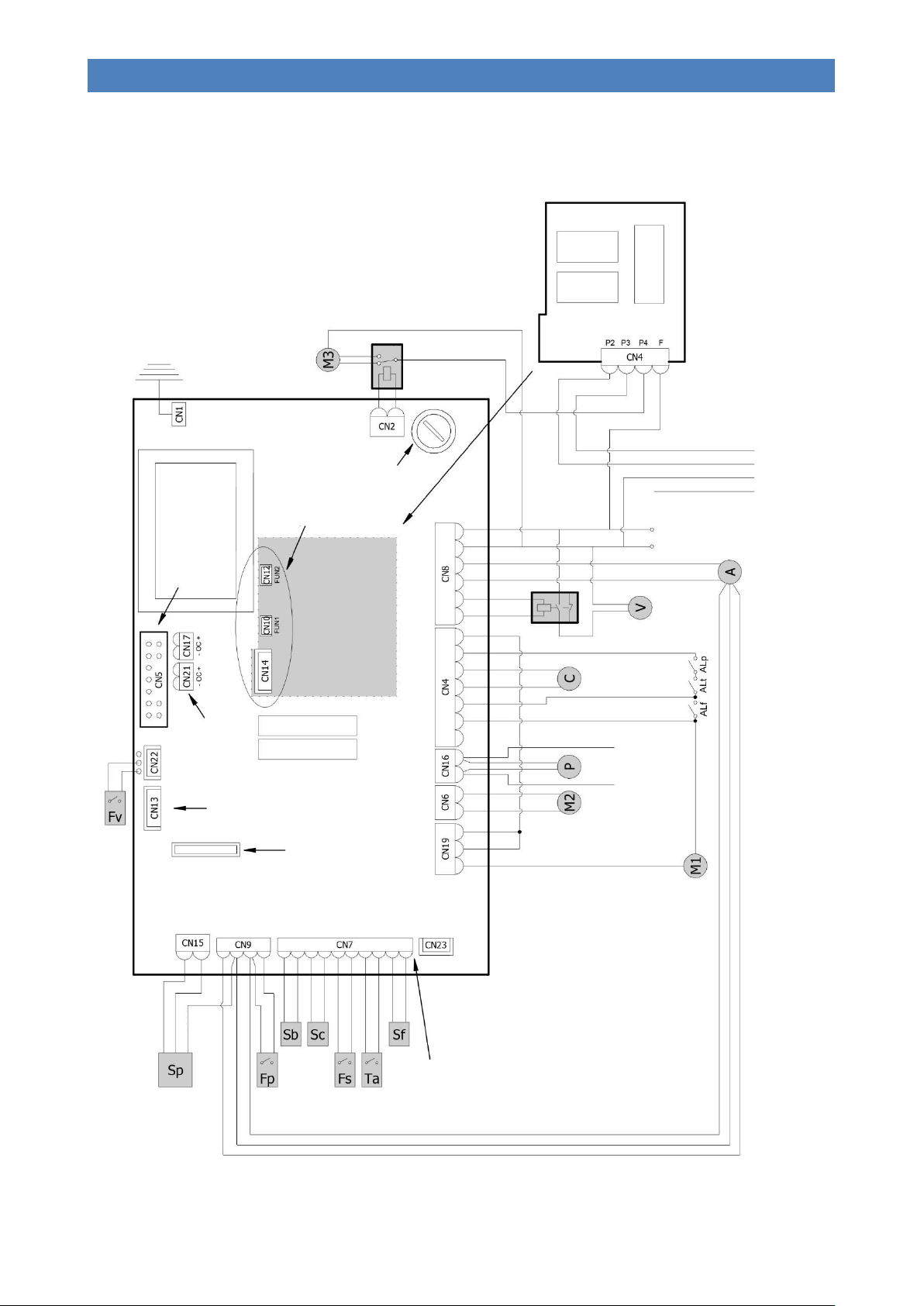
DIVA SLIM PELLET BOILER STOVE
EN - Rev. 1.0
Earth
L023_8 BOARD
AUX1
4 A 5X20
FUSE
TRANSFORMER
IGNITION RELAY
DISPLAY
CONNECTOR
PBC RELAY
CONNECTOR FOR
BOOTLOADER
CONNECTION
PROGRAMMABLE TIMER-
CONTROLLED
THERMOSTAT CLOCK
BATTERY (TYPE CR2032 3
Volt)
Q055 EXPANSION
BOARD
CONNECTED TO
L023_8 WITH
CONNECTORS
CN10, CN12 AND
CN14
FOR THE ELECTRICAL CONNECTION TO THE
COUPLED BOILER, IT IS ADVISABLE TO
CONNECT A RELAY AT THE OUTPUT OF THE
DEDICATED WIRES BECAUSE THESE ARE
POWERED AT 230 V.
Q055 EXPANSION BOARD
(OPTIONAL)
FUSE
3.15 A 5X20
RELAY
RELAY
RELAY
COMPONENT LEGEND:
M1 = Screw feeder gearmotor
M2 = Turbulator cleaning gearmotor
M3 = Brazier cleaning gearmotor (configured
models only)
C = Ignition plug
A = Flue gas extractor with tachometer
P = Pump
V = Auxiliary pellet loading vacuum motor (optional
configuration)
GREEN WHITE
SAFETY DEVICE KEY:
ALp = Fire door closure micro switch
ALf = Flue gas pressure switch
ALt = Manual reset thermostat
LEGEND FOR PROBES / CONTACTS / SENSORS
Sf = “Thermocouple type K” flue gas probe
Sc = Boiler H2O sensor “NTC type 10k ± 1%”
Sb = H2O integrated/external cylinder “NTC
type 10K ± 1%" (optional configuration)
Ta = Room thermostat contact
Fs = DHW flow switch (optional configuration)
Fp = Brazier cleaning micro-limit switch (configured
models only)
Sp = Pellet level sensor (mod. K048
Fv = Auxiliary vacuum loading closure micro switch
(optional preparation)
IMPORTANT: DO NOT
INVERT THE WIRES
REMOTE
CONTROL
CONNECTOR
Live
Neutral
NETWORK
230 VAC
ENC. SC.F.
BLUE
SERIAL
DISPLAY
CONTACTOR
BLACK ON CABLE
BROWN ON CABLE
BLUE ON CABLE
YELLOW/GREEN GROUND
BROWN
CONFIGURATION
FOR CONTROLLING A
COUPLED BOILER, IF
CONNECTED
CONFIGURATION FOR
CONNECTION OF THREE
-
VALVE (DHW control)
SC.F. EXCH. FLUE GAS N F
requested)
Cable for tachometer connection
AUXIN ENC +5V GND BLU PELLETS H2o AMB THERM +TC1- PMP PWM
WIRING DIAGRAM
-DRIVEN
WAY MOTOR
37
Page 41

DIVA SLIM PELLET BOILER STOVE
EN - Rev. 1.0
STANDARD WARRANTY CONDITIONS
1. General information
This standard warranty (“Klover Warranty”) is issued by Klover Srl, San Bonifacio, Via A. Volta no. 8, for the products
shown on the website www.klover.it (the “Products”). The Klover Warranty does not affect the rights provided for by
European directive 99/44/EC or by Italian legislative decree no. 206/2005 “Consumer Code”, where applicable.
The Klover Warranty is limited to Italy. Klover Srl invites Consumers not based in Italy to contact the dealer from which
they bought the Product, to obtain the current warranty conditions.
2. Activation of Warranty
The Klover Warranty must be activated, within 60 days from the date of purchase, on the website www.klover.it in the
section “Register your warranty”. The requested details should be completed, and a delivery note or other fiscal proof of
purchase (e.g. receipt) should be attached.
Alternatively, the warranty certificate, which can be found in each Product pack (the “Warranty Certificate”) must be
sent to Klover Srl, within the same period of 60 days from the date of purchase, by following the instructions on the
certificate.
When registering or sending the guarantee, please ensure that the customer copy of the Warranty Certificate is retained.
It must be duly completed and signed by the Consumer and by the installer, together with the delivery note or other form
of proof of purchase, in order for the Klover Warranty to be valid.
3. Two-year Klover Warranty
The Klover Warranty covers the free repair of the Product all parts of the Product that are found to be defective at origin,
due to defects confirmed by Klover Srl to be exclusively attributable to the manufacturer. If it is not possible to repair the
Product in any way, it will be replaced. In both cases, there will be no change to the expiry or terms of the warranty
provided when the Product was purchased.
The Klover Warranty offers all the advantages of a service guaranteed directly by Klover Srl through its network of
authorised service centres (Centri di Assistenza Tecnica or “C.A.T.”) in Italy. The list can be found on the website
www.klover.it.
The Klover Warranty will remain in effect for a period of 2 years from the date of purchase, if proven by a delivery note or
other proof of purchase (e.g. receipt), stating the name of the seller, the product that was bought, and the date of
purchase.
Product components replaced by an authorised dealer at the Consumer’s expense as they were “out of warranty” after
expiry of the two-year period will be guaranteed by Klover Srl for one year from the date of replacement, excluding costs
of intervention, labour and ancillary costs.
4. Five-year Klover Warranty
If the First Switch-on service is provided by an authorised dealer, within 90 days from the date of purchase, the
Consumer will be entitled to the Warranty on the main boiler unit for a period of 5 years from the date of purchase.
The cost of the First Switch-on service is paid by the Consumer.
This Klover Warranty is valid on condition that the seasonal maintenance is performed by the local service centre as
indicated in the user manual (for example, Safe Top boiler units require annual use of the Long Life protection).
The First Switch-on Report, duly completed and signed, must be kept carefully to ensure that the Klover Warranty
remains operational.
5. Complaints and Assistance
As provided for by Legislative Decree 24/2002, complaints should be sent to the retailer through whom the Product was
bought.
Once the retailer has checked that the Klover Warranty is in force and has not been invalidated, they will contact the
local service centre to agree the terms of intervention to verify and eliminate the reported fault. If the Consumer contacts
the service centre directly, the service centre must immediately inform the retailer from whom the Product was bought.
If, while inspecting the Product, the service centre finds that the reported defect is not one of the defects covered by the
Warranty, the call-out and any works completed, will be paid by the Consumer.
In order to improve the service and reduce intervention time, Consumers are asked to provide the details of the Product
they are calling about. In particular, the following information should be provided: • Warranty Certificate number • the
name, model and serial number of the Product • the date of purchase • the reported defect.
Klover Srl will not be liable for any delays in carrying out repairs or replacements of the Product.
38
Page 42

DIVA SLIM PELLET BOILER STOVE
EN - Rev. 1.0
6. Disclaimer
Klover Products must undergo functional testing before any related masonry works are carried out (for example before
tiling, installation of pilasters, or painting of the walls). Klover Srl is not liable for any costs incurred as a result of removal
and/or reconstruction of related installations, or for any other ancillary intervention even if it is the result of works to
replace defective parts.
Klover Srl is not liable for any faults in the Product that may be attributable to external conditions and/or events, including
but not limited to insufficient installation capacity, mis-installation, lack of maintenance for maintenance not carried out in
accordance with the instructions in the user manual, or misuse of the Product. The cost of any works will be paid by the
Consumer in such cases.
Klover Srl declines all liability in respect of any loss or damage that may be caused directly or indirectly to the Consumer
and/or to a third party or to persons, animals or property as a result of failure to comply with all the relevant instructions
concerning installation, use and maintenance of the Product. The injured party must prove the loss or damage, the
defect, and the causal connection, and must the retailer from which the Product was bought, in accordance with
Legislative Decree 24/2002.
7. Exclusions from Klover Warranty
The Klover Warranty does not include:
• Defects in the Product that are not attributable to manufacturing defects • Defects in the products related to mis-
installation or inappropriate installation • Defects related to improper functioning of the chimney flue • Defects in the
Product caused by negligence, accidental breakage, normal wear and tear, tampering and/or damage during transport
(scratches, dents etc.), including shipments sent free to destination, works carried out by unauthorised personnel, and
additional damage caused by inappropriate intervention by the Consumer • Calibration of settings • Damage caused by
the use of expired or inappropriate fuel • Transport costs.
The Klover Warranty excludes the following Product components:
• Ceramic or tempered glass, ceramic/majolica tiling and/or lacquered steel and/or cast iron. Changes in colour shades,
speckling, superficial cracking, shading and minor dimensional variations are not considered Product defects, but are
characteristics of the artisanal manufacturing process • Painted, chromed or gilded details, handles, dials • All the
external components of the Product on which the Consumer may intervene directly during use and/or maintenance, or
which may be subject to wear and tear and/or the formation of rust, or blemishes on the steel caused by harsh
detergents, in particular the use of wood at a rate that exceeds the recommended hourly capacity, or the use of fuels
that were not recommended or were not included in the instructions • Refractory materials or vermiculite • The pellet
brazier, grille and cast iron cooking plate, the smoke deflector or flame guard, the seals, fuses or batteries in the
Product’s electronic components and any other removable component that may be subject to normal wear and tear •
Electrical and electronic parts found to be faulty as a result of non-standard electrical connections, natural disasters or
voltage variations other than the nominal variation.
8. Forum
The Court of Verona will have sole jurisdiction in the event of a dispute.
39
Page 43

DIVA SLIM PELLET BOILER STOVE
EN - Rev. 1.0
40
Page 44

Cod. CS.IST.DSL-EN
KLOVER Srl
Via A. Volta, 8
37047 San Bonifacio (VR)
VAT No. 02324280235
www.klover.it
 Loading...