

klover STAR 14, DIVA PLUS, MAGNIFIKA, PELLET FIRE PLACE 18, BI-FIRE MID Technical Manual
...Page 1

IDRO FIRMWARE
with LED display
S
E
T
OK
Set
°C
1
2
3 4
6
5
TECHNICAL MANUAL
Updated on 02/07/13 – Rev. 2.5
Installed on:
STAR 14 – STAR 14 Sartoriale
DIVA
DIVA MID
DIVA PLUS
MAGNIFIKA
PELLET FIRE PLACE 18
BI-FIRE MID
BI-FIRE
Page 2

2
Page 3

3
TABLE OF CONTENTS
1. GENERAL DESCRIPTION ............................................................................................................................................ 4
1.1 Console ..................................................................................................................................................................... 4
1.2 What are the buttons for ............................................................................................................................................ 6
2. THE MENU - CHRONO-THERMOSTAT ....................................................................................................................... 7
3. OPERATIVE MODE ...................................................................................................................................................... 8
3.1 Stove ignition............................................................................................................................................................. 8
3.2 No stove ignition........................................................................................................................................................ 9
3.3 Stove working............................................................................................................................................................ 9
3.4 Modification of DHW and water temperature setting ................................................................................................. 9
4. TEMPERATURE PROBES ......................................................................................................................................... 10
4.1 Room/water temperature probe .............................................................................................................................. 10
4.2 Pellet flue gas temperature probe ........................................................................................................................... 11
4.3 Wood flue gas temperature probe (BI-FIRE MID – BI-FIRE wood side) ................................................................. 11
5. WHAT HAPPENS IF... ................................................................................................................................................. 12
6. ALARMS ...................................................................................................................................................................... 12
7. FUNCTIONING PRINCIPLE ........................................................................................................................................ 13
7.1 Ignition cycle ........................................................................................................................................................... 13
7.2 Work phase ............................................................................................................................................................. 15
7.3 DHW power work phase ......................................................................................................................................... 17
7.4 Work phase with open room thermostat contact ..................................................................................................... 19
7.5 BI-FIRE MID and BI-FIRE Functioning principle ..................................................................................................... 21
8. BOOTLOADER PROGRAMMER ................................................................................................................................ 22
8.1 Firmware loading in power board ............................................................................................................................ 22
9. DATABASE ................................................................................................................................................................. 23
9.1 DATABASE access keys ........................................................................................................................................ 23
10. POWER BOARD CALIBRATIONS .......................................................................................................................... 24
10.1 Calibrations access keys reserved to T.A.C. table .................................................................................................. 24
10.2 How to calibrate parameters ................................................................................................................................... 24
10.3 How to calibrate pellet flue gas probe ..................................................................................................................... 25
11. PARAMETERS TABLES ......................................................................................................................................... 26
12. PARAMETERS EXPLANATION ............................................................................................................................. 34
13. WIRING DIAGRAMS ............................................................................................................................................... 39
13.1 DIVA – STAR14 wiring diagram (Motherboard I023) ............................................................................................ 39
13.2 DIVA MID – DIVA PLUS wiring diagram (Motherboard I023) ................................................................................. 40
13.3 MAGNIFIKA wiring diagram (Motherboard I023).................................................................................................... 41
13.4 PELLET FIRE PLACE 18 wiring diagram (Motherboard I023) .............................................................................. 42
13.5 BI-FIRE MID – BI-FIRE wiring diagram (Motherboard I023) ................................................................................. 43
14. USEFUL ADVICE .................................................................................................................................................... 44
15. NOTES .................................................................................................................................................................... 45
Page 4

4
1. GENERAL DESCRIPTION
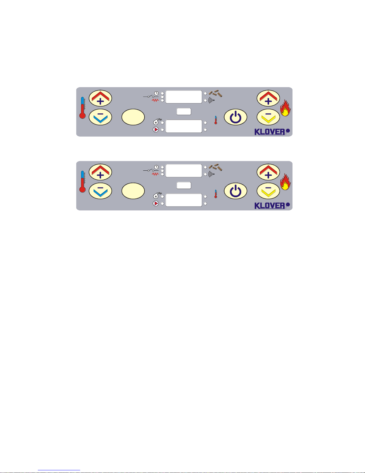
1.1 Console
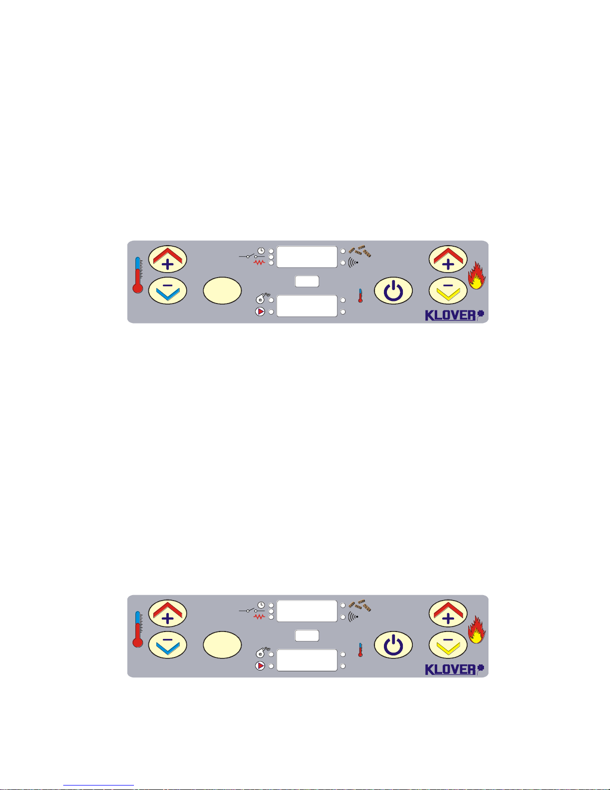
The equipment's functioning state is displayed by the console. Many types of displays and the
available settings based on the selected menu can be made by accessing the menu.
Figure 1 shows the display in equipment on conditions.
SET
OK
Set
°C
1
2 3 4 6
5
60°C
Po 5
Figure 2 shows the display in equipment on conditions (on products with ventilation).
SET
OK
Set
°C
1
2 3 4 6
5
60°C 2
P5 2
Figure 3 shows the display in equipment on conditions (on pellet/wood combined products).
SET
OK
Set
°C
1
2 3 4 6
5
60°C
P5 L
EFFECTIVE WORK POWER (modulation)
Fig. 2
BOILER WATER TEMPERATURE
WORK POWER
VENTILATION POWER (optional)
Fig. 3
BOILER WATER TEMPERATURE
WORK POWER
WOOD SIDE ON
Fig. 1
BOILER WATER TEMPERATURE
WORK POWER
Page 5
5
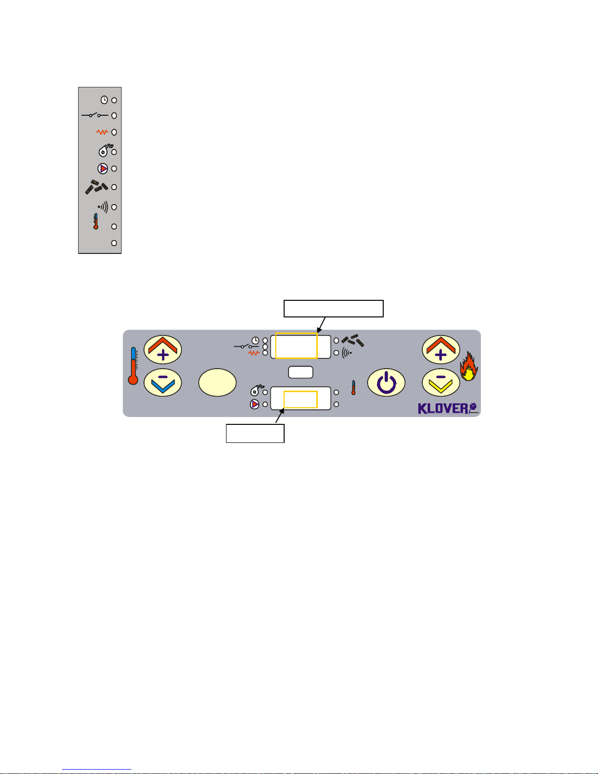
Figure 4 describes the meaning of the state LEDs on the display's console (1st LED SERIES).
°C
OK
SET
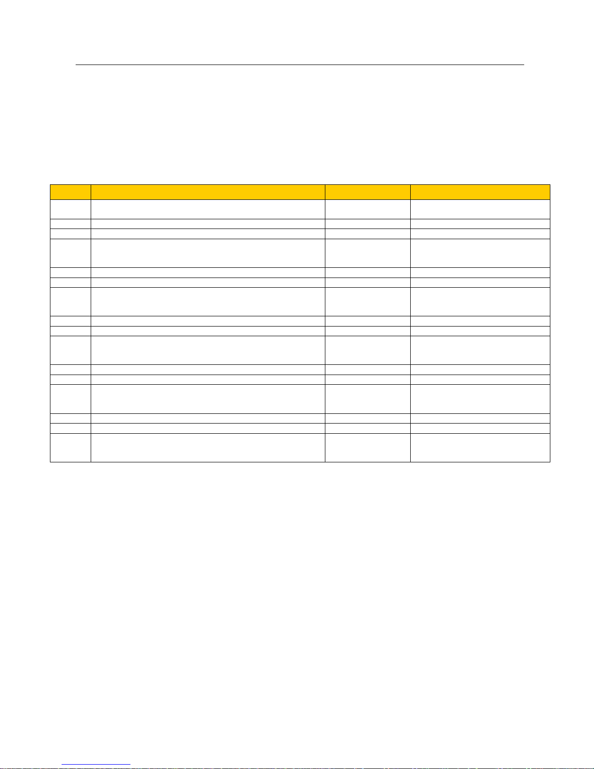
Figure 5 shows the display during operative parameters setting or programming.
SET
OK
Set
°C
1
2 3 4 6
5
Lun
Ut 01
The MENU LEVEL area shows the current parameter/menu level.
The INPUT area shows the entered programming values.
CHRONO-THERMOSTAT: the LED is on when at least one ignition and switch-off program is
active.
ROOM THERMOSTAT: the LED is on when room thermostat contact is open.
IGNITION RESISTANCE: the LED is on when ignition resistance is active.
FLUE GAS EXTRACTOR: the LED is on when the flue gas intake device is active.
PUMP: the LED is on when system circulation pump is active.
SCREW FEED: the LED is on when the pellet load motor reducer switches on.
REMOTE CONTROL RECEPTION: the LED is on when a button on the supplied remote control is
pressed and signal reaches the board.
TEMPERATURE OK: the LED is on when temperature set on SET H2O is reached.
SET: the LED is on when SET button on display is pressed.
Fig. 4
Fig. 5
INPUT
MENU LEVEL
Page 6

6
1.2 What are the buttons for
BUTTON
DESCRIPTION
MODE
ACTION
1
Increases temperature (1)
In programming..
Modifies/increases the selected menu value.
Working/off (after having
pressed SET once).
Increases DHW/water thermostat
temperature value.
2
Decreases temperature (2)
In programming..
Modifies/decreases the selected menu
value.
Working/off (after having
pressed SET once).
Decreases DHW/water thermostat
temperature value.
3
Set
-
Pressed once accesses “SET H2O” or “SET
SANI”.
Consecutively pressed twice accesses the
user menu.
In menu..
Accesses the subsequent sub-menu level.
In parameters programming..
Sets parameter value and goes to
subsequent parameter.
4
ON/OFF
Outlet
Working..
Ignites and switches off stove when pressed
for 2 seconds.
In alarm block..
Releases alarm.
In menu/programming..
Goes to upper menu level memorising the
made modifications.
5
Increases power (3)
Working/off..
Increases stove's work power.
In menu..
Goes to previous menu entry.
In programming..
Goes back to previous sub-menu entry
memorising the made modifications.
6 Decreases power (4)
Working/off..
Decreases stove's work power.
In menu..
Goes to subsequent menu entry.
In programming..
Goes back to subsequent sub-menu entry
memorising the made modifications.
(1) The flue gas temperature is displayed on upper display and water in boiler temperature on lower
display when held down.
(2) Current time is displayed when held down.
(3) Keep pressed for two seconds go directly to work phase, skipping the entire ignition cycle (see “Useful
advice”).
(4) Keep pressed for a few seconds (during switch-off) to switch-off flue gas intake device and proceed
with new stove ignition without having to wait "Stand-by" time (see “Useful advice”).
Page 7
7
2. THE MENU - CHRONO-THERMOSTAT
The Menu is accessed by pressing key 3 (Set) twice.
This is divided into different levels (called UT...) to access the board's programming and settings.
The technical programming access menu entry (UT04) (parameters reserved to Technical Assistance Centre)
is protected by access key (see “Power board calibrations”).
The menu structure is summarised in the following table:
MENU
MEANING
VALUE
VALUE THAT CAN BE SET
UT01
Set current day or OFF (the chrono-thermostat is completely
deactivated by setting OFF).
Day or OFF
OFF, Mon, Tues, Wed,…..Sun
UT02
Set current time.
Hour
From 00 to 23
UT03
Set current minutes.
minutes
From 00 to 59
UT04
The various parameters tables reserved to Technical
Assistance Centre are accessed by setting one of the access
keys.
-
From 00 to P5
UT05
First program ignition time.
Time
From 00.00 to 23.50 with 10’ steps
UT06
First program switch-off time.
Time
From 00.00 to 23.50 with 10’ steps
UT07
Choice of days first program is to be considered
(program times will be considered by setting ON on day;
program times will not be considered by setting OFF on day).
Day/State
Mon on/off, Tues on/off, Wed
on/off, Thurs on/off, Fri on/off, Sat
on/off, Sun on/off
UT08
Second program ignition time.
Time
From 00.00 to 23.50 with 10’ steps
UT09
Second program switch-off time.
Time
From 00.00 to 23.50 with 10’ steps
UT10
Choice of days second program is to be considered (program
times will be considered by setting ON on day; program times
will not be considered by setting OFF on day).
Day/State
Mon on/off, Tues on/off, Wed
on/off, Thurs on/off, Fri on/off, Sat
on/off, Sun on/off
UT11
Third program ignition time.
Time
From 00.00 to 23.50 with 10’ steps
UT12
Third program switch-off time.
Time
From 00.00 to 23.50 with 10’ steps
UT13
Choice of days third program is to be considered
(program times will be considered by setting ON on day;
program times will not be considered by setting OFF on day).
Day/State
Mon on/off, Tues on/off, Wed
on/off, Thurs on/off, Fri on/off, Sat
on/off, Sun on/off
UT14
Fourth program ignition time.
Time
From 00.00 to 23.50 with 10’ steps
UT15
Fourth program switch-off time.
Time
From 00.00 to 23.50 with 10’ steps
UT16
Choice of days fourth program is to be considered
(program times will be considered by setting ON on day;
program times will not be considered by setting OFF on day).
Day/State
Mon on/off, Tues on/off, Wed
on/off, Thurs on/off, Fri on/off, Sat
on/off, Sun on/off
Set “OFF” in user menu Ut01 to deactivate chrono-thermostat.
Page 8
8
3. OPERATIVE MODE
The stove's normal functioning principle with reference to the available functions for the user is
described below.
The display appears as in figure 6 before igniting the stove.
SET
OK
Set
°C
1
2 3 4 6
5
22:35
Off
3.1 Stove ignition
Press key 4 for a few seconds to ignite the stove. Ignition is shown on display as in figure 7.
SET
OK
Set
°C
1
2 3 4 6
5
Asp
Fun
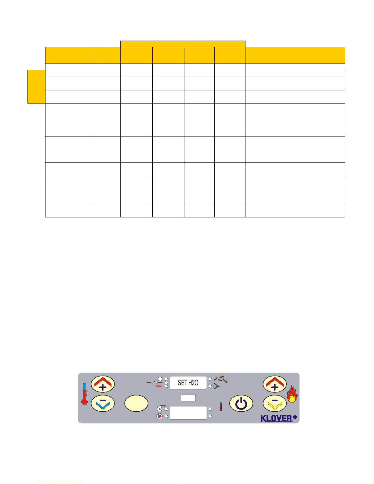
The stove sequentially runs the start-up phases as defined by the parameters managing levels and
timing (see “Parameters tables”), after stove ignition.
The method according to which the stove reaches work condition is shown in the following
prospectus, if alarm or anomaly conditions do not arise.
The various functioning conditions, which cleaning, economy modulation, etc. are also described.
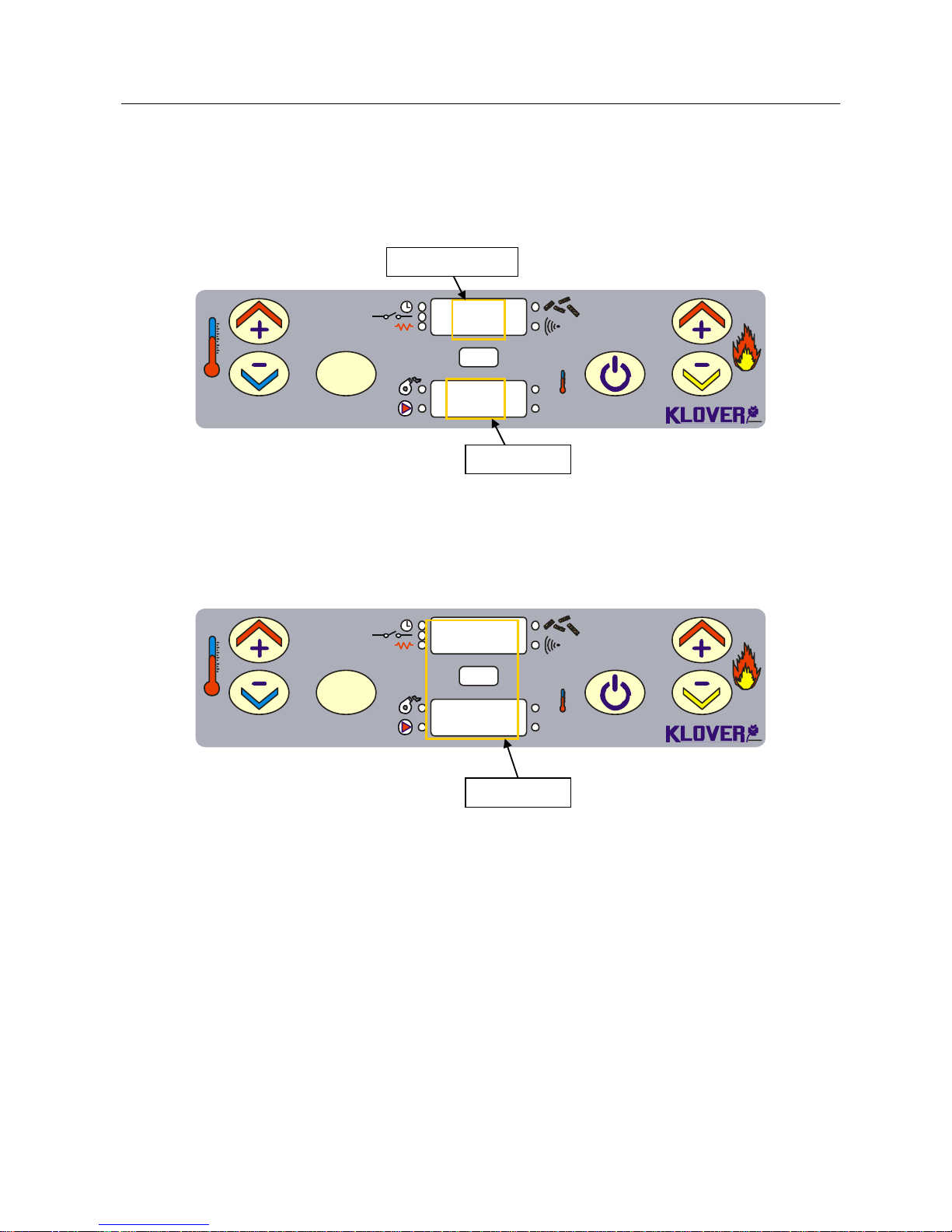
Fig. 6
CLOCK
STOVE STATE
Fig. 7
DIALOGUE
Page 9
9
Devices
Country
Duration
Ignition
resistance
Flue gas
intake
device
Screw feed
Pump
When it occurs
OFF - OFF
OFF
OFF
OFF
ON/OFF
IGNITION
CYCLE
FUN ASP
8”
ON
ON
OFF
OFF
For the first 8" in ignition
LOAD PELL
Pr01
ON
ON
ON
OFF
For a time set on Pr01 or before reaching
temperature on Pr13 after “FUN ASP” state
FIRE ON
Pr02
OFF
ON
ON
OFF/ON
For a time set on Pr02 after “LOAD PELL”
state
“Work from Power 1
to Power 5”
-
OFF
ON
ON
ON
- H2O Temperature < “SET H2O”
- Closed room thermostat contact
- Flue gas temperature < Pr14
- No alarm detected
ECO T-OFF
-
OFF
ON
ON
OFF
- Open room thermostat contact with H2O
temperature < “SET H20” and “SET SANI”
ECO H2O
Pr12 or
Pr23
OFF
ON
ON
OFF/ON *
- Reached temperature set on “SET H2O”
- Reached temperature set on “SET SANI”
STOP FIRE
OFF
OFF
OFF
OFF/ON *
- Exceeded temperature set on Pr12 after
having reached temperature set on “SET
H2O”.
- Exceeded time set on Pr23 after having
reached temperature set on “SET H2O”
COOL FIRE
Pr24
OFF
ON
ON
OFF/ON *
- Lapsed time set on Pr03
* Pump switch-on depends on whether the room thermostat contact is open or closed in this condition. In both cases, the
pump switches on if water in boiler temperature exceeds temperature set on “SET H2O” by 5°C (safety to avoid overtemperature).
3.2 No stove ignition
If the flue gas temperature has not reached Pr13 minimum value admitted after Pr01 time has lapsed,
the stove places itself in “NO FIRE” alarm state.
3.3 Stove working
The stove goes to work phase, representing the normal functioning mode, after positive ignition (for
display conditions see “Console”).
The system pump switches on if water in boiler temperature is higher than Pr15.
3.4 Modification of DHW and water temperature setting
- Water Temperature
Press key 3 to select “SET H2O” (with work power set from Power 1 to Power 5) to modify water
temperature. Press keys 1 and 2. The display appears as in figure 8 during this operation.
S.R.L.
SET
OK
Set
°C
1
2 3 4 6
5
60°C
Wait 5 seconds after setting wanted value.
Fig. 8
Page 10

10
The stove enters functioning economy upon reaching said temperature.
The stove now automatically switches off if at least one of the following conditions exist:
If it remains in Functioning Economy “ECO-H2O” for a time set on Pr23 (120 minute default setting).
If it exceeds temperature differential set on Pr12 (10°C default setting) or H2O Temperature > (“SET
H2O” + Pr12)
- DHW Temperature (only on prepared models)
Press key 3 to select “SET SANI” (with work power set on DHW Power) to modify DHW temperature.
Press keys 1 and 2. The display appears as in figure 9 during this operation.
S.R.L.
SET
OK
Set
°C
1
2 3 4 6
5
65°C
Wait 5 seconds after setting wanted value.
4. TEMPERATURE PROBES
The used temperature probes' features are given below.
4.1 Room/water temperature probe
The room/water probe used to measure water or room (in case of air stoves) temperature has the
following features:
IP67, NTC Thermoplastic probe: like NTC 10K ± 1% = 3435
Measuring field: -50/+120°C
Obtain a tester to check if probe is faulty, set it in ohm and measure the two probe pins (wire ends):
The probe measures about 10kohm at 25°C if it works correctly
If the probe is faulty: - resistance greater than 1Mohm (open)
- resistance to 0 ohm (in short)
The tester can also be used to check if the probe connection to the power board contacts are in short;
if 0 ohm resistance is measured by connecting the tester to the contacts, these are in short.
The lower display shows water (or room) temperature at 02°C if the room/water probe is not
connected to the power board. The display appears as in figure 10.
S.R.L.
SET
OK
Set
°C
1
2 3 4 6
5
Fig. 9
Fig. 10
02°
C
Page 11
11
4.2 Pellet flue gas temperature probe
The flue gas probe used to measure the pellet's flue gas temperature has the following features:
Thermocouple probe: J type
Measuring field: 0/+350°C
Obtain a tester to check if probe is faulty, set it in ohm and measure the two probe pins (wire ends);
however, this only verifies if the probe is interrupted (no change compared to value shown on
unconnected tester).
The tester can also be used to check if the probe connection to the power board contacts are in short;
if 0 ohm resistance is measured by connecting the tester to the contacts, these are in short.
The upper display shows the pellet flue gas temperature (by pressing key 1) at 284°C if the pellet flue
gas probe is not connected to the power board. The display appears as in figure 11.
S.R.L.
SET
OK
Set
°C
1
2 3 4 6
5
Pay attention to wires polarity when connecting the pellet flue gas probe to the power board. A
fixed temperature of 30°C appears on upper display that does not change with the increase of
flue gas temperature if the wires' polarity is inverted.
4.3 Wood flue gas temperature probe (BI-FIRE MID – BI-FIRE wood side)
The flue gas probe used to measure the wood's flue gas temperature has the following features:
2 Wires PT1000 probe: PT 1000 class B
Measuring field: 0/+500°C
Obtain a tester to check if probe is faulty, set it in ohm and measure the two probe pins (wire ends):
The probe measures about 1k 1.1kohm at 25/30°C if it works correctly
If the probe is faulty: - resistance greater than 1Mohm (open)
- resistance to 0 ohm (in short)
The tester can also be used to check if the probe connection to the power board contacts are in short;
if 0 ohm resistance is measured by connecting the tester to the contacts, these are in short.
The lower display shows the wood flue gas temperature (by pressing key 2) at h86°C if the wood flue
gas probe is not connected to the power board. The display appears as in figure 12.
S.R.L.
SET
OK
Set
°C
1
2 3 4 6
5
Fig. 11
284
Fig. 12
LEGn
h86
C
Page 12

12
5. WHAT HAPPENS IF...
...the stove does not ignite
In case of no ignition, the “NO FIRE” alarm is displayed.
Hold button 4 (switch on/off) for a few seconds to restore the stove to standard conditions (remove the alarm).
...lack of power for a few seconds
Once the power is restored, the stove immediately restarts from the status it had before the power outage
(recovering the set work power).
... lack of power
As soon as the power is restored after a power outage, the stove sets on “STOP FIRE” mode and carries out
the entire switch off cycle until its cooling. Once this phase is completed, the stove can be normally switched
on to proceed working at the set power.
…the fire door is open or closed improperly
In case the door is open or closed improperly, the motor reducer cannot be powered electrically, not allowing
the stove to switch on. If the fire door is opened during the normal operation, the stove burns all the pellet in
the brazier, activating the “ALAR NO FIRE” alarm (sudden switch off). The flue is dirty, blocked or not
manufactured correctly.
In case the flue is dirty, blocked or not manufactured correctly, the motor reducer cannot be powered
electrically not allowing the stove to switch on. If the flue blocks during the normal operation, the stove burns
all the pellet in the brazier, activating the “ALAR NO FIRE” alarm (sudden switch off).
...the stove is overheated
In case of water over-temperature in the boiler, the message
“ALAR HOT H2O” is displayed first, followed by an acoustic alarm. At this point the motor reducer is not
electrically powered, because the rearm safety thermostat is activated. Therefore the thermostat must be
rearmed before switching on the stove.
...pellet insert unhooked or hooked improperly
In case the pellet insert is unhooked or hooked improperly, the motor reducer cannot be powered electrically,
not allowing the insert to switch on. If it is unhooked during the normal operation, the insert burns all the pellet
in the brazier, activating the “ALAR NO FIRE” alarm (sudden switch off).
6. ALARMS
The board intervenes and signals the occurred irregularity in case of functioning anomaly, operating in
different mode depending on type of alarm. The following alarms are foreseen in the board.
DISPLAY
ORIGIN OF ALARM
ALAR SOND H2O
Faulty or disconnected water temperature probe
ALAR HOT H2O
Water over-temperature. When water temperature exceeds 92°C
ALAR SOND FUMI
Faulty or disconnected flue gas temperature probe.
ALAR HOT TEMP
Flue gas over-temperature. When flue gas temperature exceeds 280°C
ALAR NO FIRE
No ignition. When flue gas minimum temperature (Pr13) is not reached within
maximum ignition cycle time (Pr01).
ALAR NO FIRE
Sudden switch-off during work phase. When, during work, the flue gas
temperature drops below minimum threshold (Pr13).
NO H2O
No water level. When water in boiler does not reach minimum level (only on
Sicuro Top BI-FIRE and BI-FIRE MID system)
Every alarm causes the equipment to immediately switch-off.
After time set on Pr11 (alarms delay) alarm state is reached; press key 4 to reset it.
Page 13

13
7. FUNCTIONING PRINCIPLE
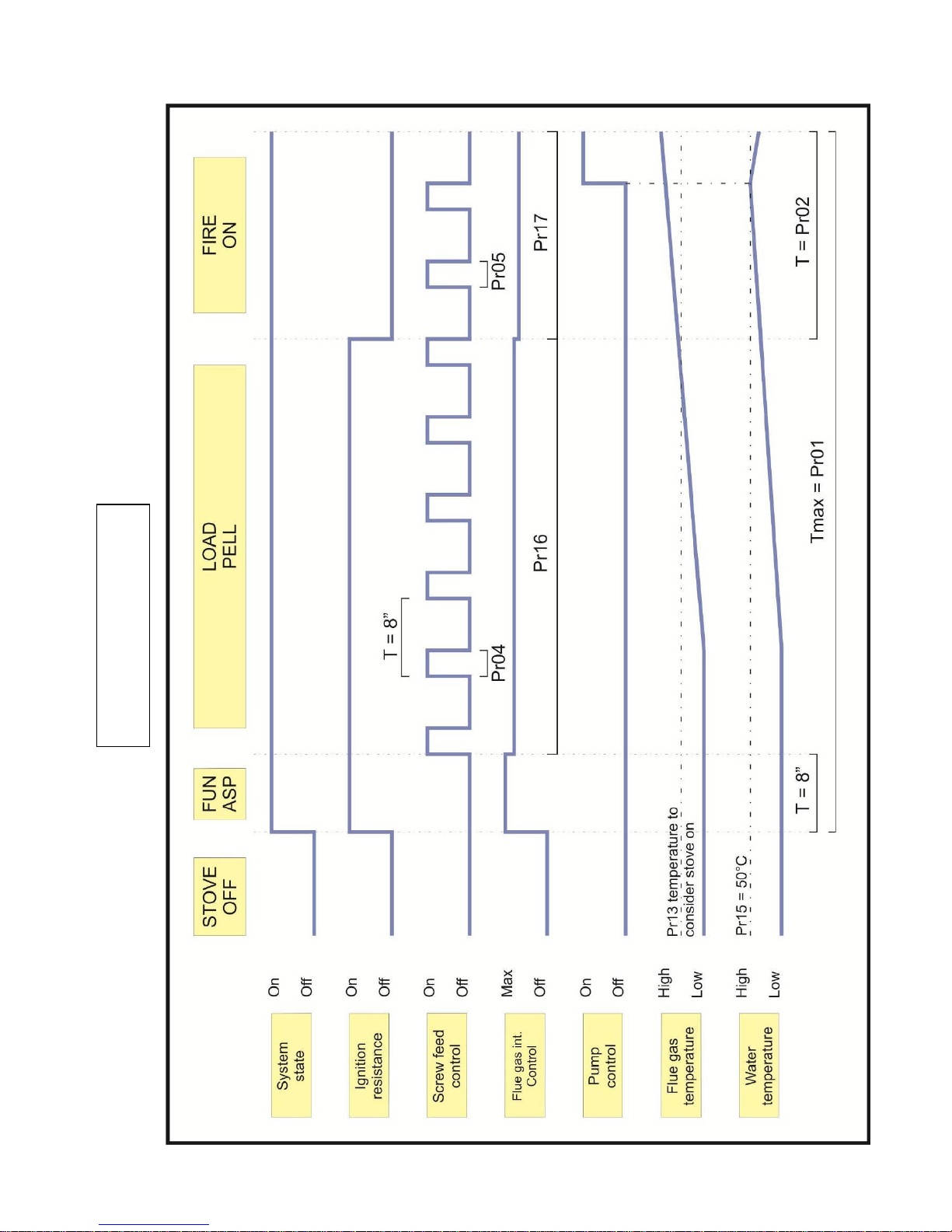
7.1 Ignition cycle
The ignition cycle can last max 18 minutes and is divided into three phases:
1 - FUN ASP : Intake device function
duration 8 seconds
2 - LOAD PELL : Pellet loading and resistance ignition
Pr01 = “LOAD PELL” duration
A pre-load phase may be present in “LOAD PELL” phase with specifications according to parameters Pr45,
Pr46 and Pr47.
3 - FIRE ON : Resistance switch-off and flame stabilising
Pr02 = “FIRE ON” duration
The stove goes to work phase at power set in ignition using buttons 1 and 2 after ignition cycle.
Page 14
14
IGNITION PHASE
Page 15

15
7.2 Work phase
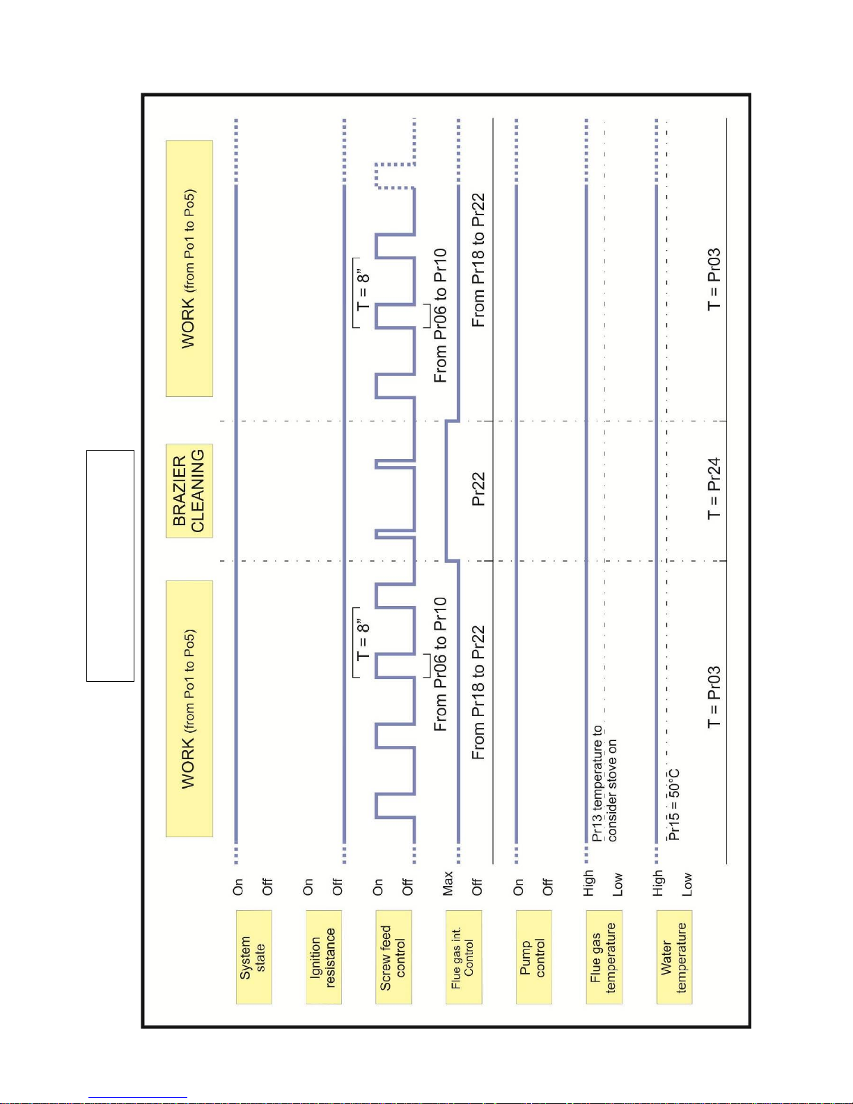
The set work power or 1, 2, 3, 4, 5, SANI (optional) is shown on upper display during the stove's normal
functioning.
A “SET H20” (maximum temperature) can be set by working from Power 1 to Power 5. The stove enters
Functioning Economy “ECO-H2O” upon reaching of such set.
Before reaching temperature set on “SET H20”, the stove starts modulating power by decreasing pellet intake
and reducing flue gas intake device speed.
Example: “SET H2O” set at 75 °C
Work power set at 5
- The work power automatically changes to 4 upon reaching 71°C.
- The work power automatically changes to 3 upon reaching 72°C.
- The work power automatically changes to 2 upon reaching 73°C.
- The work power automatically changes to 1 upon reaching 74°C.
- The work power automatically changes to Functioning economy “ECO H2O” upon reaching 75°C.
The stove now automatically switches off if at least one of the following conditions exist:
If it remains in Functioning Economy “ECO-H2O” for a time set on Pr23 (120 minute default setting).
If it exceeds temperature differential set on Pr12 (10°C default setting) or H2O Temperature > (“SET
H2O” + Pr12)
With the following condition the stove automatically ignites:
If it drops below temperature differential set on Pr12 (10°C default setting) or H2O temperature < (“SET
H2O” – Pr12)
If the above-mentioned condition occurs when the stove is still carrying out the switch off cycle, it is required to
wait until it ends.
Page 16
16
WORK PHASE
Page 17

17
7.3 DHW power work phase
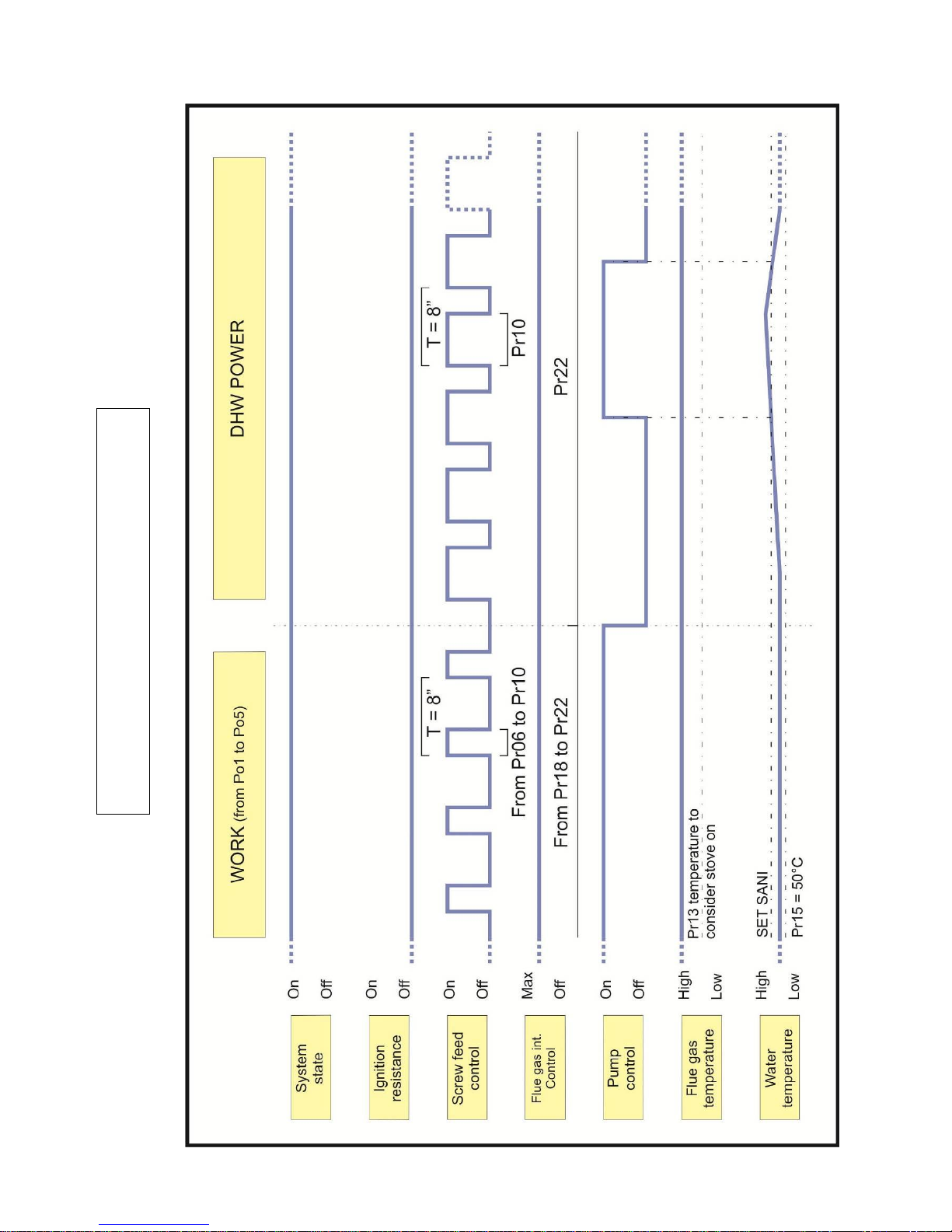
The domestic hot water is produced instantly via a double heat exchanger immersed in the water inside the
stove.
Therefore, the stove must be at temperature (60°C at least) to have domestic hot water.
Set stove in DHW power “SANI” if a large amount of domestic hot water is required.
The DHW power function “SANI” delays start-up of the heating pump at higher temperatures so that all heat
produced at such DHW temperature, is transferred.
Press SET to set the pump's start temperature when working in “SANI” and use keys 1 or 2 to change the
“SET SANI” temperature (we recommend keeping this temperature at 70–75°C). Pump will only start upon
reaching of said temperature.
We recommend re-setting stove with work power from 1 to 5 when DHW is no longer required.
If the water is particularly hard, it is indispensable to install a lime scale device at the inlet to the heat
exchanger, which must be selected on the basis of the features of the water.
Page 18
18
DHW POWER WORK PHASE
Page 19
19
7.4 Work phase with open room thermostat contact
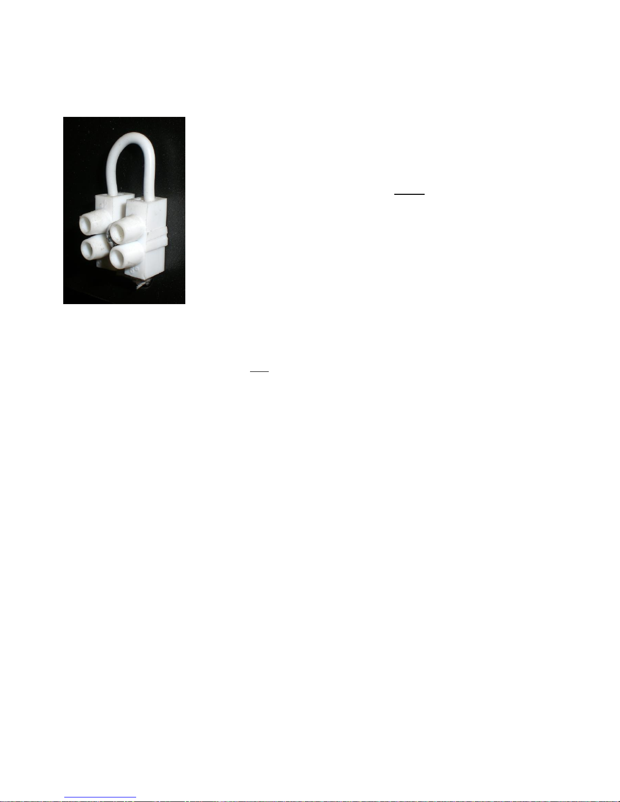
A bridge clamp is found at back of stove for connecting a room thermostat.
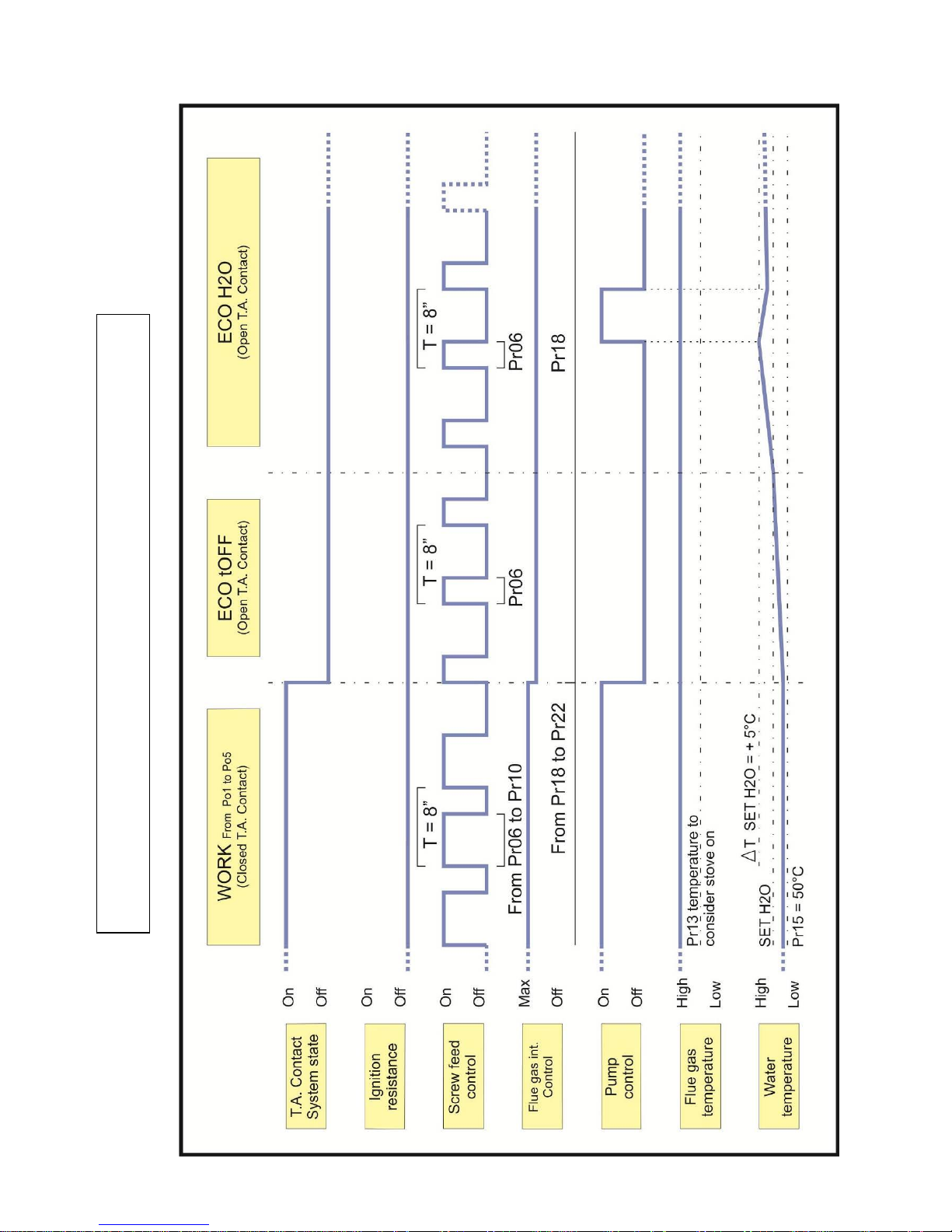
OPERATION PRINCIPLE
With open contact:
1. The stove passes directly to the “ECO TOFF” operation economy mode.
2. The stove pump switches off.
3. The temperature in the boiler increases due to thermal inertia until reaching the
temperature set on “SET H2O”, displaying “ECO H2O”.
4. The stove now automatically switches off if at least one of the following
conditions exist:
If it remains in Functioning Economy “ECO-H2O” for a time set on Pr23
(120 minute default setting).
If it exceeds temperature differential set on Pr12 (10°C default setting) or
H2O Temperature > (“SET H2O” + Pr12)
N.B.: the pump is calibrated to start with SET H2O + 5°C temperatures in all
stoves (DHW set-up).
ATTENTION: The above-described functioning on BI-FIRE MID and BI-FIRE stove only works on pellet
side. Room thermostat connection is automatically excluded with wood side on.
The stove will automatically reactivate if both of the following conditions occur:
If the contact of the room thermostat closes.
If it drops below temperature differential set on Pr12 (10°C default setting) or H2O temperature < (“SET
H2O” – Pr12).
If the above-mentioned condition occurs when the stove is still carrying out the switch off cycle, it is required to
wait until it ends.
Page 20
20
WORK PHASE WITH ROOM THERMOSTAT CONTACT
Page 21

21
7.5 BI-FIRE MID and BI-FIRE Functioning principle
The stove can function just with pellets, just with wood or with both combustion chambers on.
There are two functioning conditions:
Pellet side conditions with “PELL ON”:
it switches on automatically when the wood side switches off;
it is switched on manually;
it switches on with the chrono-thermostat.
Pellet side conditions with “PELL OFF”:
it does not switch on automatically when the wood side switches off;
it is not switched on manually;
if set with pellet side running then when it switches off, it remains off;
it switches on with the chrono-thermostat.
With the wood side on, the pellet side switches off immediately on reaching the temperature set on the “SET
H2O”.
With the wood side off, the pellet side switches off only if, after having reached ”ECO H2O” state, it exceeds
temperature differential set on the Pr12 or “ECO H2O” time set on Pr23 lapses.
ATTENTION
If temperature set on “SET H2O” is reached while pellet side performs ignition cycle, pellet side does not
immediately switch-off but only after having exceeded temperature differential set on Pr12 or after “ECO H2O”
time set on Pr23 has lapsed.
If thermo stove is working with pellet...
- Pellet only (functioning with 5 work powers, functioning economy phase, chrono-thermostat, room thermostat
function active).
- If wood side switches-on (wood fumes temperature ≥ Pr48) the pellet side switches off when the temperature
set on SET H2O is reached.
If thermo stove is working with wood...
- Wood only;
- With wood on, it is possible to switch the pellet side on manually, which will switch-off when the temperature
set on “SET H2O” is reached. To switch the pellet side on, hold key 4 down (switch-on/off);
With “PELL ON” function active:
The pellet side ignites when the wood side switches off i.e.when the flue gas temperature is lower than
150°C (Pr48) and the temperature of the water in the boiler is lower than 60°C (Pr11).
With “PELL OFF” function active:
The pellet side DOES NOT ignite when the wood side switches off i.e.when the temperature of the
fumes is lower than 150°C (Pr48) and the temperature of the water in the boiler is lower than 60°C
(Pr11).
Page 22
22
8. BOOTLOADER PROGRAMMER
8.1 Firmware loading in power board
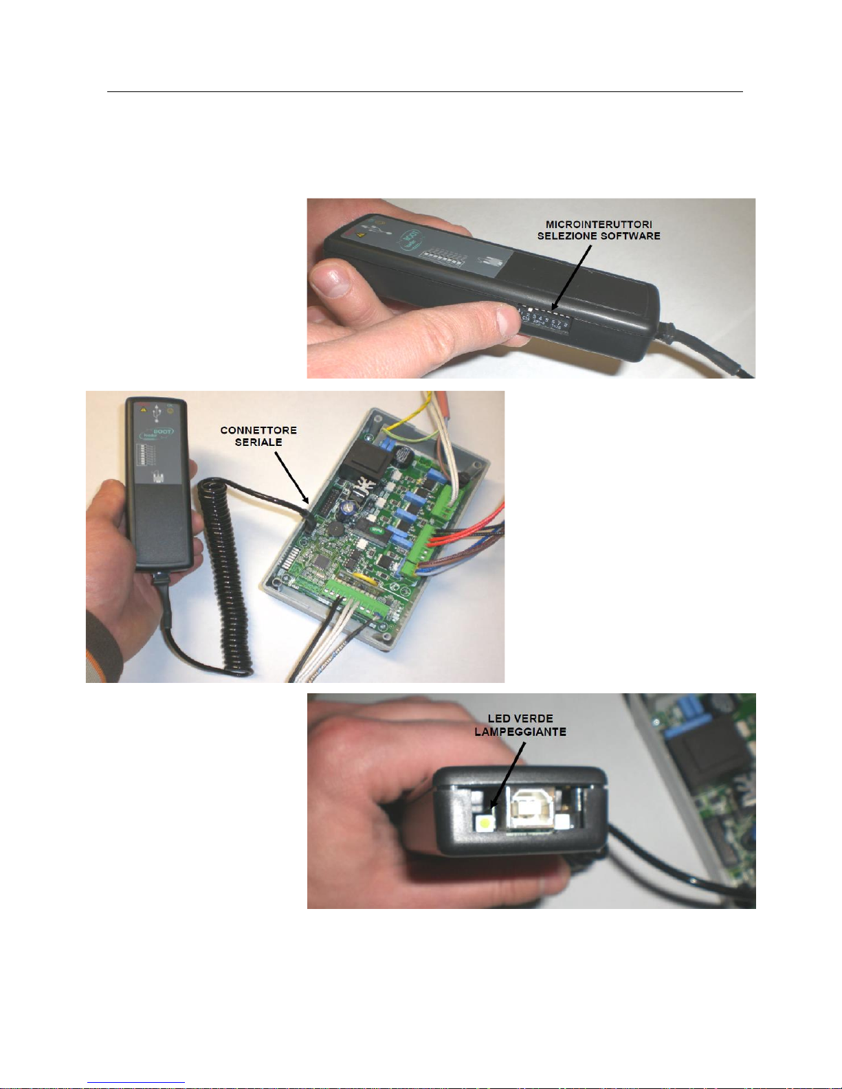
The following must be executed without USB connection.
Use the microswitches to select
the firmware to be installed in
the board.
Connect the BootLoader to the
unpowered board using only the
supplied serial cable.
Power the board and see that
the green LED flashes (if not,
repeat operation) and the red
LED remains off.
Red LED switch-on informs that
file transfer from BootLoader to
board was not successful,
repeat operation.
Disconnect the BootLoader with powered board after having correctly performed all operations, use SET key
to select user menu 4 (Ut04) and set the code of the database to be loaded on lower display (see “Power
board calibrations” and “Parameters tables”) to automatically set default parameters. Ensure the set
parameters correspond to those in the USE AND MAINTENANCE manual.
Page 23

23
9. DATABASE
A range of default settings called “Database” (recipes) can be found inside every firmware. These settings
with dependent number from the firmware version, are available but not modifiable. This to allow adapting to
only one firmware to different types of stoves, without having to manually program one parameter at a time.
Enter the key corresponding to the wanted “Database” in menu “UT04” to load the "recipes" (parameters
tables). For example, the key corresponding to the “Database” in DIVA PLUS, is “o0”; with the same
firmware loaded, the key corresponding to the “Database” in DIVA MID, is “P0”.
ATTENTION: the equipment is restored with default settings by loading a “Database” , therefore restoring all
temperature and power SET, the chrono-thermostat and the values set in other menus.
Databases may be updated. The values in the instruction manual of every equipment may not correspond to
parameters loaded in “Database”. Always check that the loaded values and those in the instructions manual
correspond.
9.1 DATABASE access keys
The “Database” of each individual equipment can be loaded thanks to the access keys in the table (see
“Parameters tables” to see the default settings).
REFERENCE
VALUE
“Database” setting key (default settings)
DIVA
o0
“Database” setting key (default settings)
STAR 14
P0
“Database” setting key (default settings)
DIVA MID
P0
“Database” setting key (default settings)
DIVA PLUS
o0
“Database” setting key (default settings)
MAGNIFIKA
o0
“Database” setting key (default settings)
PELLET FIRE PLACE 18
o0
“Database” setting key (default settings)
BI-FIRE MID
P0
“Database” setting key (default settings)
BI-FIRE
o0
Page 24
24
10. POWER BOARD CALIBRATIONS
N.B. The following description is reserved to the Authorised Technical Assistance Centre with specific
product competence. Haphazardly modifying parameters can seriously damage the equipment, persons
and the environment.
10.1 Calibrations access keys reserved to T.A.C. table
The access keys in the table allow access to all that is reserved to Technical Assistance Centre accessing
from UT04 menu (menu reserved to TAC).
REFERENCE
VALUE
General parameters technical menu access key
A9
Pre-load + additional parameters technical menu access key
B9
Ventilation + additional parameters technical menu access key
C9
Flue gas probe calibration access key
F9
10.2 How to calibrate parameters
Press SET (no. 3) 5 times.
With “temperature increase/decrease” keys (no. 1 or 2)
Set code "A9" in lower display.
Confirm with SET key (no. 3).
The parameter value can be varied using “temperature increase/decrease” keys (no. 1 or 2).
Press SET (no. 3) to confirm parameters moving onto subsequent one.
Exit calibration by pressing "switch-off" key (no. 4).
S.R.L.
SET
OK
Set
°C
1
2 3 4 6
5
Pr 01
1…
S.R.L.
SET
OK
Set
°C
1
2 3 4 6
5
Ut 04
A9
S.R.L.
SET
OK
Set
°C
1
2 3 4 6
5
Ut 04
00
Page 25
25
10.3 How to calibrate pellet flue gas probe
Follow the procedure below to calibrate the flue gas temperature probe:
Press SET (no. 3) 5 times.
Set code "F9" in lower display using “temperature increase/decrease” keys (no. 1 or 2).
Press SET (no. 3) to confirm.
The lower display value (e.g. 22) represents effective probe temperature reading. This temperature can be
varied using “temperature increase/decrease” keys (no. 1 or 2).
Make reading correspond to room temperature detected by a thermostat of reference, if operation is
performed with stove off and cold.
Press SET (no. 3) to confirm.
S.R.L.
SET
OK
Set
°C
1
2 3 4 6
5
22
S.R.L.
SET
OK
Set
°C
1
2 3 4 6
5
Ut 04
F9
Page 26

26
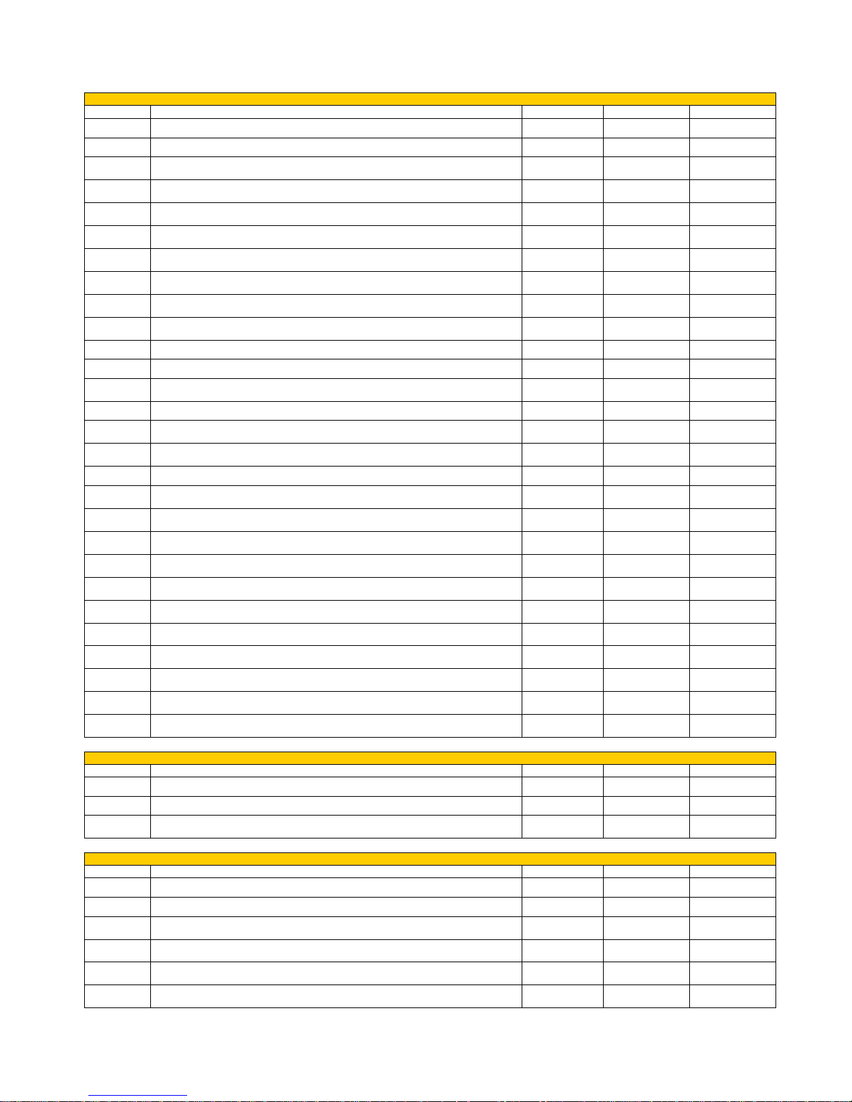
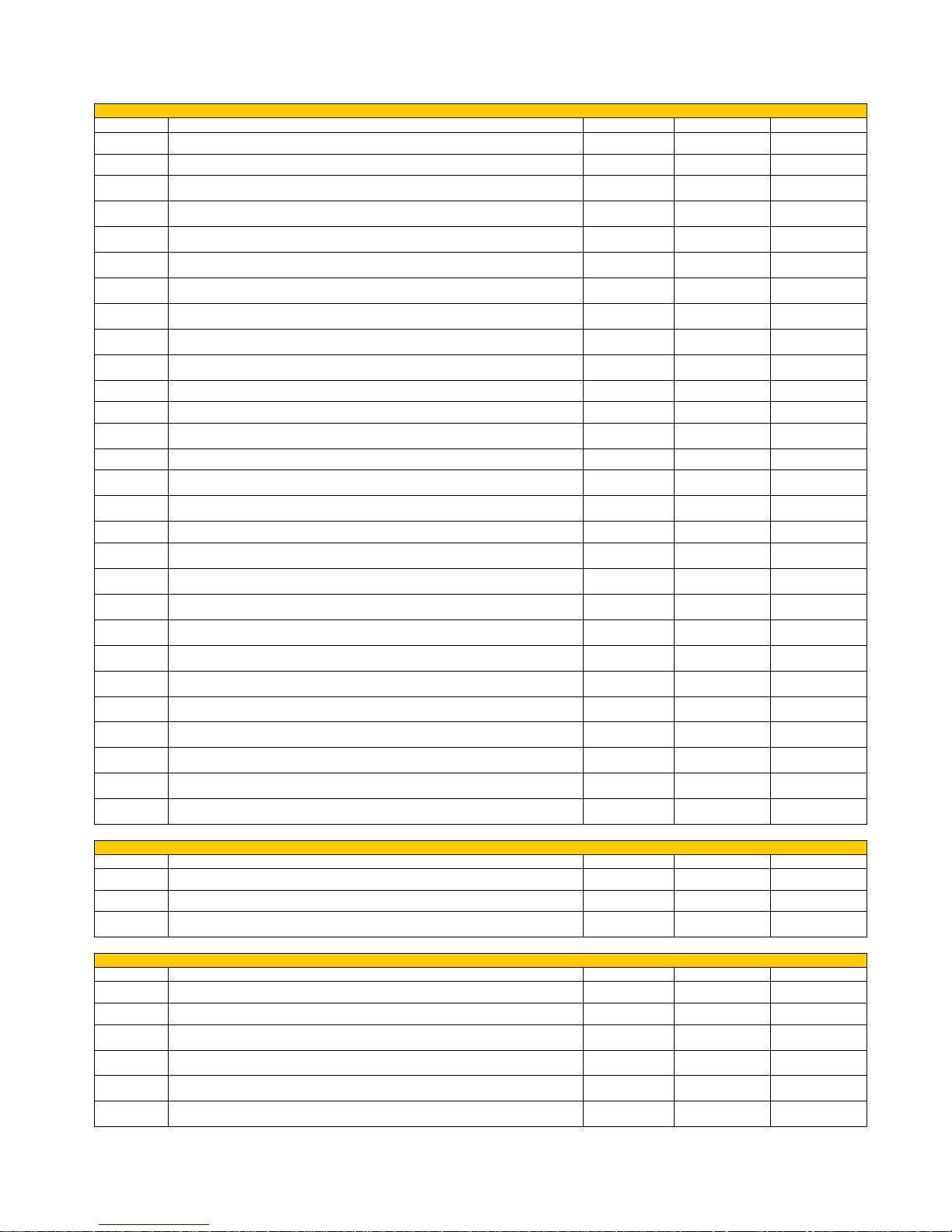
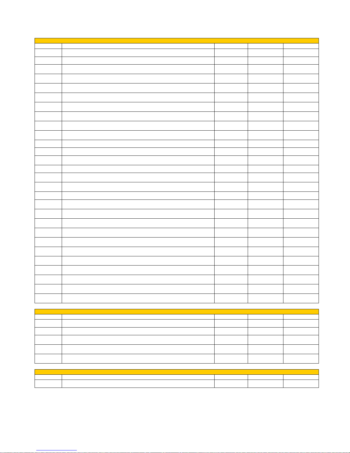
11. PARAMETERS TABLES
All parameters tables with database entered via access key are shown below. Depending on flue draught, the
parameters in red must be checked and eventually modified upon Commissioning.
DIVA FIRMWARE (DV130710_3.ENC) GENERAL PARAMETERS ACCESS KEY A9
Parameter
Description
Measurement
Value field
Database o0
Pr01
Ignition cycle maximum time “LOAD PELL”
Minutes
1 – 18
18
Pr02
Start time “FIRE ON”
Minutes
1 – 15
6
Pr03
Time interval between the two brazier cleaning operations
Minutes
2 – 255
90
Pr04
Screw feed motor reducer ON time in ignition phase “LOAD PELL”
Seconds
0.1 – 7.6
2,8
Pr05
Screw feed motor reducer ON time in start phase “FIRE ON”
Seconds
0.1 – 7.6
2,4
Pr06
Screw feed motor reducer ON time in power 1 work phase
Seconds
0.1 – 7.2
2,4
Pr07
Screw feed motor reducer ON time in power 2 work phase
Seconds
0.1 – 7.4
3,5
Pr08
Screw feed motor reducer ON time in power 3 work phase
Seconds
0.1 – 7.6
5,0
Pr09
Screw feed motor reducer ON time in power 4 work phase
Seconds
0.1 – 7.8
6,5
Pr10
Screw feed motor reducer ON time in power 5 work phase
Seconds
0.1 – 8.0
7,5
Pr11
Alarm delay
Seconds
20 – 90
30
Pr12
Temperature differential on “SET H2O” for switch-off/on
°C
2 – 20
10
Pr13
Flue gas minimum temperature to consider equipment on
°C
40 – 120
43
Pr14
Flue gas maximum temperature accepted “ECO FUMI”
°C
130 – 269
260
Pr15
Pump activation threshold
°C
40 – 80
50
Pr16
Flue gas intake device speed during ignition phase “LOAD PELL”
-
0 – 35
26
Pr17
Flue gas intake device speed during start phase “FIRE ON”
-
0 – 35
20
Pr18
Flue gas intake speed in power 1 work phase
-
0 – 35
7
Pr19
Flue gas intake speed in power 2 work phase
-
0 – 35
8
Pr20
Flue gas intake speed in power 3 work phase
-
0 – 35
9
Pr21
Flue gas intake speed in power 4 work phase
-
0 – 35
10
Pr22
Flue gas intake speed in power 5 work phase
-
0 – 35
11
Pr23
Time after which equipment switches off if it remains in “ECO H2O”
Minutes
0 – 240
120
Pr24
Brazier cleaning duration
Seconds
0 – 120
50
Pr25
PARAMETER NOT USED
-
- - Pr26
PARAMETER NOT USED
-
- - Pr27
PARAMETER NOT USED
-
-
-
Pr28
Flue gas intake device switch-off threshold (in stand-by switch-off phase)
°C
40 – 120
80
DIVA FIRMWARE (DV130710_3.ENC) PRE-LOAD PARAMETERS ACCESS KEY B9
Parameter
Description
Measurement
Value field
Database o0
Pr45
Screw feed motor reducer ON time in pre-load phase
Seconds
2 – 255
2
Pr46
Stand-by time after pre-load phase
Seconds
2 – 255
2
Pr47
Flue gas intake device speed in pre-load phase
-
1 – 35
35
Page 27

27
STAR14 FIRMWARE (DV130710_3.ENC) GENERAL PARAMETERS ACCESS KEY A9
Parameter
Description
Measurement
Value field
Database P0
Pr01
Ignition cycle maximum time “LOAD PELL”
Minutes
1 – 18
18
Pr02
Start time “FIRE ON”
Minutes
1 – 15
6
Pr03
Time interval between the two brazier cleaning operations
Minutes
2 – 255
90
Pr04
Screw feed motor reducer ON time in ignition phase “LOAD PELL”
Seconds
0.1 – 7.6
2,9
Pr05
Screw feed motor reducer ON time in start phase “FIRE ON”
Seconds
0.1 – 7.6
2,2
Pr06
Screw feed motor reducer ON time in power 1 work phase
Seconds
0.1 – 7.2
2,2
Pr07
Screw feed motor reducer ON time in power 2 work phase
Seconds
0.1 – 7.4
3,2
Pr08
Screw feed motor reducer ON time in power 3 work phase
Seconds
0.1 – 7.6
4,5
Pr09
Screw feed motor reducer ON time in power 4 work phase
Seconds
0.1 – 7.8
5,3
Pr10
Screw feed motor reducer ON time in power 5 work phase
Seconds
0.1 – 8.0
6,0
Pr11
Alarm delay
Seconds
20 – 90
30
Pr12
Temperature differential on “SET H2O” for switch-off/on
°C
2 – 20
10
Pr13
Flue gas minimum temperature to consider equipment on
°C
40 – 120
43
Pr14
Flue gas maximum temperature accepted “ECO FUMI”
°C
130 – 269
260
Pr15
Pump activation threshold
°C
40 – 80
50
Pr16
Flue gas intake device speed during ignition phase “LOAD PELL”
-
0 – 35
20
Pr17
Flue gas intake device speed during start phase “FIRE ON”
-
0 – 35
16
Pr18
Flue gas intake speed in power 1 work phase
-
0 – 35
8
Pr19
Flue gas intake speed in power 2 work phase
-
0 – 35
10
Pr20
Flue gas intake speed in power 3 work phase
-
0 – 35
12
Pr21
Flue gas intake speed in power 4 work phase
-
0 – 35
14
Pr22
Flue gas intake speed in power 5 work phase
-
0 – 35
16
Pr23
Time after which equipment switches off if it remains in “ECO H2O”
Minutes
0 – 240
120
Pr24
Brazier cleaning duration
Seconds
0 – 120
50
Pr25
PARAMETER NOT USED
-
- - Pr26
PARAMETER NOT USED
-
- - Pr27
PARAMETER NOT USED
-
- - Pr28
Flue gas intake device switch-off threshold (in stand-by switch-off phase)
°C
40 – 120
80
STAR14 FIRMWARE (DV130710_3.ENC) PRE-LOAD PARAMETERS ACCESS KEY B9
Parameter
Description
Measurement
Value field
Database P0
Pr45
Screw feed motor reducer ON time in pre-load phase
Seconds
2 – 255
2
Pr46
Stand-by time after pre-load phase
Seconds
2 – 255
2
Pr47
Flue gas intake device speed in pre-load phase
-
1 – 35
35
Page 28
28
DIVA MID FIRMWARE (DVP070513_6.ENC) GENERAL PARAMETERS ACCESS KEY A9
Parameter
Description
Measurement
Value field
Database P0
Pr01
Ignition cycle maximum time “LOAD PELL”
Minutes
1 – 18
18
Pr02
Start time “FIRE ON”
Minutes
1 – 15
2
Pr03
Time interval between the two brazier cleaning operations
Minutes
2 – 255
60
Pr04
Screw feed motor reducer ON time in ignition phase “LOAD PELL”
Seconds
0.1 – 7.6
1,6
Pr05
Screw feed motor reducer ON time in start phase “FIRE ON”
Seconds
0.1 – 7.6
2,0
Pr06
Screw feed motor reducer ON time in power 1 work phase
Seconds
0.1 – 7.2
1,6
Pr07
Screw feed motor reducer ON time in power 2 work phase
Seconds
0.1 – 7.4
2,6
Pr08
Screw feed motor reducer ON time in power 3 work phase
Seconds
0.1 – 7.6
3,8
Pr09
Screw feed motor reducer ON time in power 4 work phase
Seconds
0.1 – 7.8
5,0
Pr10
Screw feed motor reducer ON time in power 5 work phase
Seconds
0.1 – 8.0
6,2
Pr11
Alarm delay
Seconds
20 – 90
30
Pr12
Temperature differential on “SET H2O” for switch-off/on
°C
2 – 20
10
Pr13
Flue gas minimum temperature to consider equipment on
°C
40 – 120
43
Pr14
Flue gas maximum temperature accepted “ECO FUMI”
°C
130 – 269
260
Pr15
Pump activation threshold
°C
40 – 80
50
Pr16
Flue gas intake device speed during ignition phase “LOAD PELL”
-
0 – 35
14
Pr17
Flue gas intake device speed during start phase “FIRE ON”
-
0 – 35
14
Pr18
Flue gas intake speed in power 1 work phase
-
0 – 35
6
Pr19
Flue gas intake speed in power 2 work phase
-
0 – 35
9
Pr20
Flue gas intake speed in power 3 work phase
-
0 – 35
12
Pr21
Flue gas intake speed in power 4 work phase
-
0 – 35
15
Pr22
Flue gas intake speed in power 5 work phase
-
0 – 35
18
Pr23
Time after which equipment switches off if it remains in “ECO H2O”
Minutes
0 – 240
120
Pr24
Brazier cleaning duration
Seconds
0 – 120
50
Pr25
Differential on “SET H2O” to change-over three-way motorised valve
°C
2 – 30
10
Pr26
Differential on “SET SANI” to change-over three-way motorised valve
°C
2 – 30
5
Pr27
Three-way motorised valve change-over delay
Seconds
2 – 255
60
Pr28
Flue gas intake device switch-off threshold (in stand-by switch-off phase)
°C
40 – 120
80
DIVA MID FIRMWARE (DVP070513_6.ENC) PRE-LOAD PARAMETERS ACCESS KEY B9
Parameter
Description
Measurement
Value field
Database P0
Pr45
Screw feed motor reducer ON time in pre-load phase
Seconds
2 – 255
50
Pr46
Stand-by time after pre-load phase
Seconds
2 – 255
180
Pr47
Flue gas intake device speed in pre-load phase
-
1 – 35
20
DIVA MID FIRMWARE (DVP070513_6.ENC) VENTILATION PARAMETERS ACCESS KEY C9
Parameter
Description
Measurement
Value field
Database P0
Pr67
Flue gas temperature for ventilation switch-on
°C
50 – 120
75
Pr68
Fan speed at ventilation power 1
-
1 – 33
14
Pr69
Fan speed at ventilation power 2
-
1 – 33
33
Pr70
PARAMETER NOT USED
-
-
-
Pr71
PARAMETER NOT USED
-
- - Pr72
PARAMETER NOT USED
-
-
-
Page 29
29
DIVA PLUS FIRMWARE (DVP070513_6.ENC) GENERAL PARAMETERS ACCESS KEY A9
Parameter
Description
Measurement
Value field
Database o0
Pr01
Ignition cycle maximum time “LOAD PELL”
Minutes
1 – 18
18
Pr02
Start time “FIRE ON”
Minutes
1 – 15
2
Pr03
Time interval between the two brazier cleaning operations
Minutes
2 – 255
70
Pr04
Screw feed motor reducer ON time in ignition phase “LOAD PELL”
Seconds
0.1 – 7.6
2,4
Pr05
Screw feed motor reducer ON time in start phase “FIRE ON”
Seconds
0.1 – 7.6
2,8
Pr06
Screw feed motor reducer ON time in power 1 work phase
Seconds
0.1 – 7.2
2,2
Pr07
Screw feed motor reducer ON time in power 2 work phase
Seconds
0.1 – 7.4
3,5
Pr08
Screw feed motor reducer ON time in power 3 work phase
Seconds
0.1 – 7.6
5,0
Pr09
Screw feed motor reducer ON time in power 4 work phase
Seconds
0.1 – 7.8
6,3
Pr10
Screw feed motor reducer ON time in power 5 work phase
Seconds
0.1 – 8.0
7,5
Pr11
Alarm delay
Seconds
20 – 90
30
Pr12
Temperature differential on “SET H2O” for switch-off/on
°C
2 – 20
10
Pr13
Flue gas minimum temperature to consider equipment on
°C
40 – 120
43
Pr14
Flue gas maximum temperature accepted “ECO FUMI”
°C
130 – 269
260
Pr15
Pump activation threshold
°C
40 – 80
50
Pr16
Flue gas intake device speed during ignition phase “LOAD PELL”
-
0 – 35
12
Pr17
Flue gas intake device speed during start phase “FIRE ON”
-
0 – 35
12
Pr18
Flue gas intake speed in power 1 work phase
-
0 – 35
6
Pr19
Flue gas intake speed in power 2 work phase
-
0 – 35
8
Pr20
Flue gas intake speed in power 3 work phase
-
0 – 35
10
Pr21
Flue gas intake speed in power 4 work phase
-
0 – 35
12
Pr22
Flue gas intake speed in power 5 work phase
-
0 – 35
15
Pr23
Time after which equipment switches off if it remains in “ECO H2O”
Minutes
0 – 240
120
Pr24
Brazier cleaning duration
Seconds
0 – 120
50
Pr25
Differential on “SET H2O” to change-over three-way motorised valve
°C
2 – 30
10
Pr26
Differential on “SET SANI” to change-over three-way motorised valve
°C
2 – 30
5
Pr27
Three-way motorised valve change-over delay
Seconds
2 – 255
60
Pr28
Flue gas intake device switch-off threshold (in stand-by switch-off phase)
°C
40 – 120
80
DIVA PLUS FIRMWARE (DVP070513_6.ENC) PRE-LOAD PARAMETERS ACCESS KEY B9
Parameter
Description
Measurement
Value field
Database o0
Pr45
Screw feed motor reducer ON time in pre-load phase
Seconds
2 – 255
100
Pr46
Stand-by time after pre-load phase
Seconds
2 – 255
250
Pr47
Flue gas intake device speed in pre-load phase
-
1 – 35
22
DIVA PLUS FIRMWARE (DVP070513_6.ENC) VENTILATION PARAMETERS ACCESS KEY C9
Parameter
Description
Measurement
Value field
Database o0
Pr67
Flue gas temperature for ventilation switch-on
°C
50 – 120
75
Pr68
Fan speed at ventilation power 1
-
1 – 33
14
Pr69
Fan speed at ventilation power 2
-
1 – 33
33
Pr70
PARAMETER NOT USED
-
-
-
Pr71
PARAMETER NOT USED
-
- - Pr72
PARAMETER NOT USED
-
-
-
Page 30

30
MAGNIFIKA FIRMWARE (MP070509_2.ENC) GENERAL PARAMETERS ACCESS KEY A9
Parameter
Description
Measurement
Value field
Database o0
Pr01
Ignition cycle maximum time “LOAD PELL”
Minutes
1 – 18
18
Pr02
Start time “FIRE ON”
Minutes
1 – 15
6
Pr03
Time interval between the two brazier cleaning operations
Minutes
2 – 255
90
Pr04
Screw feed motor reducer ON time in ignition phase “LOAD PELL”
Seconds
0.1 – 7.6
2,8
Pr05
Screw feed motor reducer ON time in start phase “FIRE ON”
Seconds
0.1 – 7.6
2,2
Pr06
Screw feed motor reducer ON time in power 1 work phase
Seconds
0.1 – 7.2
2,4
Pr07
Screw feed motor reducer ON time in power 2 work phase
Seconds
0.1 – 7.4
3,5
Pr08
Screw feed motor reducer ON time in power 3 work phase
Seconds
0.1 – 7.6
5,0
Pr09
Screw feed motor reducer ON time in power 4 work phase
Seconds
0.1 – 7.8
6,5
Pr10
Screw feed motor reducer ON time in power 5 work phase
Seconds
0.1 – 8.0
7,5
Pr11
Alarm delay
Seconds
20 – 90
30
Pr12
Temperature differential on “SET H2O” for switch-off/on
°C
2 – 20
10
Pr13
Flue gas minimum temperature to consider equipment on
°C
40 – 120
43
Pr14
Flue gas maximum temperature accepted “ECO FUMI“
°C
130 – 269
260
Pr15
Pump activation threshold
°C
40 – 80
50
Pr16
Flue gas intake device speed during ignition phase “LOAD PELL”
-
0 – 35
30
Pr17
Flue gas intake device speed during start phase “FIRE ON”
-
0 – 35
26
Pr18
Flue gas intake speed in power 1 work phase
-
0 – 35
15
Pr19
Flue gas intake speed in power 2 work phase
-
0 – 35
17
Pr20
Flue gas intake speed in power 3 work phase
-
0 – 35
21
Pr21
Flue gas intake speed in power 4 work phase
-
0 – 35
32
Pr22
Flue gas intake speed in power 5 work phase
-
0 – 35
34
Pr23
Time after which equipment switches off if it remains in “ECO H2O”
Minutes
0 – 240
120
Pr24
Brazier cleaning duration
Seconds
0 – 120
50
Pr25
Differential on “SET H2O” to change-over three-way motorised valve
°C
2 – 30
10
Pr26
Differential on “SET SANI” to change-over three-way motorised valve
°C
2 – 30
5
Pr27
Three-way motorised valve change-over delay
Seconds
2 – 255
60
Pr28
Flue gas intake device switch-off threshold (in stand-by switch-off phase)
°C
40 – 120
80
MAGNIFIKA FIRMWARE (MP070509_2.ENC) PRE-LOAD PARAMETERS ACCESS KEY B9
Parameter
Description
Measurement
Value field
Database o0
Pr45
Screw feed motor reducer ON time in pre-load phase
Seconds
2 – 255
2
Pr46
Stand-by time after pre-load phase
Seconds
2 – 255
2
Pr47
Flue gas intake device speed in pre-load phase
-
1 – 35
35
Page 31

31
PELLET FIRE PLACE 18 FIRMWARE (PFP100709_3.ENC) GENERAL PARAMETERS ACCESS KEY A9
Parameter
Description
Measurement
Value field
Database o0
Pr01
Ignition cycle maximum time “LOAD PELL”
Minutes
1 – 18
18
Pr02
Start time “FIRE ON”
Minutes
1 – 15
4
Pr03
Time interval between the two brazier cleaning operations
Minutes
2 – 255
90
Pr04
Screw feed motor reducer ON time in ignition phase “LOAD PELL”
Seconds
0.1 – 7.6
3,0
Pr05
Screw feed motor reducer ON time in start phase “FIRE ON”
Seconds
0.1 – 7.6
2,8
Pr06
Screw feed motor reducer ON time in power 1 work phase
Seconds
0.1 – 7.2
2,6
Pr07
Screw feed motor reducer ON time in power 2 work phase
Seconds
0.1 – 7.4
3,5
Pr08
Screw feed motor reducer ON time in power 3 work phase
Seconds
0.1 – 7.6
5,0
Pr09
Screw feed motor reducer ON time in power 4 work phase
Seconds
0.1 – 7.8
6,5
Pr10
Screw feed motor reducer ON time in power 5 work phase
Seconds
0.1 – 8.0
7,5
Pr11
Alarm delay
Seconds
20 – 90
30
Pr12
Temperature differential on “SET H2O” for switch-off/on
°C
2 – 20
10
Pr13
Flue gas minimum temperature to consider equipment on
°C
40 – 120
43
Pr14
Flue gas maximum temperature accepted “ECO FUMI”
°C
130 – 269
260
Pr15
Pump activation threshold
°C
40 – 80
50
Pr16
Flue gas intake device speed during ignition phase “LOAD PELL”
-
0 – 35
22
Pr17
Flue gas intake device speed during start phase “FIRE ON”
-
0 – 35
14
Pr18
Flue gas intake speed in power 1 work phase
-
0 – 35
6
Pr19
Flue gas intake speed in power 2 work phase
-
0 – 35
8
Pr20
Flue gas intake speed in power 3 work phase
-
0 – 35
12
Pr21
Flue gas intake speed in power 4 work phase
-
0 – 35
15
Pr22
Flue gas intake speed in power 5 work phase
-
0 – 35
17
Pr23
Time after which equipment switches off if it remains in “ECO H2O”
Minutes
0 – 240
120
Pr24
Brazier cleaning duration
Seconds
0 – 120
50
Pr25
PARAMETER NOT USED
-
- - Pr26
PARAMETER NOT USED
-
-
-
Pr27
PARAMETER NOT USED
-
-
-
Pr28
Flue gas intake device switch-off threshold (in stand-by switch-off phase)
°C
40 – 120
80
PELLET FIRE PLACE 18 FIRMWARE (PFP100709_3.ENC) PRE-LOAD PARAMETERS ACCESS KEY B9
Parameter
Description
Measurement
Value field
Database o0
Pr45
Screw feed motor reducer ON time in pre-load phase
Seconds
2 – 255
130
Pr46
Stand-by time after pre-load phase
Seconds
2 – 255
110
Pr47
Flue gas intake device speed in pre-load phase
-
1 – 35
35
Page 32
32
BI-FIRE MID FIRMWARE (BF131211_6.ENC) GENERAL PARAMETERS ACCESS KEY A9
Parameter
Description
Measurement
Value field
Database P0
Pr01
Ignition cycle maximum time “LOAD PELL”
Minutes
1 – 18
18
Pr02
Start time “FIRE ON”
Minutes
1 – 15
5
Pr03
Time interval between the two brazier cleaning operations
Minutes
2 – 240
90
Pr04
Screw feed motor reducer ON time in ignition phase “LOAD PELL”
Seconds
0.1 – 7.6
2,8
Pr05
Screw feed motor reducer ON time in start phase “FIRE ON”
Seconds
0.1 – 7.6
2,2
Pr06
Screw feed motor reducer ON time in power 1 work phase
Seconds
0.1 – 7.2
2,2
Pr07
Screw feed motor reducer ON time in power 2 work phase
Seconds
0.1 – 7.4
3,3
Pr08
Screw feed motor reducer ON time in power 3 work phase
Seconds
0.1 – 7.6
4,5
Pr09
Screw feed motor reducer ON time in power 4 work phase
Seconds
0.1 – 7.8
5,8
Pr10
Screw feed motor reducer ON time in power 5 work phase
Seconds
0.1 – 8.0
6,8
Pr11
Temperature below which the pellet side switches on (on “PELL ON”)
°C
40 – 75
60
Pr12
Temperature differential on “SET H2O” for switch-off/on
°C
1 – 25
10
Pr13
Flue gas minimum temperature to consider equipment on
°C
40 – 120
56
Pr14
Flue gas maximum temperature accepted “ECO FUMI”
°C
130 – 270
260
Pr15
Pump activation threshold
°C
48 – 80
55
Pr16
Flue gas intake device speed during ignition phase “LOAD PELL”
-
0 – 35
30
Pr17
Flue gas intake device speed during start phase “FIRE ON”
-
0 – 35
26
Pr18
Flue gas intake speed in power 1 work phase
-
0 – 35
8
Pr19
Flue gas intake speed in power 2 work phase
-
0 – 35
12
Pr20
Flue gas intake speed in power 3 work phase
-
0 – 35
18
Pr21
Flue gas intake speed in power 4 work phase
-
0 – 35
23
Pr22
Flue gas intake speed in power 5 work phase
-
0 – 35
27
Pr23
Time after which equipment switches off if it remains in “ECO H2O”
Minutes
0 – 120
120
Pr24
Brazier cleaning duration
Seconds
0 – 120
50
Pr25
Differential on “SET H2O” to change-over three-way motorised valve
°C
2 – 30
10
Pr26
Differential on “SET SANI” to change-over three-way motorised valve
°C
2 – 30
5
Pr27
Three-way motorised valve change-over delay
Seconds
2 – 255
60
Pr28
Flue gas intake device switch-off threshold (in stand-by switch-off phase)
°C
40 – 120
80
BI-FIRE MID FIRMWARE (BF131211_6.ENC) PRE-LOAD PARAMETERS + ADDITIONAL PARAMETERS ACCESS KEY B9
Parameter
Description
Measurement
Value field
Database P0
Pr45
Screw feed motor reducer ON time in pre-load phase
Seconds
2 – 255
2
Pr46
Stand-by time after pre-load phase
Seconds
2 – 255
2
Pr47
Flue gas intake device speed in pre-load phase
-
1 – 35
35
Pr48
Wood flue gas minimum temperature to consider the wood side on
°C
80 – 509
150
Pr49
Recirculation pump activation threshold
°C
31 – 80
50
BI-FIRE MID FIRMWARE (BF131211_6.ENC) ADDITIONAL PARAMETERS ACCESS KEY C9
Parameter
Description
Measurement
Value field
Database P0
Pr55
Time for pellet side switch-on if the conditions exist after wood side switch-off
Minutes
1 – 50
1
Page 33
33
BI-FIRE FIRMWARE (BF131211_6.ENC) GENERAL PARAMETERS ACCESS KEY A9
Parameter
Description
Measurement
Value field
Database o0
Pr01
Ignition cycle maximum time “LOAD PELL”
Minutes
1 – 18
18
Pr02
Start time “FIRE ON”
Minutes
1 – 15
5
Pr03
Time interval between the two brazier cleaning operations
Minutes
2 – 240
90
Pr04
Screw feed motor reducer ON time in ignition phase “LOAD PELL”
Seconds
0.1 – 7.6
2,8
Pr05
Screw feed motor reducer ON time in start phase “FIRE ON”
Seconds
0.1 – 7.6
2,4
Pr06
Screw feed motor reducer ON time in power 1 work phase
Seconds
0.1 – 7.2
2,4
Pr07
Screw feed motor reducer ON time in power 2 work phase
Seconds
0.1 – 7.4
3,5
Pr08
Screw feed motor reducer ON time in power 3 work phase
Seconds
0.1 – 7.6
5,0
Pr09
Screw feed motor reducer ON time in power 4 work phase
Seconds
0.1 – 7.8
6,5
Pr10
Screw feed motor reducer ON time in power 5 work phase
Seconds
0.1 – 8.0
7,5
Pr11
Temperature below which the pellet side switches on (on “PELL ON”)
°C
40 – 75
60
Pr12
Temperature differential on “SET H2O” for switch-off/on
°C
1 – 25
10
Pr13
Flue gas minimum temperature to consider equipment on
°C
40 – 120
56
Pr14
Flue gas maximum temperature accepted “ECO FUMI”
°C
130 – 270
260
Pr15
Pump activation threshold
°C
48 – 80
55
Pr16
Flue gas intake device speed during ignition phase “LOAD PELL”
-
0 – 35
30
Pr17
Flue gas intake device speed during start phase “FIRE ON”
-
0 – 35
26
Pr18
Flue gas intake speed in power 1 work phase
-
0 – 35
10
Pr19
Flue gas intake speed in power 2 work phase
-
0 – 35
14
Pr20
Flue gas intake speed in power 3 work phase
-
0 – 35
20
Pr21
Flue gas intake speed in power 4 work phase
-
0 – 35
25
Pr22
Flue gas intake speed in power 5 work phase
-
0 – 35
32
Pr23
Time after which equipment switches off if it remains in “ECO H2O”
Minutes
0 – 120
120
Pr24
Brazier cleaning duration
Seconds
0 – 120
50
Pr25
Differential on “SET H2O” to change-over three-way motorised valve
°C
2 – 30
10
Pr26
Differential on “SET SANI” to change-over three-way motorised valve
°C
2 – 30
5
Pr27
Three-way motorised valve change-over delay
Seconds
2 – 255
60
Pr28
Flue gas intake device switch-off threshold (in stand-by switch-off phase)
°C
40 – 120
80
BI-FIRE FIRMWARE (BF131211_6.ENC) PRE-LOAD PARAMETERS + ADDITIONAL PARAMETERS ACCESS KEY B9
Parameter
Description
Measurement
Value field
Database o0
Pr45
Screw feed motor reducer ON time in pre-load phase
Seconds
2 – 255
2
Pr46
Stand-by time after pre-load phase
Seconds
2 – 255
2
Pr47
Flue gas intake device speed in pre-load phase
-
1 – 35
35
Pr48
Wood flue gas minimum temperature to consider the wood side on
°C
80 – 509
150
Pr49
Recirculation pump activation threshold
°C
31 – 80
50
BI-FIRE FIRMWARE (BF131211_6.ENC) ADDITIONAL PARAMETERS ACCESS KEY C9
Parameter
Description
Measurement
Value field
Database o0
Pr55
Time for pellet side switch-on if the conditions exist after wood side switch-off
Minutes
1 – 50
1
Page 34

34
12. PARAMETERS EXPLANATION
Pr01 Ignition cycle maximum time “LOAD PELL”
Allows setting maximum time granted for ignition phase. The flue gas temperature set on Pr13 must be
reached within the limit time set in this parameter to change to work phase. if sufficient flue gas temperature
(Pr13) is reached change to work phase is immediate, therefore we recommend keeping this parameter set at
maximum value 18' (default setting). It is not necessary for all time set in this parameter to lapse for change to
work phase.
Pr02 Start time “FIRE ON”
Allows setting duration time of the “FIRE ON” phase. The “FIRE ON” phase is used to evenly ignite all the
unburnt pellet during previous “LOAD PELL” phase. Duration of this parameter can be increased if required
when using "hard" pellet (or dark) difficult to burn, to give all accumulated pellet more time to ignite.
Parameters Pr05 and Pr17 linked to this parameter can be increased or decreased.
Pr03 Time interval between the two brazier cleaning operations
Allows setting time between the two brazier cleaning operations. The parameter can be increased or
decreased based on burnt pellet. It often depends on its quality and hardness. It is essential to reduce the set
value to increase brazier cleaning frequency with "hard" (or dark) pellet. The brazier cleaning duration is set on
parameter Pr12 which relates to this parameter.
Pr04 Screw feed motor reducer ON time in ignition phase “LOAD PELL”
Allows setting the motor reducer ignition time (with 8 second intervals) when the equipment is working in
“LOAD PELL” phase, following pre-load phase (if present).
Pr05 Screw feed motor reducer ON time in start phase “FIRE ON”
Allows setting the motor reducer ignition time (with 8 second intervals) when the equipment is working in
“FIRE ON” phase.
Pr06 Screw feed motor reducer ON time in power 1 work phase
Allows setting the motor reducer ignition time (with 8 second intervals) when the equipment is working in
POWER 1.
Pr07 Screw feed motor reducer ON time in power 2 work phase
Allows setting the motor reducer ignition time (with 8 second intervals) when the equipment is working in
POWER 2.
Pr08 Screw feed motor reducer ON time in power 3 work phase
Allows setting the motor reducer ignition time (with 8 second intervals) when the equipment is working in
POWER 3.
Pr09 Screw feed motor reducer ON time in power 4 work phase
Allows setting the motor reducer ignition time (with 8 second intervals) when the equipment is working in
POWER 4.
Pr10 Screw feed motor reducer ON time in power 5 work phase
Allows setting the motor reducer ignition time (with 8 second intervals) when the equipment is working in
POWER 5. This parameter also relates to motor reducer ignition time (with 8 second intervals) when the
equipment is working in “SANI” POWER.
Pr11 Alarm delay
Allows setting time after which a possible detected alarm is signalled. The parameter is not normally modified.
Pr11 Temperature below which the pellet side switches on (on “PELL ON”)
Allows setting the water temperature threshold below which the pellet side automatically switches on
following wood side switch-off (see “BI-FIRE MID and BI-FIRE Functioning principle”). This parameter
can be increased or decreased if necessary to anticipate or delay pellet side ignition.
Page 35

35
Pr12 Temperature differential on “SET H2O” and “SET SANI” for switch-off/on
Allows setting temperature differential on “SET H2O” and “SET SANI” for equipment switch-off and re-ignition.
The equipment automatically switches off placing itself in “STOP FIRE” stand-by position once the
temperature differential (or “SET H2O” or “SET SANI” + Pr12) is exceeded. It will automatically re-ignite below
the temperature differential (in this case only on “SET H2O” or “SET H2O” – Pr12). This parameter can be
increased or decreased if necessary to anticipate or delay equipment switch-off. To avoid continuous switchoff and re-ignition, it is advised not to excessively decrease this value.
Pr13 Flue gas minimum temperature to consider equipment on
Allows setting the flue gas minimum temperature value to consider equipment on. The equipment changes to
work phase if the flue gas temperature set on this parameter is reached within ignition time (value set on
Pr01); if not, it goes in “NO PELL” or “NO FIRE” alarm. To avoid risk of not reaching sufficient temperature in
ignition phase, it is advised not to excessively increase this parameter value; vice-versa, to avoid the
temperature of the water inside the boiler's body heating the flue gas so that the equipment goes to work
phase (flue gas temperature > Pr13) without pellet igniting, do not excessively decrease this parameter value.
The parameter is not normally changed; however, should it be necessary to do so, the set value goes from 4555°C. Below the temperature set in this parameter with manual equipment switch-off “OFF”, the flue gas intake
device electric power supply is also interrupted during switch-off phase.
Pr14 Flue gas maximum temperature accepted “ECO FUMI”
Allows setting the accepted flue gas maximum temperature. The equipment goes to safe work phase called
“ECO FUMI” when reached. The equipment automatically goes to POWER 1 during this phase. The
parameter is not normally modified.
Pr15 Pump activation threshold
Allows setting the system's pump start temperature. The forming of condensate inside the boiler body affecting
its duration and correct equipment functioning can be avoided by increasing this parameter value but not
decrease it.
Pr16 Flue gas intake device speed during ignition phase “LOAD PELL”
Allows setting the flue gas intake device speed when the equipment is working in “LOAD PELLET” phase
(excluding previous pre-load phase if present). If using a difficult to burn "hard" (or dark) pellet, this parameter
value can be increased. The same must also be increased/decreased depending on flue draught.
Pr17 Flue gas intake device speed during start phase “FIRE ON”
Allows setting flue gas intake device speed (revs/min) when equipment is working in “FIRE ON” phase. If
using a difficult to burn "hard" (or dark) pellet, this parameter value can be increased. The same must also be
increased/decreased depending on flue draught.
Pr18 Flue gas intake speed in power 1 work phase
Allows setting flue gas intake device speed when equipment is working in POWER 1. If using a difficult to burn
"hard" (or dark) pellet, this parameter value can be increased. The same must also be increased/decreased
depending on flue draught.
Pr19 Flue gas intake speed in power 2 work phase
Allows setting flue gas intake device speed when equipment is working in POWER 2. If using a difficult to burn
"hard" (or dark) pellet, this parameter value can be increased. The same must also be increased/decreased
depending on flue draught.
Pr20 Flue gas intake speed in power 3 work phase
Allows setting flue gas intake device speed when equipment is working in POWER 3. If using a difficult to burn
"hard" (or dark) pellet, this parameter value can be increased. The same must also be increased/decreased
depending on flue draught.
Page 36

36
Pr21 Flue gas intake speed in power 4 work phase
Allows setting flue gas intake device speed when equipment is working in POWER 4. If using a difficult to burn
"hard" (or dark) pellet, this parameter value can be increased. The same must also be increased/decreased
depending on flue draught.
Pr22 Flue gas intake speed in power 5 work phase
Allows setting flue gas intake device speed when equipment is working in POWER 5. If using a difficult to burn
"hard" (or dark) pellet, this parameter value can be increased. The same must also be increased/decreased
depending on flue draught. This parameter also relates to flue gas intake device on models set-up with DHW,
when equipment is working in “SANI” POWER.
Pr23 Time after which equipment switches off if it remains in “ECO H2O”
Allows setting time after which equipment switches off once "SET H2O" set temperature is reached.
Anticipated switch-off occurs without passing of time set on this parameter if the water temperature exceeds
Pr12 within this time. This parameter can be increased or decreased if necessary to anticipate or delay
equipment switch-off. To avoid continuous switch-off and re-ignition, it is advised not to excessively decrease
this value (value below 10').
Pr24 Brazier cleaning duration
Allows setting brazier cleaning duration time that happens after a time interval set on parameter Pr03. The
wording “COOL FIRE” appears on display during cleaning phase. The value to be set depends on burnt pellet
quality and hardness. It is essential to increase the set value to increase brazier cleaning duration with "hard"
(or dark) pellet. The factory setting (see database) is normally increased by about 10"/20". Excessive cleaning
duration increase can lead to total brazier emptying with consequent going off of the flame during this phase. It
is advised not to excessively increase this value but to increase brazier cleaning frequency (by decreasing
time set on parameter Pr03).
Pr25 Differential on “SET H2O” to change-over three-way motorised valve
Allows setting temperature differential on “SET H2O” (working from power 1 to power 5) for three-way
motorised valve assembled on DHW, change-over.
The three-way motorised valve changes to automatic once temperature differential is exceeded (or H2O
temperature > (SET H2O - Pr25)), placing itself in "open pellet stove DHW circuit" and, consequently, in
"closed coupled boiler DHW circuit". It will automatically change back (taking itself back to "closed pellet stove
DHW circuit" position and, consequently, to "open coupled boiler DHW circuit") only below temperature
differential (or H2O temperature < (SET H2O - Pr25)).
This parameter can be increased or decreased if necessary to anticipate or delay 3-way valve exchange. To
avoid its continuous exchanges, it is advised not to excessively decrease this value. Change-over happens
after time set on parameter Pr27.
Pay attention as the three-way valve exchange temperature also varies when varying "SET H2O" temperature.
Example:
WORK POWER: from 1 to 5
SET H2O = 60°C
Pr25 = 5°C
Pr27 = 60”
The valve opens in pellet thermo stove DHW circuit after 60" from reaching 56°C.
It closes after 60" if temperature drops below 55°C (at 54°C).
Pr25 PARAMETER NOT USED
The parameter is not used in some products.
Pr26 Differential on “SET SANI” to change-over three-way motorised valve
Allows setting temperature differential on “SET SANI” (working in DHW power) for three-way motorised valve
assembled on DHW, change-over.
The three-way motorised valve changes to automatic once temperature differential is exceeded (or H2O
temperature > (SET SANI - Pr25)), placing itself in "open pellet stove DHW circuit" and, consequently, in
"closed coupled boiler DHW circuit". It will automatically change back (taking itself back to "closed pellet stove
DHW circuit" position and, consequently, to "open coupled boiler DHW circuit") only below temperature
differential (or H2O temperature < (SET SANI - Pr25)).
This parameter can be increased or decreased if necessary to anticipate or delay 3-way valve exchange. To
avoid its continuous exchanges, it is advised not to excessively decrease this value. Change-over happens
Page 37

37
after time set on parameter Pr27.
Pay attention as the three-way valve exchange temperature also varies when varying "SET SANI"
temperature.
Example:
WORK POWER: SANI
SET SANI = 70°C
Pr26 = 10°C
Pr27 = 60”
The valve opens in pellet thermo stove DHW circuit after 60" from reaching 61°C.
It closes after 60" if temperature drops below 60°C (at 59°C).
Pr26 PARAMETER NOT USED
The parameter is not used in some products.
Pr27 Three-way motorised valve change-over delay
Allows setting time after which three-way motorised valve change-over happens if the conditions on
parameters Pr25 and Pr26 exist. The parameter is not normally modified. To avoid its continuous three-way
valve exchanges, jeopardising its duration, it is advised not to excessively decrease this value.
Pr27 PARAMETER NOT USED
The parameter is not used in some products.
Pr28 Flue gas intake device switch-off threshold (in stand-by switch-off phase)
Only valid with automatic switch-off “STOP FIRE”, this parameter allows setting the flue gas temperature
minimum threshold below which the flue gas intake devices switches off. The parameter is not normally
modified.
Pr45 Screw feed motor reducer ON time in pre-load phase
Allows setting motor reducer ignition time during initial pre-load phase in ignition. This phase is part of the
entire ignition phase “LOAD PELL”. The motor reducer remains continuously on during this phase to allow
loading sufficient pellet to cover the ignition resistance. If necessary, this parameter can be increased or
decreased. The pellet must not excessively cover resistance during pre-load to avoid "popping" effect due to
excessive pellet during ignition phase; load depends on size of burnt pellet. Parameters Pr46 and Pr47 linked
to this parameter can be increased or decreased.
Pr46 Stand-by time after pre-load phase
Allows setting a time during which motor reducer remains off after initial pre-load phase. This parameter can
be increased or decreased to anticipate/delay change to subsequent intermittent pellet load phase during
“LOAD PELL” ignition phase.
Pr47 Flue gas intake device speed in pre-load phase
Allows setting flue gas intake device speed when equipment is working in pellet pre-load in brazier phase. If
using a difficult to burn "hard" (or dark) pellet, this parameter value can be increased. The same must also be
increased/decreased depending on flue draught.
Pr48 Wood flue gas minimum temperature to consider the wood side on
Allows setting the flue gas minimum temperature value (wood side) to consider wood combustion chamber on.
To avoid risk of not reaching sufficient flue gas temperature to consider wood side on, it is advised not to
excessively increase this parameter value; vice-versa, to avoid wood side being detected as on even if it is not
(or with coal on only), do not excessively decrease it. The parameter is not normally varied.
Pr49 Recirculation pump activation threshold
Allows setting the recirculation pump start temperature. The parameter is not normally modified.
Page 38

38
Pr55 Time for pellet side switch-on if the conditions exist after wood side switch-off
Allows setting the time (minutes) after which the pellet side automatically switches on following wood side
switch-off (see “BI-FIRE MID and BI-FIRE Functioning principle”). This parameter can be increased or
decreased if necessary to anticipate or delay pellet side ignition.
Pr67 Flue gas temperature for ventilation switch-on
Allows setting the flue gas temperature for hot air fans switch-on; only in set-up models the fans switch-on only
if set at work speed different from "0" (settable speeds: 0, 1, 2, 3). The parameter is not normally modified.
Pr68 Fan speed at ventilation power 1
Allows setting hot air fans speed at ventilation power 1 in the set-up models. The parameter is not normally
modified.
Pr69 Fan speed at ventilation power 2
Allows setting hot air fans speed at ventilation power 2 in the set-up models. The parameter is not normally
modified.
Pr70 PARAMETER NOT USED
The parameter is not used in some products.
Pr71 PARAMETER NOT USED
The parameter is not used in some products.
Pr72 PARAMETER NOT USED
The parameter is not used in some products.
Page 39
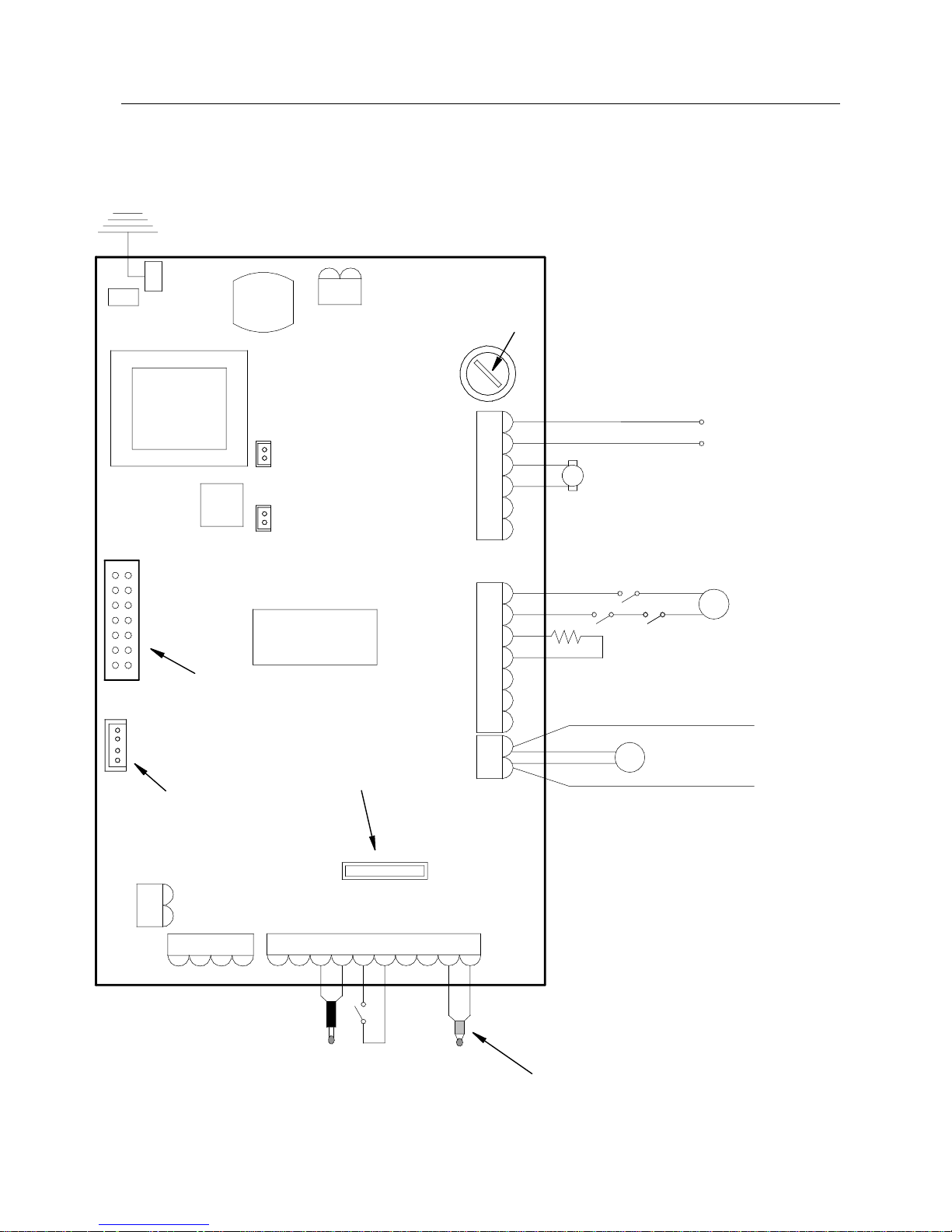
39
13. WIRING DIAGRAMS
13.1 DIVA – STAR14 wiring diagram (Motherboard I023)
TRANSFORMER
IGNITION RELAY
EARTH
FLUE GAS
EXTRATION
INTAKE DEVIC E
PHASE
NEUTRAL
230Vac
NETWORK
BROWN
BLUE
M
SCREW FEED
MOTOR REDUCER
ALF
ALP
IGNITION
RESISTANCE
ROOM
THERMOSTA
T
CN4
CN8
CN9
CN13
CN5
CN1
CN2
CN7
PELLET SIDE
FUMES PROBE
N.PEL.
N.H20
N.AMB.
TERM.
BLUE
RED
WATER
PROBE
-TC1+
ACC.
COC.
N
F
SCAM.
FUMI
N
AL1AL2
IMPORTANT: DO NOT
INVERT TH E POSITION
OF THE WIRES
CN6
DISSIPATER
N
F
SCAM
FUMI
CN15
FUSE
4A 5X20
CN12
CN10
BOARD I023
CN14
DISPLAY
CONNEC TOR
WIRES (WITH 220V)
CONTROL OF ANT
COUPLED
BOILER
SCAM.
AUX
ALT
P
HEATING SYSTEM
PUMP
SAFETY DEVICES KEY:
ALP = DOOR CLOSING MICRO SWITCH
ALF = FLUE GAS PRESSURE SWITCH
ALT = MANUAL RE-ARM THERMOSTAT
CONNECTOR
FOR SERIAL OR
EXPANSION BOARD
I055 CONNECTION
CONNECT A RELAY AT SET-UP WIRES OUTLE T
(POWERED WITH 220V VOLTAGE) FOR ELECTRIC
CONNECTION TO COUPLED BOILER.
CR2032 3Volts
CHRONO-THERMOSTAT
CLOCK BATTERY
Page 40
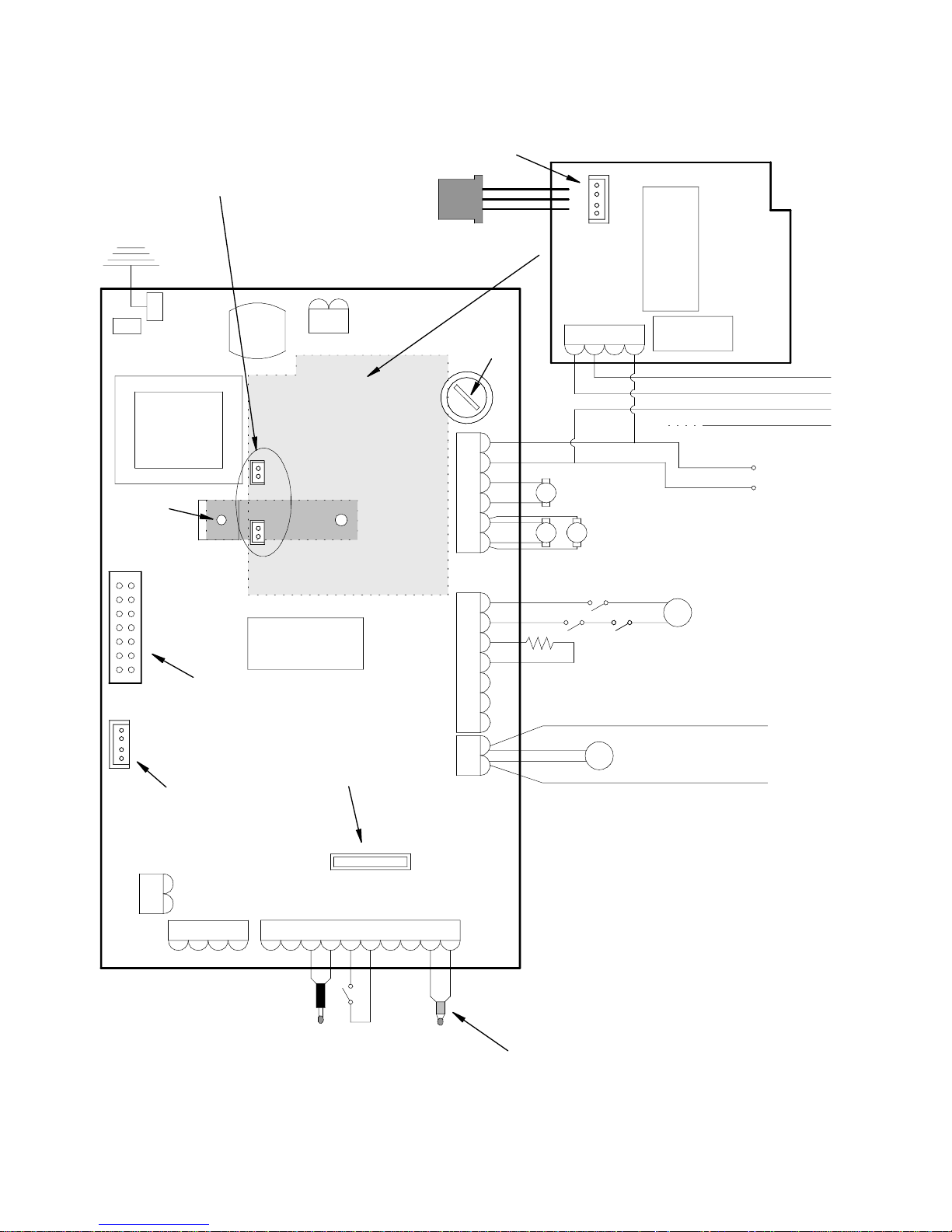
40
13.2 DIVA MID – DIVA PLUS wiring diagram (Motherboard I023)
TRANSFORMER
IGNITION RELAY
EARTH
FLUE GAS
EXTRATION
INTAKE DEVICE
PHASE
NEUTRAL
230Vac
NETWORK
BROWN
BLUE
M
SCREW FEED
MOTOR REDUCER
ALF ALP
IGNITION
RESISTANCE
ROOM
THERMOSTA
T
CN4
CN8
CN9
CN13
CN5
CN1
CN2
CN3
CN7
PELLET SIDE
FUMES PROBE
FUSE
3,15A 5X20
N.PEL.
N.H20
N.AMB.
TERM.
BLUE
RED
WATER
PROBE
-TC1+
ACC. COC.
N
F
SCAM.
FUMI
N
AL1AL2
IMPORTANT: DO NOT
INVERT THE PO SITION
OF THE WIRES
CN6
CN6
RELAY
EXPANSION BOARD I055
FOR 3-WAY VALVE (OPTI ONAL)
DISSIPATER
N
F
SCAM
FUMI
CN15
FUSE
4A 5X20
connector to C N13
on board I023
New serial connection
EXPANSION BOARD I055 CONNECTED TO I023
WITH CONNECTORS CN10 AND CN12
CN12
CN10
FASTENING
SCREWS
BROWN ON CABLE
BLACK ON CABLE
BLUE ON CABLE
GREEN/YELLOW EARTH ON CAB LE
BOARD I023
CN14
DISPLAY
CONNECTOR
WIRES ( WITH 220V)
CONTROL OF ANT
COUPLED BOILER
4 x 0,75 CABLE (OPTIONAL)
FOR CONNECTION OF THE
MOTORISED 3-WAY VALVE
SCAM.
AUX
ALT
P
HEATING SYST EM
PUMP
SAFETY DEVICES KEY:
ALP = DOOR CLOSING MICRO SWITCH
ALF = FLUE GAS PRESSURE SWITCH
ALT = MANUAL RE-ARM THERMOSTAT
CONNECTOR
FOR SERIAL OR
EXPANSION BOARD
I055 CONNECTION
CONNECT A RELAY AT SET-UP WIRES OUTLET
(POWERED WITH 220V VOLTAGE) FOR ELECTRIC
CONNECTION TO COUPLED BOILER.
CR2032 3Volts
CHRONO-THERMOSTAT
CLOCK BATTERY
THREE-WAY CONNECTION KEY:
BLUE = COMMON
BLACK = PHASE OPENING
BROWN = PHASE CLOSING
YELLOW/GREEN = EARTH MASS
SX
DX
HOT AIR
CENTRIFUGA L
FANS (OPTIONAL)
Page 41
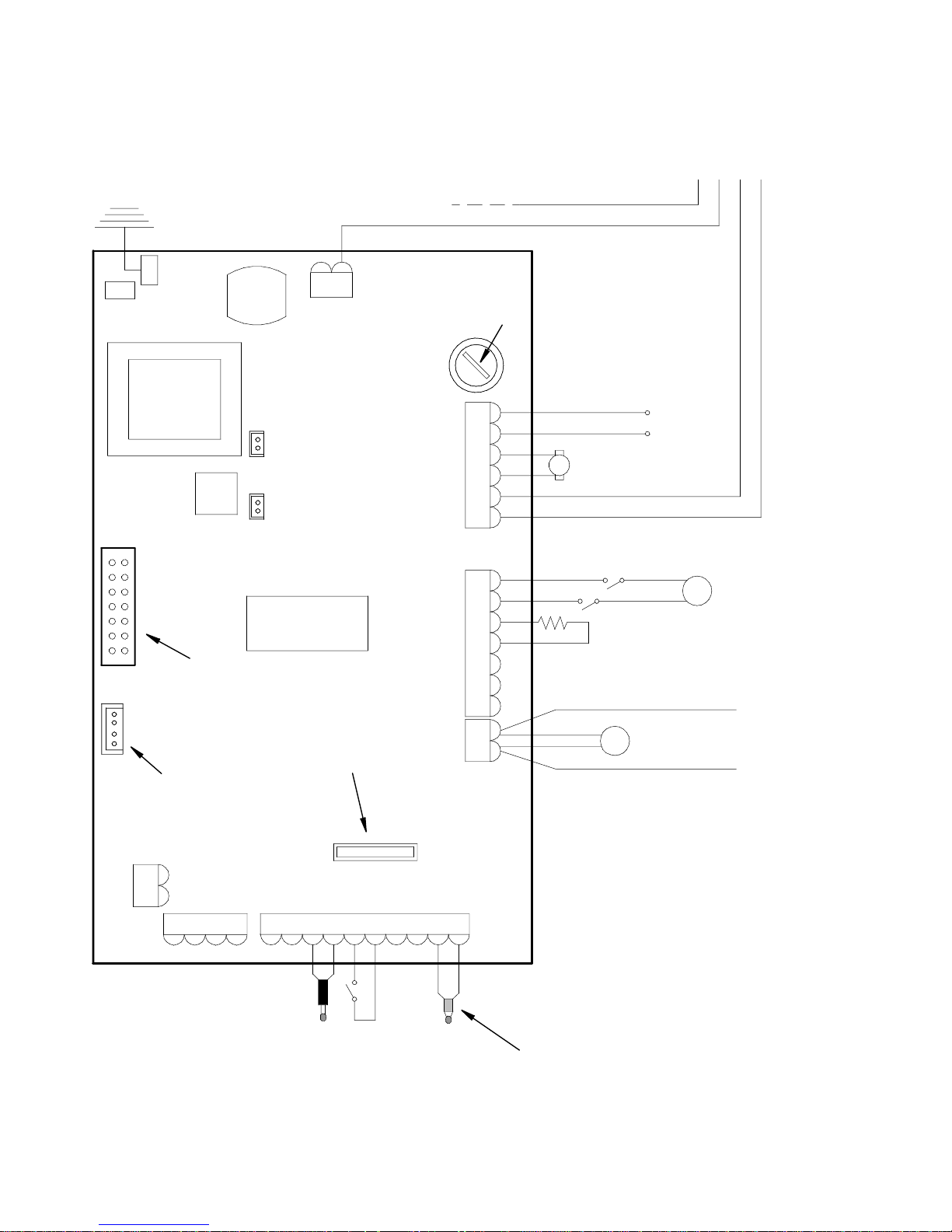
41
13.3 MAGNIFIKA wiring diagram (Motherboard I023)
TRANSFORMER
IGNITION RELAY
EARTH
FLUE GAS EXTRATION
INTAKE DEVICE
PHASE
NEUTRAL
230Vac
NETWORK
BROWN
BLUE
M
SCREW FEED
MOTOR REDUCER
ALF
IGNITION
RESISTANCE
ROOM
THERMOSTA
T
CN4
CN8
CN9
CN13
CN5
CN1
CN2
CN7
PELLET SIDE
FUMES PROBE
N.PEL. N.H20
N.AMB.
TERM.
BLUE
RED
WATER
PROBE
-TC1+
ACC. COC.
N
F
SCAM.
FUMI
N
AL1AL2
IMPORTANT: DO NOT
INVERT TH E POSITION
OF THE WIRES
CN6
DISSIPATER
N
F
SCAM
FUMI
CN15
FUSE
4A 5X20
CN12
CN10
BOARD I023
CN14
DISPLAY
CONNECTOR
WIRES (WITH 220V)
CONTROL OF ANT
COUPLED
BOILER
SCAM.
AUX
ALT
P
HEATING SYSTEM
PUMP
SAFETY DEVICES KEY:
ALF = FLUE GAS PRESSURE SWITCH
ALT = MANUAL RE-ARM THERMOSTAT
CONNECTOR
FOR SERIAL OR
EXPANSION BOARD
I055 CONNECTION
CONNECT A RELAY A T SET-UP WIRES OUTLET
(POWERED WITH 220V VOLTAGE) FOR ELECTRIC
CONNECTION TO COUPLED BOILER.
CR2032 3Volts
CHRONO-THERMOSTA T
CLOCK BATTERY
BROWN ON CABLE
BLACK ON CABLE
BLUE ON CA BLE
GREEN/YELLOW EARTH ON CALBE
4 x 0,75 C ABLE (OPTIONAL)
FOR CONNECTION OF THE
MOTORIS ED 3-WAY VALVE
THREE-WAY CONNECTION KEY:
BLUE = COMMON
BLACK = PHASE OPENING
BROWN = PHASE CLOSING
YELLOW/GREEN = EARTH MASS
Page 42
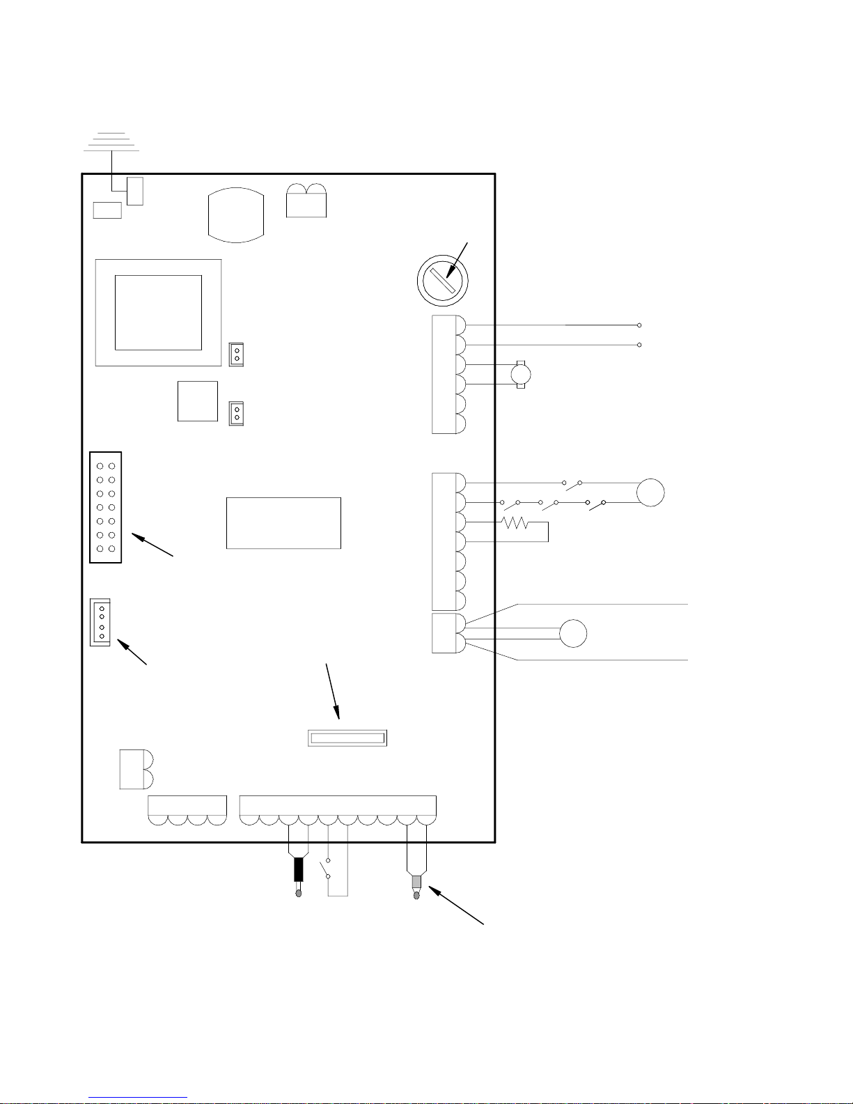
42
13.4 PELLET FIRE PLACE 18 wiring diagram (Motherboard I023)
TRANSFORMER
IGNITION RELAY
EARTH
FLUE GAS
EXTRATION
INTAKE DEVICE
PHASE
NEUTRAL
230Vac
NETWORK
BROWN
BLUE
M
SCREW FEED
MOTOR REDUCER
ALT ALA
IGNITION
RESISTANCE
ROOM
THERMOSTA
T
CN4
CN8
CN9
CN13
CN5
CN1
CN2
CN7
PELLET SIDE
FUMES PROBE
N.PEL. N.H20
N.AMB.
TERM.
BLUE
RED
WATER
PROBE
-TC1+
ACC.
COC.
N
F
SCAM.
FUMI
N
AL1AL2
IMPORTANT: DO NOT
INVERT THE POSITION
OF THE WIRES
CN6
DISSIPATER
N
F
SCAM
FUMI
CN15
FUSE
4A 5X20
CN12
CN10
BOARD I023
CN14
DISPLAY
CONNECTOR
WIRES (WITH 220V)
CONTROL OF ANT
COUPLED
BOILER
SCAM.
AUX
ALF
P
HEATING SYSTEM
PUMP
SAFETY DEVICES KEY:
ALP = DOOR CLOSING MICRO SWITCH
ALF = FLUE GAS PRESSURE SWITCH
ALT = MANUAL RE-ARM THERMOSTAT
ALA = INSERT ATTACHMENT MICRO SWITCH
CONNECTOR
FOR SERIAL OR
EXPANSION BOARD
I055 CONNECTION
CONNECT A RELAY AT SET-UP WIRES OUTLET
(POWERED WITH 220V VOLTAGE) FOR ELECTRIC
CONNECTION TO COUPLED BOIL ER.
CR2032 3Volts
CHRONO-THERMOSTAT
CLOCK BATTERY
ALP
Page 43
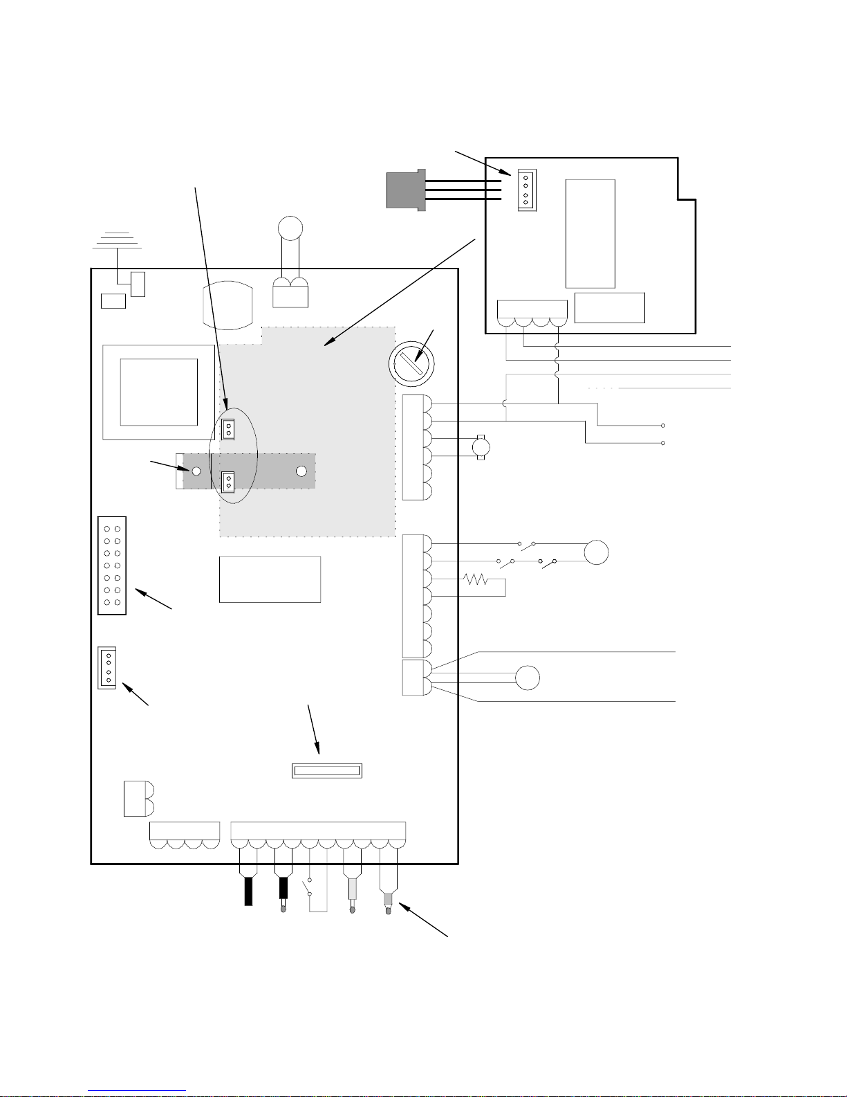
43
13.5 BI-FIRE MID – BI-FIRE wiring diagram (Motherboard I023)
TRANSFORMER
IGNITION RELAY
EARTH
FLUE GAS
EXTRATION
INTAKE DEVICE
PHASE
NEUTRAL
230Vac
NETWORK
BROWN
BLUE
RECIRCULA TION
PUMP
M
SCREW FEED
MOTOR REDUCER
ALF ALP
IGNITION
RESISTANCE
ROOM
THERMOSTA
T
CN4
CN8
CN9
CN13
CN5
CN1
CN2
CN3
CN7
PELLET SIDE
FUMES PROBE
FUSE
3,15A 5X2 0
N.PEL. N.H20
N.AMB.
TERM.
BLUE
RED
WATER
PROBE
-TC1+
ACC. COC.
N
F
SCAM.
FUMI
N
AL1AL2
IMPORTANT: DO NO T
INVERT THE PO SITION
OF THE W IRES
CN6
CN6
RELAY
EXPANSION BOAR D I055
FOR 3-WAY VALVE (OPTIONAL)
DISSIPATER
N
F
SCAM
FUMI
CN15
FUSE
4A 5X20
connector to CN13
on board I023
New serial connection
EXPANSION BOARD I055 CONNECTED TO I023
WITH CONNECTORS CN10 AND CN12
CN12
CN10
FASTENING
SCREWS
BROWN ON CABLE
BLACK ON CABLE
BLUE ON CABLE
GREEN/YELLOW EARTH ON CAB LE
BOARD I023
CN14
DISPLAY
CONNECTOR
WIRES ( WITH 220V)
CONTROL OF ANT
COUPLED
BOILER
4 x 0,75 CABLE (OPTIONAL)
FOR CONNECTION OF THE
MOTORISED 3-WAY VALVE
SCAM.
AUX
ALT
WOOD SIDE
FUMES PROBE
P
HEATING SYSTEM
PUMP
P
LEVELLING
DEVICE
SAFETY DEVICES KEY:
ALP = DOOR CLOSING MICRO SWITCH
ALF = FLUE GAS PRESSURE SWITCH
ALT = MANUAL RE-ARM THERMOSTAT
CONNECTOR
FOR SERIAL OR
EXPANSION BOARD
I055 CONNECTION
CONNECT A RELAY AT SET-UP WIRES OUTLET
(POWERED WITH 220V VOLTAGE) FOR ELECTRIC
CONNECTION TO COUPLED BOILER.
CR2032 3Volts
CHRONO-THERMOSTAT
CLOCK BATTERY
THREE-WAY CONNECTION KEY:
BLUE = COMMON
BLACK = PHASE OPENING
BROWN = PHASE CLOSING
YELLOW/GREEN = EARTH MASS
Page 44
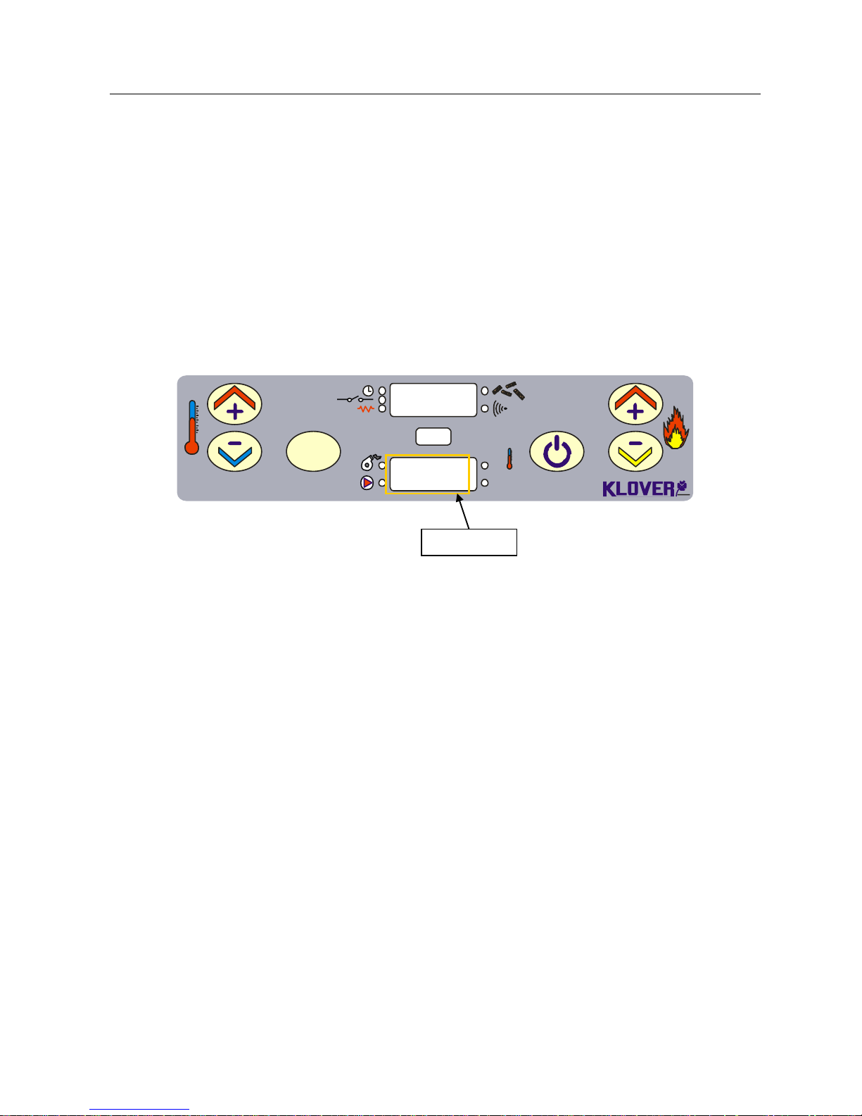
44
14. USEFUL ADVICE
Anticipate change to work phase without having to wait entire ignition cycle.
Keep key 5 pressed (power increase) to go directly to work phase without waiting for stove to perform the
entire ignition cycle. The flue gas must have reached minimum temperature to consider stove on (Pr13), to go
onto work phase. If not, stove repeats ignition cycle.
Do not perform following procedure during "Commissioning".
Anticipate a new stove ignition without having to wait stand-by time during switch-off phase.
Keep key 6 pressed (power decrease) to go directly to a new ignition without waiting for stove to perform the
entire ignition cycle.
The flue gas intake device is in this way switched off. Proceed with new stove ignition.
The stove goes to “At:te” state (wording appearing in lower display meaning “STAND-BY”) if the following
procedure is incorrectly performed in case of new ignition (see figure 13).
SET
OK
Set
°C
1
2 3 4 6
5
At : tE
Off
Display wood/pellet and water flue gas temperature.
The flue gas temperature on pellet and water side can be displayed during ignition or work phase by holding
key 1 down (temperature increase).
The flue gas temperature is displayed on upper display and water in stove temperature on lower display.
The flue gas temperature on wood side can be displayed during ignition or work phase by holding key 2 down
(temperature decrease).
Fig. 13
DIALOGUE
Page 45

45
15. NOTES
________________________________________________________________________________
________________________________________________________________________________
________________________________________________________________________________
________________________________________________________________________________
________________________________________________________________________________
________________________________________________________________________________
________________________________________________________________________________
________________________________________________________________________________
________________________________________________________________________________
________________________________________________________________________________
________________________________________________________________________________
________________________________________________________________________________
________________________________________________________________________________
________________________________________________________________________________
________________________________________________________________________________
________________________________________________________________________________
________________________________________________________________________________
________________________________________________________________________________
________________________________________________________________________________
________________________________________________________________________________
________________________________________________________________________________
________________________________________________________________________________
________________________________________________________________________________
________________________________________________________________________________
Page 46

46
________________________________________________________________________________
________________________________________________________________________________
________________________________________________________________________________
________________________________________________________________________________
________________________________________________________________________________
________________________________________________________________________________
________________________________________________________________________________
________________________________________________________________________________
________________________________________________________________________________
________________________________________________________________________________
________________________________________________________________________________
________________________________________________________________________________
________________________________________________________________________________
________________________________________________________________________________
________________________________________________________________________________
________________________________________________________________________________
________________________________________________________________________________
________________________________________________________________________________
________________________________________________________________________________
________________________________________________________________________________
________________________________________________________________________________
________________________________________________________________________________
________________________________________________________________________________
________________________________________________________________________________
________________________________________________________________________________
Page 47

47
Page 48

48
Via A. Volta, 8
37047 San Bonifacio (VR)
Tel: 045 6101859
Fax: 045 6101858
e-mail: [email protected]
internet: www.klover.it
 Loading...