

KLOCK WERKS Kicker PXA 200.2, Kicker PSC652 Installation Manual
KICKER AMP & SPEAKER
INSTALLATION GUIDE
FOR USE WITH HARLEY DAVIDSON 2014+ FLHT
INCLUDED IN THIS FIT KIT:
> Step-by-step Installation Guide
> 6 1/2” Kicker Speakers Pair
> Kicker Amp 200W
> Stainless Steel Mounting Bracket
> Custom Wiring Harness
> All Necessary Hardware
- 8 - 32 x 1/2” Button Head Bolts
- 8 - 32 Nylock Nuts
- Black Heat Shrink
- Black Cable Tie
- Mounting Hardware
4405-FLHT1401R1 ©2016 KLOCK WERKS
KLOCK WERKS | FLHT KICKER AMP AND SPEAKER INSTALLATION
IMPORTANT INSTALLATION NOTE:
Over-tightening mounting fasteners may result in damage to your motorcycle. Please refer to your service manual for proper procedures and
torque specifications. We cannot be responsible for damage resulting from improper installation techniques. This kit may not be compatible with
some aftermarket head units.
GETTING STARTED
1. Remove the seat and disconnect the battery
2. Remove the passing lamps/turn signals
a. Loosen and remove both fasteners and unplug each passing lamp/turn signal
3. Remove the windshield
4. Remove the outer fairing
a. Remove the four mounting screws, unplug the headlamp and set aside on a soft cloth
5. Remove the fuel tank
a. Remove the console
b. Unplug the fuel fitting on the left side
c. Remove all four mounting bolts and carefully lift the tank off the bike and set aside
6. Remove wire caddy cover
a. Carefully release each tab along the caddy until it lifts completely
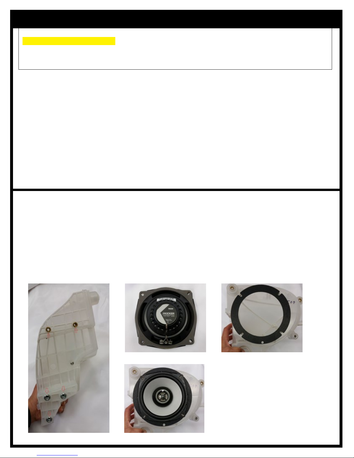
SPEAKER INSTALLATION
1. Remove one of the white speaker pods from the inner fairing
a. There are five fasteners in the center portion and three on the outside to release it from the inner fairing (1)
2. Remove the stock speaker and replace with the PSC652 speaker from the kit
a. Install provided foam gasket material to the back side of each speaker (2)
b. Install the provided speaker ring adapter onto the speaker pod (3)
c. Install the speaker into the pod and fasten with the original speaker screws (4)
3. Reinstall the pod to the inner fairing
4. Repeat for the other side
Note: There may be some connectors that will need to be relocated off of the radio chassis for the amp bracket to fit
21 3
4
 Loading...