

KLOCK WERKS FINC14 Installation Manual
KICKER AMP & SPEAKER
INSTALLATION GUIDE
FOR USE WITH INDIAN CHIEFTAIN
INCLUDED IN THIS FIT KIT:
> Step-by-step Installation Guide
> 5 1/4” Kicker Speakers Pair
> Kicker Amp 100W/50W
> Stainless Steel Mounting Brackets
> Custom Wiring Harness
> Black Heat Shrink
> Black Cable Tie
> All Necessary Hardware
- 8 - 32 x 1/2” Button Head Bolts
- 8 - 32 Nylock Nuts
- 1/4” - 20 x 5/8” socket head bolts
- 1/4” flat washers
- 1/4” - 20 Klip Nuts
- M6 x 1.9 x 15mm Sockethead bolts
- M10 x 1.5 x 55mm flanged head bolt
- M10 x 1.5 flanged lock nut
- 1/8” x 5.25” speaker spacer rings
KLOCK WERKS | INDIAN CHIEFTAIN KICKER INSTALLATION 2
GETTING STARTED | *Please refer to model appropriate service manual for procedures and torque specifications
1. Protect painted surfaces with a soft cloth.
2. Remove the seat.
3. Remove fastener for the ECU tray and safely keep ECU assembly away from the battery box during
installation of this kit. DO NOT disconnect the ECU.
4. Disconnect battery.
HARNESS INSTALLATION
5. Follow the proper procedure to remove the fuel tank.
6. Follow the proper procedure to remove the outer fairing.
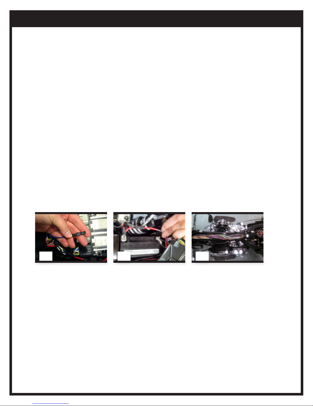
7. Use the supplied heat shrink to seal the male spade connector on the blue wire that accompanies the
power leads. (Pic 1)
8. Remove the fuse on the positive lead of the supplied audio harness.
9. Attach the negative and positive lead and battery cables to the battery, ensuring the leads follow the angle
of the battery cables. (Pic 2)
10. Reinstall the ECU assembly.
11. Remove the plastic wire caddy cover underneath the fuel tank. (Pic 3)
12. Route the speaker wires into the caddy, along the right side of the frame neck and under the fairing.
(speaker wires will be finally routed later)
1 2 3
AMP INSTALLATION
13. Remove tip-over switch from its original mounting point, under the seat, and save hardware
for reuse. (Pic 4)
14. Fasten tip-over switch onto supplied mounting bracket with hardware saved from step 13.
15. Remove the M10 bolt on the left side of the chassis, under the side cover, and replace with the
longer supplied M10 bolt. (Pic 5)
16. Slip the tip-over switch bracket onto the bolt and secure with the supplied M10 nut, ensuring that
the switch is in the up position. (Pic 6)
17. Install the two supplied clip nuts onto the lower amplifier bracket. (Pic 7)
18. Install the lower amplifier bracket to the motorcycle using the two supplied 6mm socket head
fasteners. (Pic 7)
19. Install the amplifier to the main amplifier bracket using the supplied hardware, ensuring the harness
connector is to the left side. (Pic 8)
 Loading...