

Klockner Moeller PS 416-TCS-200 Hardware And Engineering

Hardware and Engineering
PS 416-TCS-200
Telecontrol Card
08/97 AWB 27-1298 GB
1st published 1997, edition 08/97
© Klöckner-Moeller GmbH, Bonn
Author: Thomas Dahmen
Editors: Klaus Krüger, Thomas Kracht
Translators: Christopher Baker, Terence Osborn

Caution!
Dangerous electrical voltage!
Before commencing the installation
● Disconnect the power supply of the
device.
● Ensure that the device cannot be
accidentally restarted.
● Verify isolation from the supply.
● Earth and short circuit.
● Cover or enclose neighbouring units that
are live.
● Follow the engineering instructions
(AWA) of the device concerned.
● Only suitably qualified personnel may
work on this device/system.
● Before installation and before touching
the device ensure that you are free of
electrostatic charge.
● Connecting cables and signal lines
should be installed so that inductive or
capacitive interference do not impair the
automation functions.
● Install automation devices and related
operating elements in such a way that
they are well protected against
unintentional operation.
● Suitable safety hardware and software
measures should be implemented for
the I/O interface so that a line or wire
breakage on the signal side does not
result in undefined states in the
automation devices.
● Ensure a reliable electrical isolation of
the low voltage for the 24 volt supply.
Only use power supply units complying
with IEC 60 364-4-41 or HD 384.4.41 S2.
● Deviations of the mains voltage from the
rated value must not exceed the
tolerance limits given in the
specifications, otherwise this may cause
malfunction and dangerous operation.
● Emergency stop devices complying with
IEC/EN 60 204-1 must be effective in all
operating modes of the automation
devices. Unlatching the emergency-stop
devices must not cause uncontrolled
operation or restart.
● Devices that are designed for mounting
in housings or control cabinets must only
be operated and controlled after they
have been installed with the housing
closed. Desktop or portable units must
only be operated and controlled in
enclosed housings.
● Measures should be taken to ensure the
proper restart of programs interrupted
after a voltage dip or failure. This should
not cause dangerous operating states
even for a short time. If necessary,
emergency-stop devices should be
implemented.
IBM is a registered trademark of International
Business Machines Corporation.
All other brand and product names are
trademarks or registered trademarks of the
owner concerned.
All rights reserved, including those of the
translation.
No part of this manual may be reproduced in
any form (printed, photocopy, microfilm or
any otherprocess) or processed, duplicated
or distributed by means of electronic
systems without written permission of
Klöckner-Moeller GmbH, Bonn.
Subject to alterations without notice.

Contents
About This Manual 3
Other manuals (AWBs) 3
1 Setting Up A Telecontrol Station With
The PS 416 Controller 5
Procedure 8
2 About The Card 9
Task of the PS 416-TCS-200 9
Hardware and software requirements 9
Construction of the PS 416-TCS-200 10
Communication layers model 11
3 Engineering 13
Number of PS 416-TCS-200 cards in
the rack 13
Power supply 13
Terminal assignments 13
Selection of modem 15
Electromagnetic compatibility 15
4 Configuration 19
08/97 AWB 27-1298-GB
5 Installation 23
Installing the PS 416-TCS-200 in the rack 23
6 Operation 25
Function of the PS 416-TCS-200 card 25
Startup behaviour 26
Shutdown behaviour 27
7Diagnostics 29
Appendix 31
Technical data 31
Glossary 32
Index 35
1

2
08/97 AWB 27-1298-GB

About This Manual
This card has been developed for remote metering,
remote indication and remote control and supports
the data security protocols FT 1.2 and FT 3
(asynchronous) as per the IEC 870-5 standard for
telecontrol equipment and systems.
This manual describes the structure, planning,
configuration, installation, operation and also the
testing and diagnostics of the PS 416-TCS-200
communication processor. The PS 416-TCS-200 is a
communication processor for PS 416 programmable
logic controller. With the aid of the PS 416-TCS-200
communication processor the PS 416 can be
connected as telecontrol station to a telecontrol
network.
This documentation is intended for the project
planner, programmer and commissioning engineer.
This documentation will enable such users to
connect the PS 416 to a telecontrol system.
A general knowledge of control and communication
engineering is required for a good comprehension of
this technical documentation.
Other manuals (AWBs) The fundamentals of remote control using compact
PLCs are described in a separate manual. Each of
the individual components also has its own manual.
Guide to telecontrol, AWB 27-1299-GB
ZB 4-501-TC1:
Hardware and engineering, telecontrol card
ZB 4-501-TC1, AWB 27-1297-GB
08/97 AWB 27-1298-GB
3

About This Manual
PS 416-TCS-200:
Hardware and engineering, telecontrol card PS 416TCS-200, AWB 27-1298-GB
Leased line S 40-AM-TL:
Telecontrol via leased line, application module S 40AM-TL, AWB 27-1301-GB
Dial-up line S 40-AM-TD:
Telecontrol via dial-up line, application module
S 40-AM-TD, AWB 27-1300-GB
4
08/97 AWB 27-1298-GB
1 Setting Up A Telecontrol Station With
The PS 416 Controller
The PS 416-TCS-200 communication processor
forms part of the PS 416 modular control system.
With the PS 416-TCS-200 the individual controller
can be integrated into a telecontrol system. Here the
controller can be the central station or a substation.
Communication with the telecontrol network is
effected via modem and modem cable.
Communication is supported by task-specific
application modules (function blocks).
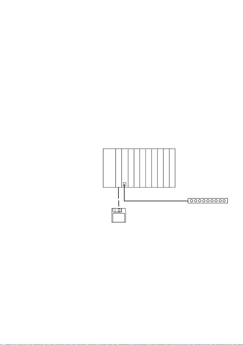
a
CPU PS 416
PS 416-TCS-200
08/97 AWB 27-1298-GB
ZB 4-254-KB1
S 40-AM-TD/TL
Figure 1: Layout of a telecontrol station with the PS 416
programmable controller
a Central station
b Modem
b
Either a dial-up line or a leased line can be used as the
transmission medium.
In the case of the dial-up line existing telephone
networks are used as transmission medium. All of the
modems in the central station and substations must
be modems with dialling capability. At the request of
5
Setting Up A Telecontrol
Station With The PS 416
Controller
the central station or the substation the modems set
up a connection with a specified telephone number.
In the case of the dial-up line both the central and also
the substation can take over the function of a primary
station or the function of a secondary station:
Primary station:
Station which initiates data transport
Secondary station:
Station which replies to a data request
Communication of one station with several stations
simultaneously is not possible.
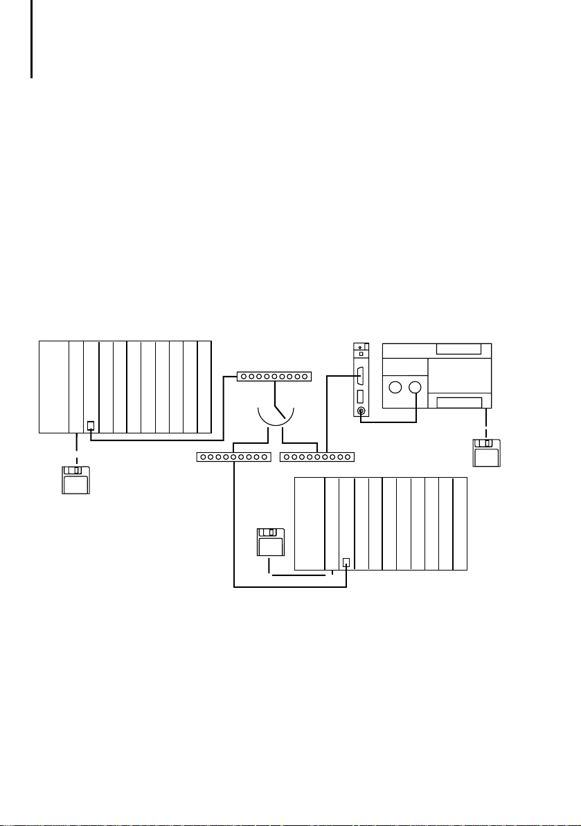
a
S 40-AM-TD
CPU PS 416
PS 416-TCS-200
ZB 4-254-KB1
ZB 4-501-TC1
b
c
b
S 40-AM-TD
b
S 40-AM-TD
PS 416-CPU-400
Figure 2: Telecontrol system with PS 416 components and
dial-up line configuration
a Central station – primary station / secondary station
b Dial-up modem
c Dial-up line
d Substation – primary station / secondary station
d
PS 416-TCS-200
d
PS 4-200
6
08/97 AWB 27-1298-GB
Other manuals (AWBs)
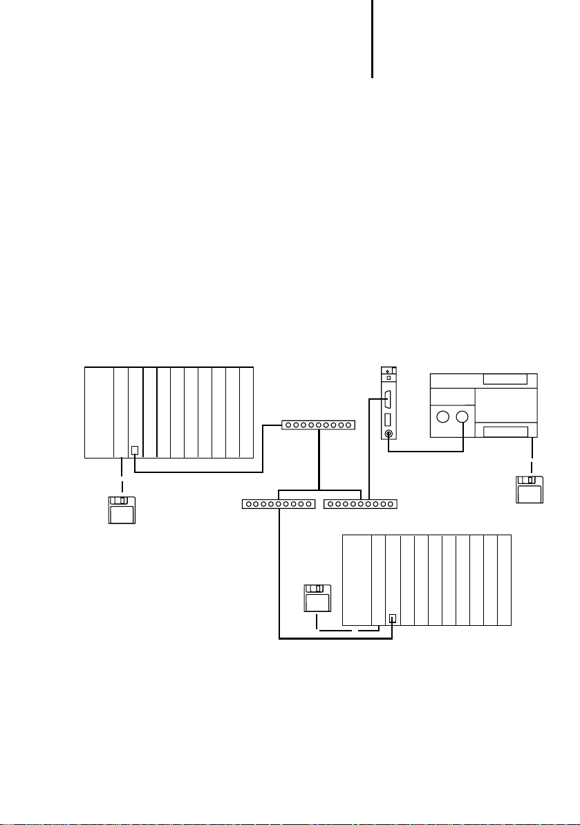
In the case of the leased line all substations are
permanently connected to the central station.
If more than one secondary station is addressed via
the leased line only point-to-point leased modems
(party line) may be used. The central station will in
this case always be a primary station and the
substations always secondary stations. This makes it
possible for the central station to send messages to
all substations simultaneously.
Only the central station can initiate communication.
A substation cannot autonomously initiate
communication with the central station or with
another substation.
a
CPU PS 416
S 40-AM-TL
PS 416-TCS-200
ZB 4-254-KB1
ZB 4-501-TC1
b
b
S 40-AM-TL
Figure 3: Telecontrol system with PS 416 components and
leased line configuration
a Central station – primary station
b Modem (party line)
c Substation – secondary station
b
c
CPU PS 416
c
PS 4-200
S 40-AM-TL
PS 416-TCS-200
08/97 AWB 27-1298-GB
7

Setting Up A Telecontrol
Station With The PS 416
Controller
Procedure The following procedure is recommended for
connecting the PS 416 to a telecontrol system.
E Define all requirements made on the telecontrol
system – for example, data security, number of
stations, and so on. A detailed description will be
found in the “Guide to telecontrol” manual.
E Select the application module which matches
your requirements. Relevant factors here include:
station type (modular – compact), station class
(primary – secondary), number of stations.
E Configure the interface parameters for the
PS 416-TCS-200 in the application module. See
Chapter 4, Configuration.
E Adjust the transmission parameters where
necessary to match the requirements of the data
integrity class. See the “Guide to telecontrol”
manual.
E Install the card in the rack. See Chapter 5,
Installation
E Connect the PS 416-TCS-200 to the modem via
the ZB 4-254-KB1 modem cable. See Chapter 5,
Installation
The card is now installed, programmed, configured
and is ready for operation.
8
08/97 AWB 27-1298-GB

2 About The Card
Task of the
PS 416-TCS-200
Hardware and software requirements
The PS 416-TCS-200 communication processor is
used for connecting the PS 416 programmable
controller via a modem to a telecontrol system. It
communicates with other telecontrol stations via a
point-to-point modem or dial-up modem.
The card has its own microcontroller. This means that
it handles the communication process autonomously
without taking up any of the capacity of the PS 416
central processing unit.
Table 1 provides an overview of the hardware and
software requirements for running the
PS 416-TCS-200 within the PS 416 PLC system.
Table 1: Hardware and software requirements
Software
Programming software
Operating system
Application modules
Hardware
Central processing unit
Power supply card:
Subrack
Modem cable
Sucosoft S 40 Manager, Version 2.0 and
higher for PS 416-CPU-400 Version 1.13 and
higher
S 40-AM-TD Version 1.0 (dial-up line)
S 40-AM-TL Version 1.0 (leased line)
PS 416-CPU-400
PS 416-POW-400
PS 416-POW-410
PS 416-POW-420
PS 416-BGT-400/410/420 or 421 with
PS 416-ZBX-401/402/403 potential
equalisation rail
ZB 4-254-KB1
08/97 AWB 27-1298-GB
9

About The Card
Construction of the
PS 416-TCS-200
e
d
r
x
d
c
/
tx
d
e
rro
r
b
f
a
T
CS
-
2
00
Figure 4: Elements of the PS 416-TCS-200
a Switches S1 / S2
b RS 232 – modem port
c LED (error)
d LED (RxD / TxD)
e Interface module
f System EPROM
10
08/97 AWB 27-1298-GB
 Loading...