

Page 1
SOLAR HEATING SYSTEMS
FORCED
CIRCULATION
Vacuumm collectors
SKY 8 CPC 58
SKY 12 CPC 58
SKY 18 CPC 58
SKY 21 CPC 58
Reg. no. 011-7S124R
Page 2

Page 3

1
INDEX
• Introduction . . . . . . . . . . . . . . . . . . . . . . . . . . . . . . . . . . . . . . . . . . . . . . . . . . . . . . . . . . . Pag. 2
• Solar collectors technical data . . . . . . . . . . . . . . . . . . . . . . . . . . . . . . . . . . . . . . . . . . . . . Pag. 5
• Dimensioning . . . . . . . . . . . . . . . . . . . . . . . . . . . . . . . . . . . . . . . . . . . . . . . . . . . . . . . . . . Pag. 6
• Checks and parameters indispensable for dimensioning . . . . . . . . . . . . . . . . . . . . . . . . . Pag. 7
• Connection example of collectors in series . . . . . . . . . . . . . . . . . . . . . . . . . . . . . . . . . . . Pag. 8
• Connection example of collectors in parallel . . . . . . . . . . . . . . . . . . . . . . . . . . . . . . . . . . Pag. 9
• Preliminary warnings and checks . . . . . . . . . . . . . . . . . . . . . . . . . . . . . . . . . . . . . . . . . . . Pag. 11
• Practical table for the choice of piping . . . . . . . . . . . . . . . . . . . . . . . . . . . . . . . . . . . . . . . Pag. 13
• Clearance . . . . . . . . . . . . . . . . . . . . . . . . . . . . . . . . . . . . . . . . . . . . . . . . . . . . . . . . . . . . . Pag. 15
• Flat roof kit assembly layout . . . . . . . . . . . . . . . . . . . . . . . . . . . . . . . . . . . . . . . . . . . . . . . Pag. 16
• Sloped roof kit assembly layout . . . . . . . . . . . . . . . . . . . . . . . . . . . . . . . . . . . . . . . . . . . . Pag. 22
• Hydraulic connections . . . . . . . . . . . . . . . . . . . . . . . . . . . . . . . . . . . . . . . . . . . . . . . . . . . Pag. 27
• Instructions for the assembly of the F1/PT 1000 probe . . . . . . . . . . . . . . . . . . . . . . . . . . . Pag. 28
• Loading the system through the solar station . . . . . . . . . . . . . . . . . . . . . . . . . . . . . . . . . . Pag. 29
• Inclinations of the solar collectors . . . . . . . . . . . . . . . . . . . . . . . . . . . . . . . . . . . . . . . . . . Pag. 30
• Orientation of the collectors . . . . . . . . . . . . . . . . . . . . . . . . . . . . . . . . . . . . . . . . . . . . . . Pag. 31
• Maintenance and repairs . . . . . . . . . . . . . . . . . . . . . . . . . . . . . . . . . . . . . . . . . . . . . . . . . Pag. 32
• Safety systems . . . . . . . . . . . . . . . . . . . . . . . . . . . . . . . . . . . . . . . . . . . . . . . . . . . . . . . . . Pag. 33
• Indications regarding transport and handling . . . . . . . . . . . . . . . . . . . . . . . . . . . . . . . . . . Pag. 34
• For the user . . . . . . . . . . . . . . . . . . . . . . . . . . . . . . . . . . . . . . . . . . . . . . . . . . . . . . . . . . . Pag. 35
• Grand Soleil Medium Kit . . . . . . . . . . . . . . . . . . . . . . . . . . . . . . . . . . . . . . . . . . . . . . . . . Pag. 36
• Grand Soleil Kit . . . . . . . . . . . . . . . . . . . . . . . . . . . . . . . . . . . . . . . . . . . . . . . . . . . . . . . Pag. 37
• Grand Soleil Plus Kit . . . . . . . . . . . . . . . . . . . . . . . . . . . . . . . . . . . . . . . . . . . . . . . . . . . . Pag. 38
• Totalenergy Kit . . . . . . . . . . . . . . . . . . . . . . . . . . . . . . . . . . . . . . . . . . . . . . . . . . . . . . . . Pag. 39
• Totalenergy Plus Kit . . . . . . . . . . . . . . . . . . . . . . . . . . . . . . . . . . . . . . . . . . . . . . . . . . . . . Pag. 40
• Data detection card for solar heating systems . . . . . . . . . . . . . . . . . . . . . . . . . . . . . . . . . Pag. 41
• Certifications . . . . . . . . . . . . . . . . . . . . . . . . . . . . . . . . . . . . . . . . . . . . . . . . . . . . . . . . . . Pag. 42
Page 4
2
MAKING USE OF SOLAR ENERGY
Solar energy is among the most abundant and available free renewable energies on the earth’s surface. To have an idea of
the energy that the sun radiates onto the earth, according to the latitude, the average daily solar radiation in Italy varies
from 4 to 5.5 kWh on a surface of 1 square metre.
The use of a solar heat collector with vacuum technology is accredited, as shown by the experts in the solar sector and
by laboratory tests carried out according to EN European Standards, to be the most technically efficient system for capturing the energy released by the sun through the entire year.
Considering the daily heat energy request per person for domestic hot water use, the use of solar collectors with vacuum
technology with CPC reflector, combined with a standard state-of-the-art designed system, allows energy saving regarding
domestic hot water of up to 80%. While, considering the global load of heat energy requested for domestic hot water and
heating, the total saving can exceed 40%.
This considerable energy saving constitutes an important contribution to the reduction of the emissions of noxious
substances, deriving from combustion, into the atmosphere and particularly to the reduction of CO2, the main reason for
environmental heating due to the greenhouse effect.
The functioning principle of a solar heating system can be described simply.
The solar vacuum collector with CPC reflector captures solar radiation and heats up. The heat gathered is transferred by
heat exchage to a water tank, which acts as a storage tank. The amount of solar energy that the collector can transfer to
the tank depends on its capacity to absorb solar radiation and on the level of insulation, which reduces the loss of energy
captured by the collector.
The creation of the vacuum by removing the air from the gap in the glass tube achieves a layer of the best heat insulating
material existing in nature. The principle has been known about for a century and is appreciated in the form of the
thermos.
Using this arrangement, the collectors optimise the use of solar energy also during the change of seasons and during the
winter.
ADVANTAGES OF CPC DIFFUSION VACUUM TECHNOLOGY
- High temperatures and yields even in unfavourable atmospheric conditions, e.g. with low external temperatures.
- High absorption even with diagonal light thanks to the circular shape of the absorbing device.
- Top quality and high efficiency solar vacuum tube, of our own production and with high level of forced vacuum.
- Duration through time: no delicate glass-metal couplings that degenerate the level of vacuum in the glass pipe through
time.
- Duration through time: high resistance and duration of the selective capturing layer also thanks to the protection of the
vacuum.
- Loss of load contained thanks to the circulation of the flow in parallel in the circuit with "U"-shaped pipes.
- Maximum yield with less requirement for surfaces (half of the absorbant surfaces are normally necessary with respect
to a traditional absorbing panel).
- Treated spacial aluminium concentrator reflector, with double CPC paraboloidal section (Compound Parabolic
Concentrator) with optimised optics for the solar collector, to convey the sun’s non-incident rays onto the vacuum tube.
- High efficiency all year round.
- Low assembly costs: collector already assembled and easy to fix.
- Easy and immediate tube replacement with the EASY CHANGE system.
- Excellent heat insulation performance of the heat-carrying circuit also at low temperatures.
- Modern and elegant design.
Introduction
Page 5

3
Vacuum area
Multy-layer metal “CERMET” layer
Vacuum tube with double wall
Aluminium absorbing device
Copper pipe
THE VACUUM TUBE
AN OLD PRINCIPLE APPLIED TO AN INNOVATIVE TECHNOLOGY
The creation of the vacuum by removing the air from the gap in the glass tube achieves the best heat insulating material
possible. The principle has been known about for a century and is appreciated in the form of the thermos.
Using this arrangement, the collectors optimise the use of solar energy also during the change of seasons and during the
winter.
The internal surface of the vacuum gap is made selective to the absorption of the solar radiation by means of the laying,
by sputtering, of multiple metal layers with a micro-metric thickness, which is called CERMET and which cover the
absorption of the entire spectrum of electro-magnetic radiation of the sun.
The selective layer is designed especially to resist the high temperatures that are generated, through time. The presence
of the vacuum ensures the protection against infiltrations of humidity and atmospheric agents, thus guaranteeing unlimited duration and the maintenance of the capturing perfomance.
TRANSMISSION OF HEAT TO THE HEAT-CARRYING FLUID
The exchange of the heat collected takes place by a relevant absorbing device in aluminium, which on contact with a “U”
-shaped copper pipe transfers the heat to a heat-carrying fluid present in the solar collector circuit.
Page 6
4
WHY CHOOSE KLOBEN
The research carried out to increase the yield of the Kloben solar collectors have allowed to discover efficient and
innovative solutions to make the best of the sun and its diffused light. For this reason particular direct and diffused light
capturers, with CPC, Compound Parabolic Concentrator, geometry have been studied and realised using materials able to
supply optimal yields in total reflection (> 90%) and in reflection with diffused light.
The combination of vacuum tube technology and CPC reflectors applied to the solar collectors, guarantee the best yields,
most of all in situations of little radiation and low external temperatures. The advantage of the Kloben system therefore
has an immediate effect also at an economical level.
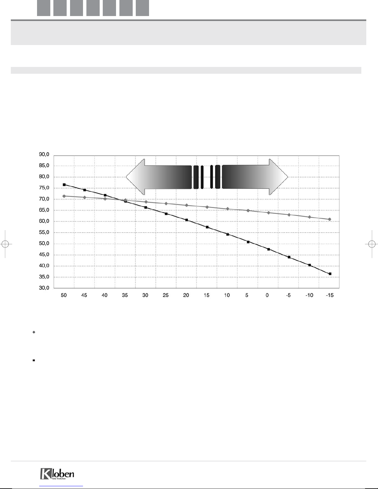
Efficiency curve with radiation at 800 W and average temperature inside heat-carrying fluid of 50°C of the Kloben SKY
CPC 58 DIFFISION model (Test Report no. 07COL623/1 (according to EN 12975-2:2006), ITW Institute, Stuttgart - Solar
Keymark certification).
Efficiency curve with radiation at 800 W and average temperature inside heat-carrying fluid of 50°C of a Solar Keymark
certified flat solar panel (data from Solar Keymark Database - Estif site, (European Solar Thermal Industry Federation))
From the comparison it was seen that for an average T of heat-carrying fluid of 50°C, the Kloben SKY CPC 58 Diffusion
vacuum collector has greater efficiency that the flat collector, up to 35°C of environment T. The difference in efficiency
increases even more on the decrease of the external temperature.
Yiled µ%
Environment temperature [°C]
Summer Winter
Page 7
5
Solar collectors technical data
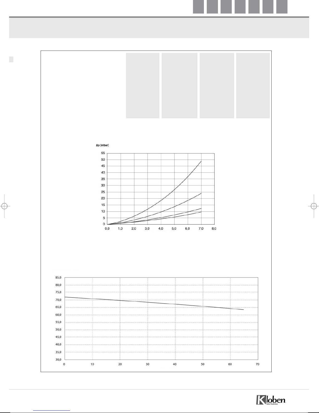
MODEL SKY 8 CPC 58 SKY 12 CPC 58 SKY 18 CPC 58 SKY 21 CPC 58
AMOUNT OF VACUUM TUBES (pc): 8 12 18 21
GROSS SURFACES (m
2
): 1.48 2.16 3.22 3.75
NET SURFACES (m
2
): 1.27 1.89 2.84 3.31
EMPTY WEIGHT (kg): 29 43 65 76
DIMENSIONS (mm)
Height: 1603 1603 1603 1603
Width: 920 1358 2018 2348
Thickness: 140 140 140 140
FEATURES
Circuit of the solar collector with “U”-shaped copper pipes with circulation in parallel
Maximum working pressure: 6.0 bar
Load loss:
Optimal flow rate: 1 l/min per m
2
Maximum working inclination: 90°
Minimum working inclination: 0°
Attachments: to tighten using soinner DN 18 mm
*Test Report no. 07COL623/1 (according to EN 12975-2:2006), ITW, Universität Stuttgart - SOLAR KEYMARK, Reg. no. 011-7S124R
SKY 8
SKY 12
SKY 18
SKY 21
Yield (square interpoling)*:
η0= 0.718%
a1= 0.974 [W·m-2·K-1]
a2= 0.005 [W·m-2·K-2]
(Taverage fluid - Tenvironmental) [K]
Volumetric flow rate [l/min]
Yiled µ%
Page 8

6
Dimensioning
Kloben makes use of a complex software that allows quick, precise and customised calculation of the enrgy requirements
requested, the number of panels necessary and the solar integration supplied, in relation to the destination of use of the
solar system, the details of the structure on which it is to be applied and the climatic data referring to the area of
installation.
For the dimensioning of all components, it is recommended to contact Kloben-authorised staff. However, it is possible to
perform approximate dimensioning of the components necessary for small solar systems (systems up to max 10 m
2
of solar
collector surface, optimal exposure of collectors max 20° from South and inclination at 45°, average daily consumption
per person of about 60 litres at 45°C), using the data shown below:
MAXIMUM DIMENSIONING OF SOLAR PANELS
MAXIMUM DIMENSIONING OF SYSTEM COMPONENTS
Expansion vessel: An approximate measurement consists in considering 6 l for every m2of solar surface installed.
For more accurate dimensioning refer to the solar calculation software of the vessel
available in the Kloben Intranet area.
Anti-freeze liquid: add the following parameters (A + B + C + D)
A. 1/2 of the capcity of the expansion vessel installed
B. 10 l for every 40 m of line (20 delivery + 20 return)
C. 1.17 l for every SKY 8 CPC 58
1.74 l for every SKY 12 CPC 58
2.60 l for every SKY 18 CPC 58
3.07 l for every SKY 21 CPC 58
D. about 15 l for storage from 300 to 500 l
about 20 l for storage from 500 to 750 l
about 30 l for storage from 750 to 1000 l
Solar Station: LOW FLOW for the management of systems with flow rate from 2 to 16 l/min
BIG FLOW for the management of systems with flow rate from 10 to 80 l/min
For more accurate dimensioning refer to the solar calculation software available in the Kloben
Intranet area.
Flow rate adjuster: 1 l/min for every m
2
of solar surface installed.
NORTH CENTRAL SOUTH
ITALY ITALY ITALY
Water at 45°C produced
per m
2
of solar surface (litres) 80 90 100
Heatable radiant surface
(laying distance 10 cm) from 10 to 15 m
2
from 12 to 16 m2from 14 to 18 m
2
for every m2of solar
Relation between solar and swimming pool sup.
(for summer use - ca. 35% ca. 30% ca. 25%
water 26°C - night cover use)
Page 9

7
Checks and parameters indispensable for dimensioning
In order to start with a correct design, aimed at the realisation of the solar system that is the most suitable for maximising
the benefits of the final customer, some important preliminary checks must be carried out and indispensable data must be
gathered for correct dimensioning:
PROJECT LOCALITY:
The locality where the system is to be installed supplies precious indications for dimensioning, such as: average monthly
radiation, average monthly external temperature, mains water average monthly temperature, average relative humidity
temperature, average monthly wind speed.
METHOD OF CONSUMPTION AND PERIOD OF USE OF THE SYSTEM:
Consider the daily requirement of the family; an approximate consumption of hot water at 45°C variable from 50 to 70
l/day per person. Identify any simultaneous requests for the use of domestic hot water. Check the period of use of the
system (seasonal or months of use).
TYPE OF SYSTEM USE:
heating domestic hot water: identify the consumption and temperature of the water requested and the capacity
of the existing storage tank. For maximum dimensionimg of the capacity of the storage tank to be envisioned, it
is possible to refer to about the double of the daily consumption envisioned for the family or inhabitants.
heating non-domestic hot water: hotel, gym etc.-indicating that stated previously regarding the methods of
consumption and periods of use. For this type of system, therefore, an ad hoc design by designers or Kloben tech
nical staff is always necessary.
room heating: only radiating - identify surfaces to be heated, space between tubes and type of insulation.
swimming pool: specifies if covered or outdoor, any night cover use, requested temperature, period of use.
FEATURES OF THE INSTALLATION STRUCTURE:
The surfaces that house the field of solar collectors are an important restriction of the design, which must be considered
as the positioning of the solar collector affects the capturing efficiency of the sun’s radiation. The checks to be carried out
are: possibility of assembly on flat or sloped roof, availability of roof pitch with orientation towards the south or
alternatively with orientation towards east or west, inclination of the pitch, presence of obstacles, etc.
From the existing Standard, UNI 9182, the data inherent to flow rates and requirement of domestic hot water according
to the activity in question and the single appliances, are gathered.
The dimensioning indications stated above refer to maximum dimensioning and are relative to homes with the standard
consumtion of an average family. However, for the correct dimensioning of all parts of the system, it is necessary to
consider the preliminary checks indicated along with all of the details of use of the final user to then proceed with the
definition of the energy requested, the modes of distribution (flow rates, temperatures, period of request) and
successively with the correct dimensioning of all system components on the basis of powers and exchange yields of the
various components: solar surface, solar heat exchanges, storage, etc.
For this reason and for accurate dimensioning refer to Kloben specialised technical staff.
N.B. IF THE SOLAR INSTALLATION IS INTRODUCED ONTO SYSTEMS THAT ALREADY
FUNCTION, IT IS INDISPENSABLE TO HAVE THE DETAILED LAYOUT OF THE EXISTING
HEATING STATION, WITHOUT WHICH IT WILL NOT BE POSSIBLE TO SUPPLY ANY
PERFORMANCE GUARANTEE.
Page 10
8
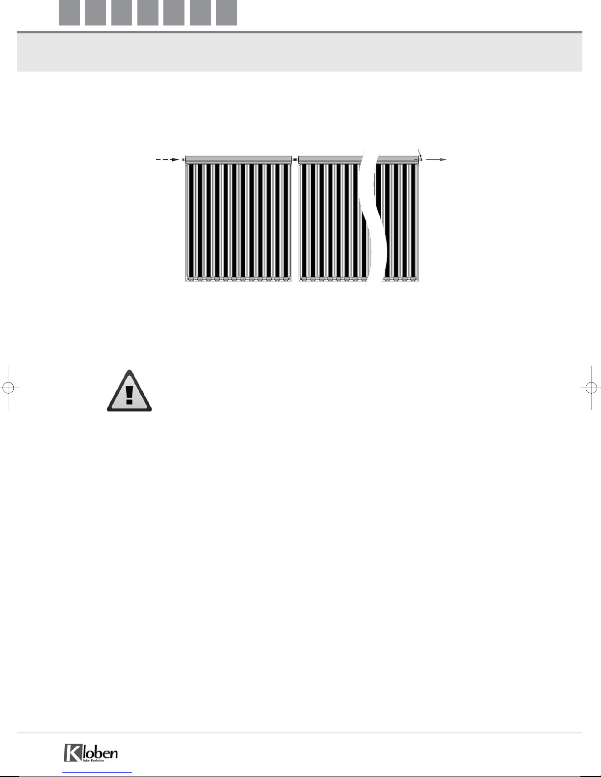
Example of connection of the collectors in series
ATTENTION: do not connect more than n° 4 collectors in series
Probe S1
Page 11

9
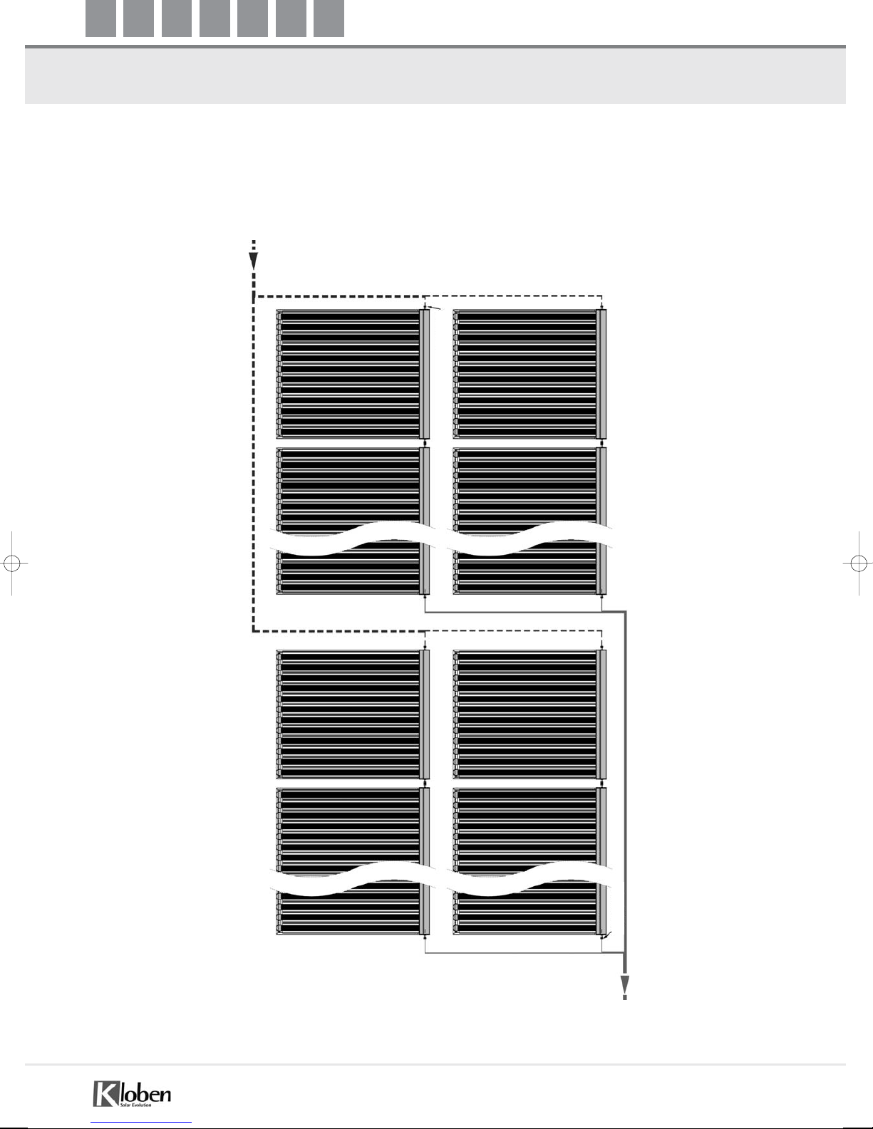
Example of connection of the collectors in parallel
TICHELMAN SYSTEM: consists in the hydraulic balancing of the collector coils.
EXAMPLE 1
EXAMPLE 2
Probe S1
Probe S1
Page 12
10
Example of connection of the collectors in parallel
TICHELMAN SYSTEM
EXAMPLE 3
Probe S1
Probe S1
Page 13
11
Warnings and preliminary checks
The installer is asked to carefully follow the recommendations and indications that are listed successively; as well as
performing all controls requested before system start-up.
ANTI-FREEZE HEAT-CARRYING FLUID:
The heat-carrying fluid used and supplied consists in a special liquid with anti-freeze properties, TYFOCOR LS. This fluid
is specially for use in solar plants with high heat yield like vacuum tube collectors. It is totally pre-mixed and ready for
use. It guarantees protection from freezing to -28°C.
It contains corrosion inhibitors that guarantee efficient protection and duration of the copper pipes, (and all other metals
and alloys used) in particular from corrosion and deposits.
Warnings: In order to maintain the protective features of TYFOCOR LS unaltered, it must not be mixed with other
heat-carrying fluids and anti-freeze or diluted with water. Any top-up owing to the loss of fluid must be compensated
exclusively with TYFOCOR LS. Before loading always check that there is no water in the circuit.
The use of deposited metals is advised for soldering. For welding points the use of deposited metals is recommended for
brazing in silver and copper.
TYFOCOR LS does not attack the sealing materials normally used in solar systems. However, attention must be paid that
all sealing materials are resistant to the maximum temperature of the heat-carrying fluid. Failure to comply with these
checks can lead to the warranty of the solar collector becoming void.
LOADING:
- Before starting the system loading operation, make sure that the solar collectors are at low temperature.
The panels must be covered at least 3 hours before loading.
- The system must be loaded by carefully following the instructions given on page 25 of this manual. The use of the
supplied system loading pump is also recommended (code 101010045).
Correct loading allows the complete elimination of air in the solar circuit and its correct functioning.
- The system’s optimal functioning pressure, to be calibrated in the loading phase is 3/3.5 bar in the heating station and
at least 2/2.5 bar at the panels, with the system at a standstill.
DIMENSIONING:
- Before starting the solar system it is good practice to check that dimensioning and the adjustment of the individual
components ( panels, expansion vessel, glycol, flow rate adjuster, solar station) are in compliance with that indicated on
page 5 of this manual.
- It is indispensable that the diameter of the copper pipes making up the solar circuit are in compliance with that
indicated on page 11 of the following manual. If in doubt, refer to Kloben authorised staff or our technical dept.
INSTALLATION AND RESISTANCE TO LOADING STRESS, WIND AND SNOW:
The installation of solar collectors on flat and sloped roofs envisions indispensable preliminary checks that clarify the
following critical aspects:
- Static stability of the roof for assembly of the collectors
- Accessibility of the roof housing the system and sufficient access and freedom of movement in safety
- Fixing quality of the structure connections and support devices of the solar collectors to the building support (loft
structure, flat roof structure, etc.).
On the basis of the place of installation selected, the locality, the height from the ground, exposure, topography of the
land, the climatic conditions of the areas, etc. preliminary checks must be made of the loading conditions owing to the
wind (average, peaks due to gusts and the presence of storms) and snow on the basis of that envisioned by the
"Departmental Circular dated 4 July 1996, n. 156" regarding implementation "technical standards relative to the general
criteria regarding the safety checks of the constructions and loads and overloads", Legislative Decree dated 16 January
1996.
In the calculations regarding the evaluation of stress of individual and combined loads owing to wind and snowfall, a
maximum sustainable load must be considered, normal to the surface of the collector of 0.90 kN/m2.
The solar collector has been designed to suitably resist combined conditions of wind and snow, the most serious
features of the Italian territory. However, if phenomena of an exceptional nature should occur or situations or loads
exceeding the maximum load of the panel it is good practice to prepare additional protections, such as tie-rods and
Page 14
12
reinforcements for stabilisation.
MATERIALS:
- All pipes making up the solar circuit must be in copper. The use of other materials such as zinc, stainless steel, plastic,
brass and similar is not recommended. If materials different from copper are used, it will be impossible to guarantee
correct functioning of the system.
- All joints must be welded or with tightening connections for copper pipes.
The use of any other materials can jeopardise the sealing of the joints through time.
- To prevent sealing problems of the hydraulic joints of the solar circuit owing to heat stress, always check the distance
at which the field of solar collectors is found with respect to the storage tanks. In all cases it is recommended always
to make the joints with high temperature Teflon.
- The copper pipes must be insulated using a sheath for high temperatures such as the Kloben Solare.
CHECKS:
- Check that, with the system unloaded, the expansion vessel is calibrated at 2 bar.
- Check the correct connection of the probes to the solar control unit.
- Check that the solar control unit is connected correctly to the mains.
- Check that the setting of the solar control unit parameters is in compliance with that prescribed in the design phase.
N.B.: The solar collectors cannot remain exposed to solar radiation for long periods of time without being
loaded (ten days).
Page 15
13
Practical table for the choice of piping
FLOW RATE AND PIPING SECTION
(WITH MAXIMUM LENGTH OF 20 METRES FOR DELIVERY AND 20 METRES FOR RETURN)*
* IF THE CIRCUITS HAVE A LONGER LENGTH OR A CONSIDERABLE NUMBER OF BENDS, PLEASE CONTACT
KLOBEN AUTHORISED STAFF.
For further indications regarding the choice of piping combinations refer tot he Kloben calculation software, present in
the intranet area at: http://solar.kloben.it/impianto
N.B.: As well as the choice of piping, for correct functioning of the solar system correct dimensioning of all components
is necessary (page 5 of this manual).
N.B.: Page 12 of this manual must be consulted for the choice of the solar station.
N.B.: If a greater solar surface is required, more parallel rows will be constituted, each with the same surface area,
connected to each other using the TICHELMAN method (page 8 and 9 of this manual).
N.B.: For systems with particular dimensions and non-standard features, specific calculations must be made to
determine loss of load, pipe diameter, etc.
Cylinder [litres] Type and number collector Flow rate [l/min] Ø Piping [mm]
150 1 x SKY 8 1.27 Copper 14
150 1 x SKY 12 1.89 Copper 16
200 1 x SKY 12 1.89 Copper 16
200 1 x SKY 18 2.84 Copper 16
300 1 x SKY 18 2.84 Copper 16
300 1 x SKY 21 3.31 Copper 16
300 2 x SKY 12 3.78 Copper 18
500 1 x SKY 12 + 1 x SKY 18 4.73 Copper 18
500 2 x SKY 18 5.68 Copper 18
600 2 x SKY 21 6.62 Copper 18
750 3 x SKY 18 8.52 Copper 22
800 3 x SKY 18 8.52 Copper 22
1000 4 x SKY 18 11.36 Copper 22
1500 6 x SKY 18 17.04 Copper 28
2000 8 x SKY 18 22.72 Copper 35
3000 12 x SKY 18 34.08 Copper 35
Page 16

14
LOW - FLOW STATION PUMP FEATURES Flow rate 2-16 l/min
BIG - FLOW STATION PUMP FEATURES Flow rate 10-80 l/min
For more accurate dimensioning, refer to the solar calculation software available in Intranet.
Current I: Onside thermal overload settings.
Measurements - Weight
Motor Data
Single-phase motor (EM) 2 poles - 1
˜
230 V, 50 Hz
Nom. Power
P. max
W
Speed/N. of revs.
n.
1/min.
Absorbed power
P.
W
Current
I
A
Condenser
µF/VDB
Motor
Protection
Measurements - Weight
Motor Data
Single-phase motor (EM) 2 poles - 1
˜
230 V, 50 Hz
Page 17

15
Clearance
Model A B
SKY 8 983 mm 910 mm
SKY 12 1424 mm 1350 mm
SKY 18 2084 mm 2010 mm
SKY 21 2414 mm 2340 mm
Page 18

Flat roof kit assembly layout
16
Position the fixing beams complete with base plate onto the ground,
taking care to respect the maximum distances indicated in the following figure.
Bolt the template support uprights to the fixing beams (see figure below)
ASSEMBLY LAYOUT FOR 1 SKY CPC 58 PANEL: 8 - 12 - 18 - 21
Model A max
SKY 8 300 mm
SKY 12 680 mm
SKY 18 1300 mm
SKY 21 1500 mm
Fixing beam with base plate
Small base plate
Template support uprights
Page 19

17
Flat roof kit assembly layout
Fix the frame to the loft suitably. The nuts and bolts to use must be made in relation to the sub-base material. Each base
plate has 4 holes measuring 12 mm.
Position and fix the support templates according to that indicated in the figure
Solar Panel
support template
Page 20

18
Flat roof kit assembly layout
ASSEMBLY LAYOUT FOR 2 SKY CPC 58 PANELS: 8 - 12 - 18
In the case of installation in series of 2 SKY CPC 58 8, 12, 18 panels, respect the distances indicated in the figure,
where P (support plate width) is a fixed measurement.
ASSEMBLY LAYOUT FOR 3 AND MORE SKY CPC 58 PANELS: 8 - 12 - 18
In the case of installation in series of 3 or more SKY CPC 58 8, 12, 18 panels, rrespect the distances indicated in the
figure where P (support plate width) and C are fixed measurements.
Model P B max
SKY 8 150 mm 535 mm
SKY 12 150 mm 970 mm
SKY 18 150 mm 1500 mm
Model P B max C
SKY 8 150 mm 535 mm 840 mm
SKY 12 150 mm 970 mm 1280 mm
SKY 18 150 mm 1500 mm 1940 mm
Page 21

19
Flat roof kit assembly layout
ASSEMBLY LAYOUT FOR 2 AND MORE SKY CPC 58 PANELS: 21
In the case of installation in series of 2 or more SKY CPC 58 21 panels, 2 support brackets for each collector are
necessary, as described in the figure. Respect the maximum distance A as indicated in the figure where P is the width of
the support plate.
Model P A
SKY 21 150 mm 1500 mm
Page 22

20
TITOLO
Flat roof kit assembly layout
CONNECTIONS AND VENT KIT
CONNECTION NUT DN 18
SPINNER DN 18
REINFORCEMENT INSERT DN 18
KLOBEN SOLAR VENT
CONNECTION DN 18
Page 23

21
Flat roof kit assembly layout
Position the collectors near to each other and bolt them (without tightening) to the support templates in the holes
already prepared (Figure 4), by means of the screws present on the panels (there are 4 screws for each collector).
Then join the panels using the tightening connections supplied and already positioned on the collector (Figure 6). After
this operation tighten the panels onto the templates.
Detail of collector joining by means of
tightening connection
Page 24

22
Sloped roof kit assembly layout
Position the fixing brackets, supplied in the kit, onto the sub-base as shown in the figure.
Each fixing bracket has 4 holes measuring 12 mm. the choice of nuts and bolts must be made keeping in mind the
structure and material of the sub-base.
Fixing bracket
ASSEMBLY LAYOUT FOR 1 SKY CPC 58 PANEL: 8 - 12 - 18 - 21
In the case of installation of 1 SKY CPC 58 8, 12, 18 or 21 panel, respect the distances indicated in the figure, where P
(support plate width) is a fixed measurement and A and Z are variable.
Model P A max Z max Z min
SKY 8 150 mm 280 mm 1500 mm 880 mm
SKY 12 150 mm 680 mm 1500 mm 880 mm
SKY 18 150 mm 1300 mm 1500 mm 880 mm
SKY 21 150 mm 1500 mm 1500 mm 880 mm
Page 25

23
Sloped roof kit assembly layout
ASSEMBLY LAYOUT FOR 2 SKY CPC 58 PANELS: 8 - 12 - 18 IN SERIES
In the case of installation in series of 2 SKY CPC 58 8, 12, 18 panels, respect the distances indicated in the figure,
where P (support plate width) is a fixed measurement and B is variable.
ASSEMBLY LAYOUT FOR 3 AND MORE SKY CPC 58 PANELS: 8 - 12 - 18 IN SERIES
In the case of installation in series of 3 or more SKY CPC 58 8, 12, 18 panels, respect the distances indicated in the
figure where P (support plate width) and C are fixed measurements, while B is variable
Model P B max C
SKY 8 150 mm 530 mm 840 mm
SKY 12 150 mm 970 mm 1280 mm
SKY 18 150 mm 1500 mm 1940 mm
Model P B max
SKY 8 150 mm 530 mm
SKY 12 150 mm 970 mm
SKY 18 150 mm 1500 mm
Page 26

24
ASSEMBLY LAYOUT FOR 2 AND MORE SKY CPC 58 PANELS: 21
In the case of installation in series of 2 or more SKY CPC 58 21 panels, 2 support brackets for each collector are
required as described in figure 2. Respect the maximum distance A as indicated in the figure, where P (support plate
width) is a fixed measurement, while A is variable.
Model P A max
SKY 21 150 mm 1500 mm
Page 27

25
Sloped roof kit assembly layout
Position the collectors near to each other and bolt them (without tightening) to the support templates in the
holes already prepared (Figure 4), by means of the screws present on the panels (there are 4 screws for each
collector).
Then join the panels using the tightening connections supplied and already positioned on the collector
(Figure 12). After this operation tighten the panels onto the templates.
Detail of collector joining by means of
tightening connection
Page 28

26
Sloped roof kit assembly layout
CONNECTION AND VENT KIT
CONNECTION NUT DN 18
SPINNER DN 18
REINFORCEMENT INSERT DN 18
KLOBEN SOLAR VENT
CONNECTION DN 18
Page 29

27
Hydraulic connections
ATTENTION
Once the hydraulic connections have been made, load the solar plant by means of the solar station, scrupulously
following the instructions given on page 25.
It is also fundamental to eliminate all air present in the circuit (to prevent system malfunctioning). Regarding this, the
use of the supplied loading pump is recommended (code art. 101010045).
When loading has been performed another check must be carried out that deaeration has been performed, using the
manual air vent valves mounted on the solar collector.
Position probe F1 ALWAYS ON THE DELIVERY.
For correct introduction of the probe follow the instructions given on page 24
DELIVERY
RETURN
Page 30

28
Instructions for assembly of the F1/PT 1000 probe
For correct introduction of the F1 probe (recognisable by the grey silicone cable) follow the indications given below:
1) Insert the sensitive element of the probe F1 into the relative probe-holder well mounted on the panel, in the direction
indicated in the figure above.
2) Leave the cable to run to the bottom of the well, making sure not to block it completely.
3) Successively, make the electric connections with the solar control unit, carefully following the instructions attached to
the same.
4) Connect the probe electrically to the control unit.
It is advised to wear work gloves and protective goggles in order to prevent injury if the
vacuum tube should accidentally break.
PT 1000/F1probe
(grey silicone cable)
Sensitive element
Probe-holder well
Direction of insertion of F1
Page 31

29
System loading using the solar station
SOLAR STATION: DISPLAY AND DESCRIPTION OF COMPONENTS
LOADING THE SYSTEM
1. Before starting loading, check that the panels have been covered for at least 5 hours.
2. Connect the loading pump delivery pipe to the ball valve (7).
3. Connect the loading pump return pipe to the ball valve (4).
4. Open the ball valves (7 and 4).
5. Close the non-return valve (10) (turning in a clockwise direction).
6. Switch the loading pump on in a way that the anti-freeze circulates in the opposite direction with respect to
normal functioning.
7. If there is a diverter valve on the solar line, check that it is open (manual)
to allow the circulation of anti-freeze in both circuits. At the end of this operation take the valve to its original
position (automatic).
8. Leave the pump to function for the time neecessary to allow the perfect deaeration of the system.
9. Quickly open and close the non-return valve for a few seconds (10). At the end of this operation leave the valve
in the “open” position.
10. Close the ball valve (4).
11. Take the system to a pressure of 3 bar (pressure displayed on the manometer (3)).
12. Close the ball valve (7).
13. Switch the loading pump off.
14. Switch the solar control unit on and check the correct settings and functioning.
15. Set the flow rate adjuster on the value suitable for dimensioning of the system (Page 14 of this manual).
16. Uncover the previously-covered panels.
Safety valve
Flexible pipe connction
for expansion vessel
Manometer
Ball valve
Pump
Flow adjuster
Ball valve
Flow gauge
Non-return valve
Non-return valve
Page 32

30
Inclinations of the solar collectors
On the basis of the way of fixing the rear template support upright of the bracket kit for flat roofs it is possible to obtain
3 different inclinations of the solar collector. The figure shows the 3 different configurations allowed by the brackets.
A larger inclination is used o favour the integration in the winter period. The choice of inclination is made in the design
phase on the basis of user requirements and by evaluating the surplus energy in the summer period.
Consult the Kloben technical dept. for inclinations different to those envisioned.
DISTANCE BETWEEN THE SETS OF COLLECTORS
The figure indicates, for every inclination configuration of the collectors, the minimum distances to be respected between one string of solar collectors in series and another to prevent shadows.
The calculation has been carried out for the inclination of solar rays at the latitude of Rome. For installations in areas
with considerably different latitudes, contact the Kloben technical dept.
INCLINATION 39° INCLINATION 45°INCLINATION 36°
Page 33

31
Orientation of the collectors
It is very important to check that there are no obstructions on the horizon that may jeopardise the radiation of the
collector during transit of the sun.
If obstacles are present they must be signalled as this information conditions the dimensioning of the necessary solar
collectors.
ANY ORIENTATION OF THE PANELS THAT IS DIFFERENT FROM THOSE STATED IN THIS
MANUAL DOES NOT GUARANTEE THE OPTIMAL PERFORMANCE OF THE SYSTEM
Azimuth
The distance of a celestial object from
the north of the horizon of th observer.
It is measured in degrees, starting from
north (that = 0°) in a clockwide
direction.
Zenith
The point of the celestial sphere
directly above the head of the observer.
In the altazimuth system it is the
meeting point of the straigth line,
perpendicular to the ground, passing
through the observer and the celestial
sphere. The opposite point is called
nadir.
Optimal orientation = 0° South
Maximum orientation recommended = 30° South/East -- 30° South/West
Page 34

32
Maintenance and repairs
A yearly inspection is recommended to check the general state of the collector and the solar system in order to
determine the necessity of any repair interventions.
In particular, the following periodic controls must be performed:
Yearly check of system pressure.
If pressure is lower than the optimal working pressure (cf.“WARNINGS AND PRELIMINARY CHECKS”) the causes that
determined the loss must be checked. Only a Kloben authorised after-sales centre can restore optimal working conditions.
Yearly check of anti-freeze protection efficiency.
The anti-freeze heat-carrying liquid must be checked yearly, before the winter. The Kloben authorised after-sales centres
can check and restore the optimal anti-freeze protection conditions of the solar system.
Yearly check of corrosion protection.
A periodical check of the anti-corrosive properties of the heat-carrying fluid must be implemented. TYFOCOR LS has a
pH that varies from 9.0 to 10.5. If, using litmus paper, sensitively lower pH values should be detected, generally < 7, it is
good practice to replace the TYFOCOR LS heat-carrying fluid.
Check regarding the operational efficiency of the vacuum tube collectors.
For efficient functioning of the vacuum glass tube it is necessary that the vacuum conditions in the gap remain unaltered
through time. An evident test that can be seen with the naked eye regarding the loss of vacuum conditions is the
presence of a white powder deposit on the reflecting area in the lower “pointed” part of the tube.
In the presence of damaged tubes the fragments of glass present in the housing of the vacuum tube in the solar collector
box and in the small cup that supports the tube, must be removed.
In order to replace a tube, first loosen the small cup following the OPEN arrow indicated on the back of the same. Slide
the vacuum tube delicately out of the housing in the solar collector box, keeping a more or less inclined position with
respect to the panel in order to prevent damage to the circuit U-shaped copper pipe. Recover the silicone gasket present
on the upper part of the extracted tube. Insert the gasket onto the upper part of the new vacuum tube, after having
lubricated the part with soapy water to ease insertion. Then house the tube in the collector, repeating the extraction
operation in reverse order and delicately inserting the U-shaped copper pipe with relative combined absorbing device.
Make sure, as previously, that the direction of insertion is not too inclined with respect to the solar collector panel. Push
the open head of the vacuum tube into the box housing of the solar collector until it is fully home. Position and fix the
tube-support cup into the lower part, screwing in a clockwise direction towards the CLOSE arrow. Accomodate the
vacuum tube and attach the gaskets well to the collector box.
Page 35

33
PASSIVE SAFETY
In a closed circuit with a pressure of 3-3.5 bar, the evaporation point of the heat-carrying fluid is about 130°C. During the
summer period and in particular in periods when hot water is not used, when the heat storage inertial unit, the cylinder,
reaches the maximum set temperature, the solar circuit pump is switched off by the control unit. In these conditions, the
temperature of the fluid in the solar collector circuit starts to rise until the collector is taken into the so-called stagnation
condition where evaporation of the fuid takes place at around 130°C. The expansion caused by the vapour formed forces
the content of heat-carrying fluid of the solar collectors into the prepared venting volume, contained in the expansion vessel that has been dimensioned especially to house this amount (cf.DIMENSIONING - Expansion vessel). At this point only
vapour will be present in the solar collectors. This stall situation guarantees that the temperature does not rise further.
When there is a withdrawal of heat from the boiler, this will determine the decrease of temperature in the collectors and
the condensation of the vapour will leave room for heat-carrying fluid, recalling it from the expansion vessel.
SAFETY VALVE
Each solar station with circulation pump has a safety valve with threshold pressure of 6 bar. This device is used to fix the
maximum theoretical pressure that can be reached inside the solar circuit.
SAFETY LOGIC
Every solar system functioning control and management control unit has safety logic control functions set itop revent any
damage to the system components and for the safety of the user:
- circulation block with T > 80-90°C to the solar collector (measured using PT 1000 probe);
- circulation block with T > 130°C to the storage tank (measured in the cylinder using NTC probe);
- start of the safety ANTI-FREEZE circulation with T < T minimum that can be set (measured in the piping using NTC probe);
- start of boiler integration for ANTI-LEGIONELLA safety with T < 65°C to the cylinder for more than a week
(measured in the cylinder using NTC probe or boiler probe).
PROTECTION AGAINST LIGHTENING
The solar collector must have a potential balancing device for protection against lightening, in compliance with the
Standard in force. An equipotential connection between the solar collector frame and the earth can be performed. An earth
conductor connection must be envisioned that is particularly efficient, with copper cable with minimum section of 10
mm2. If a lightening conductor is already available, connect the frame to the existing equipotential conductor. The
connection must intercept the delivery or return conductor as well as the frame.
For large solar systems consider a connection to the equipotential conductor every 200 m2.
PROTECTION AGAINST BURNS
The temperatures in the storage unit or cylinders can reach high levels. For this reason, the Kloben hydraulic layouts
always state the use of a mixer thermostatic valve to be inserted at the exit of the cylinder on the delivery for the DHW
utility. This valve guarantees a maximum T to the utility of 48°C + 5°C tolerance (cf. “FOR THE USER”).
Safety systems
Page 36

34
Indications regarding transport and handling
There are no specific warnings regarding the handling and transport of the solar collectors, if not the usual cautions to
consider when handling fragile objects.
The packaged panel must be loaded onto lorries or any other means of transport in a vertical position.
Wear rubber or PVC gloves during handling, installation and maintenance of the panels, so as to prevent injury due to the
accidental breakage of fragile material, such as glass.
The use of protective glasses is also recommended.
There are no particular measures for the use and handling of the heat-carrying liquid TYFOCOR LS. Just follow the
normal safety and hygiene measures relative to the use of chemical substances. Also refer to the information contained in
the TYFOCOR LS safety sheet.
Page 37

35
For the user
The management of the Kloben solar system does not require particular interventions by the user if not for the normal
periodic maintenance checks stated below. Once the plant is started by the installer it operates automatically and
completely autonomously, even when the user is not present.
The regulations contained in the Presidential Decree dated 26 August 1993, n. 412 (GU 14 October 1993, n. 96) lay
down the Standards for design, installation, working and maintenance of building heating systems in order to contain
energy consumption, in implementation of art.4, paragraphs 4, stated in Art.5 (sub 7):
In new heat plants and those undergoing restructuring, the heat generators destined for the centralised production of
domestic hot water for multiple utilities of the housing type must be dimensioned according to the UNI 9182 technical
standards, must have a hot water storage system with suitable capacity, be insulated depending on the diameter of the
tanks according to the indications valid for piping stated in the last column of attachment B and must be designed and
run in a way that the temperature of the water, measured at the emission point of the distribution network, does not
exceed 48°C, + 5°C tolerance.
Regarding this, we recommend the installation of a thermostatic mixer at the exit of the cylinder, as also indicated in
our layouts.
Kloben guarantees the products or materials for a period of five years, plus another five years after audit, with the
following exceptions regarding time:
- Electric motors, every electrical part and every part subject to wear (e.g.: diverter valves, circulation pumps, safety
thermostats, control unit) traded are covered by a warranty of two years, against construction or material defects.
- The cylinder test anode is subject to the warranty of two years, against construction or material defects.
The warranty terms come into force from the date of installation of the materials
Anti-freeze protection
It is indispensable that an efficient anti-freeze protection is guaranteed through time. In the basis of experience, the
TYFOCOR LS heat-carrying liquid keeps its anti-freeze and anti-corrosion properties unaltered for at least 5 years. It is
however indispensable that the user has Kloben authorised staff check the operational conditions of the heat-carrying fluid
every year in order to evaluate the status and integrate it or replace it if necessary.
Preventive measures in the case of non-use
In the case of long periods of inactivity of the solar system during the summer, it is good practice, where possible, to cover
the solar collectors with tarpaulin or similar material. If energy is not withdrawn from the storage unit the temperatures of
the solar collectors can reach high levels to about 300°C. In these situations the normal measures for facing these
conditions are more than sufficient to prevent damage to the solar collector. In fact the expansion vessel acts as a vent,
housing the collector’s liquid.
Failure to comply with this measure does not jeopardise normal functioning of the solar collector. On the other hand, this
however can contribute to lengthening the lifespan.
Anomalous functioning
If evident functioning anomalies are detected, such as falls in system pressure, lack of sealing, malfunctioning of the system
control and ajustment appliances, contact a Kloben authorised after-sales centre.
The executive design and consequent set-up, both electrical and hydraulic, must be realised with
respect to the laws in force.
Page 38

36
Grand Soleil Medium Kit
Kloben SKY CPC 58 Solar Connection
Kloben Low-Flow solar station
Power supply from mains water
Kloben cylinder with two coils
Kloben condensing boiler
Kloben open collector
System loading
Kloben EASY Heat adjustment
PROVISIONS
FOR THE REALISATION OF THE SOLAR SYSTEM
M
All of the piping making up the solar circuit must be in copper.
M All joints must be welded or with the tightening-type brass spinner
connections.
M The copper pipes must be insulated using high temperature sheaths
with minimum thickness of 19 mm (E.G. 100010305 Kloben list).
M For the boiler warranty, when filling the system use algicide consulting
the Kloben list.
DESCRITION
This layout is purely indicative and not binding
and does not constitute any liability for Kloben
or its collaborators. The executive design and
consequent set-up must be realised with
respect to the laws in force.
System loading (no automatic loading)
Probe S3
Probe S1
(PT1000)
Domestic hot water
thermostatic valve
30 + 65°C
Realise condensate
drain to sewer drain
Boiler with diverter
valve control
Traditional
Boiler
Direction of
insertion
Combustion gas evacuation
with pipe ø 80 mm
pressurised with respect to
standard UNI 10845
Air intake
DHW probe
supplied with
the boiler
Piping connection
with panel
Panel joints
with insulation
Manual air vent valve
Page 39

37
Grand Soleil Kit
Kloben SKY CPC 58 Solar Connection
Kloben Low-Flow solar station
Power supply from mains water
Kloben cylinder with two coils
Kloben condensing boiler
Kloben open collector
System loading
Kloben EASY Heat adjustment
PROVISIONS
FOR THE REALISATION OF THE SOLAR SYSTEM
M
All of the piping making up the solar circuit must be in copper.
M All joints must be welded or with the tightening-type brass spinner
connections.
M The copper pipes must be insulated using high temperature sheaths
with minimum thickness of 19 mm (E.G. 100010305 Kloben list).
M For the boiler warranty, when filling the system use algicide consul-
ting the Kloben list.
DESCRITION
This layout is purely indicative and not binding
and does not constitute any liability for Kloben
or its collaborators. The executive design and
consequent set-up must be realised with
respect to the laws in force.
System loading (no automatic loading)
Probe S3
Probe S1
(PT1000)
Domestic hot water
thermostatic valve
30 + 65°C
Realise condensate
drain to sewer drain
Traditional
Boiler
Direction of
insertion
Combustion gas evacuation
with pipe ø 80 mm
pressurised with respect to
standard UNI 10845
Air intake
Piping connection
with panel
Panel joints
with insulation
Manual air vent valve
Probe S6
Probe S4
Page 40

38
Grand Soleil Plus Kit
Kloben SKY CPC 58 Solar Connection
Kloben Low-Flow solar station
Power supply from mains water
Kloben cylinder with two coils
Kloben condensing boiler
Kloben open collector
System loading
Kloben EASY Heat adjustment
DESCRITION
PROVISIONS
FOR THE REALISATION OF THE SOLAR SYSTEM
M
All of the piping making up the solar circuit must be in copper.
M All joints must be welded or with the tightening-type brass spinner
connections.
M The copper pipes must be insulated using high temperature sheaths
with minimum thickness of 19 mm (E.G. 100010305 Kloben list).
M For the boiler warranty, when filling the system use algicide consul-
ting the Kloben list.
This layout is purely indicative and not binding
and does not constitute any liability for Kloben
or its collaborators. The executive design and
consequent set-up must be realised with
respect to the laws in force.
System loading (no automatic loading)
Probe S3
Probe S1
(PT1000)
Domestic hot water
thermostatic valve
30 + 65°C
KONDENS
27B 8-24
kW boiler
with diverter
valve kit
Direction of
insertion
Piping connection
with panel
Panel joints
with insulation
Manual air vent valve
DHW probe
supplied with
diverter valve kit
Page 41

39
TotalEnergy Kit
Kloben SKY CPC 58 Solar Connection
Kloben Low-Flow solar station
Power supply from mains water
Kloben boiler with SSP stroage tank
Kloben condensing boiler
System loading
Kloben Cosmet 4 Heat adjustment
DESCRITION
PROVISIONS
FOR THE REALISATION OF THE SOLAR SYSTEM
M
All of the piping making up the solar circuit must be in copper.
M All joints must be welded or with the tightening-type brass spinner
connections.
M The copper pipes must be insulated using high temperature sheaths
with minimum thickness of 19 mm (E.G. 100010305 Kloben list).
M For the boiler warranty, when filling the system use algicide consul-
ting the Kloben list.
This layout is purely indicative and not binding
and does not constitute any liability for Kloben
or its collaborators. The executive design and
consequent set-up must be realised with
respect to the laws in force.
System loading (no automatic loading)
Probe S4
Probe S1
(PT1000)
Domestic hot water
thermostatic valve
30 + 65°C
Realise condensate
drain to sewer drain
Traditional
Boiler
Direction of
insertion
Combustion gas evacuation
with pipe ø 80 mm
pressurised with respect to
standard UNI 10845
Air intake
Piping connection
with panel
Panel joints
with insulation
Manual air vent valve
Probe S6
Page 42

40
TotalEnergy Plus Kit
DESCRITION
PROVISIONS
FOR THE REALISATION OF THE SOLAR SYSTEM
M
All of the piping making up the solar circuit must be in copper.
M All joints must be welded or with the tightening-type brass spinner
connections.
M The copper pipes must be insulated using high temperature sheaths
with minimum thickness of 19 mm (E.G. 100010305 Kloben list).
M For the boiler warranty, when filling the system use algicide consul-
ting the Kloben list.
This layout is purely indicative and not binding
and does not constitute any liability for Kloben
or its collaborators. The executive design and
consequent set-up must be realised with
respect to the laws in force.
System loading (no automatic loading)
Probe S3
Probe S1
(PT1000)
Domestic hot water
thermostatic valve
30 + 65°C
KONDENS
27B 8-24
kW boiler
with diverter
valve kit
Direction of
insertion
Piping connection
with panel
Panel joints
with insulation
Manual air vent valve
DHW probe
supplied with
diverter
valve kit
Kloben SKY CPC 58 Solar Connection
Kloben Low-Flow solar station
Power supply from mains water
Kloben boiler with SSP stroage tank
Traditional condensing boiler
System loading
Kloben COSMET Heat adjustment
Page 43

41
Data detection card for solar heating systems
Agency:
Reference: Customer:
Project locality:
TYPE OF BUILDING:
single family multi family
existing under construction in design phase
SHAPE AND DIMENSIONING OF THE BUILDING:
ORIENTATION OF THE SLOPE
Sß = 0°
SSW/SSE ß = 22.5°
SW/SE ß = 45°
WSW/ESE ß = 67.5°
W/E ß = 90°
Lu (length of pitch usable):
h (height of the system):
α (inclination of the roof):
ß (orientation of the roof):
La (width of the pitch usable):
Shadowing (obstacles which, during sunlight
hours, pcast shadows on the panels)
OTHER IMPORTANT DATA:
Technical room:
Height available m:
Height and width of the access door m:
Total length of cylinder/panels connection piping m:
TYPE OF ROOF:
flat sloped
USES
DOMESTIC HOT WATER
low cons. (30l day per person) x n° persons =
average cons. (50l day per person) x n° persons =
high cons. (80l day per person) x n° persons =
washing machine connection
diswasher connection
average daily cons. of hot water: l/day
pump functioning hours: h/day
any other cons.:
SWIMMING POOL
indoor outdoor
suraces: m
2
depth: m
volume: m
3
use of the cover: h/day
(if not indicated, assume 8 h/day)
period of use
obstacles which, during sunlight hours, cast shadows on
the panels
Integration to radiant heating (fill in the relative form)
HEATING STATION
Boiler type: heating only diverter valve with integrated storage tank
with quick production water heater with external storage tank
Type of system offered: HeatPipe Grand Soleil Grand Soleil Plus Totalenergy Totalenergyplus
NOTE:
Page 44

42
Certifications
Page 45

43
Certifications
Page 46

44
Notes
Page 47

Page 48

Rev. 0 del 19-02-2008
 Loading...