

KLM 2M-14C Assembly Manual

12188
KLM 2M-14C CIRCULAR POLARIZED ANTENNA
ASSEMBLY TEXT
April 22, 1985
P.O. Box 816, Morgan Hill, California 95037 • (408) 779-7363

KLM 2M-14C CIRCULAR POLARIZED ANTENNA
The KLM 2M-14C is a circular polarized antenna ideally suited for satellite and
terrestrial communications. The characteristic pattern of the 14C is not half vertical, half
horizontal, but equal in all planes within 3 dB. Circular wavefronts will exhibit a "lefthand" (LHC) or "right-hand" (RHC) "twist." The 14C is equipped with a feedpoint
mounted Circularity Switcher, keyed by +9 to +15 VDC, that permits instant selection
from your shack or other remote point. Only one 50 ohm feedline is needed.
Electrically, the 14C has seven elements in the vertical plane and seven in the
horizontal. Since each set of elements comes with its own 4:1 coax balun, the 14C can
also be used as two separately fed antennas.
The "Circular" advantage...
KLM's series of circular polarized antennas were originally introduced to optimize
satellite reception where circular wavefronts are generated as signals pass through the
ionosphere. They have also proven to be highly useful for terrestrial communications
where signals, fixed and mobile, are disturbed by buildings, movement, mountains,
and/or the earth's curvature. Under these conditions, circular wavefronts are also
developed and, compared with a linear polarized antenna, a user of the 14C will enjoy
less flutter fading, less multipath distortion, and possibly better S/N ratios. Benefits on
transmitting are similar.
Built to last, built to perform...
New design and materials help the 14C maintain good circularity and mechanical
stability. The 3/16" rod parasitics are anchored firmly through the center of the boom.
The dipole driven elements fold evenly around the boom. Symmetry is near-perfect. All
aluminum materials use strong, weather resistant 6063-T6 or 6063-T832 alloys. All
hardware is stainless steel except for U-bolts. All elements are insulated from the
boom, although the driven elements can be grounded if lightening protection is desired.
Long-life coax baluns eliminate matching hassles...
The KLM 2M-14C comes complete with two 4:1 coax baluns, polarity switcher,
and matching harness with SO-239 connector. Baluns and harness are constructed of
coax with silver plated conductors and Teflon insulation for years of reliable service.
1

SPECIFICATIONS:
Coverage: 143-150 MHz (no retuning)
Polarization: Circular
Gain : 11 dBdC
Elipticity: 3 dB max.
VSWR: Better than 1.5:1
Beamwidth: 48 degrees
Balun(s): 4:1 coax (2) 2KW PEP
Stacking Distance, H or V: 8-10'
Number of Elements: 14: 7H, 7V
Feed Impedance: 50 ohms, unbalanced
Boom Length/Diameter: 12'9"/1-1/2" O.D.
Mounting/Mast: Center/2" Mast
Weight: 7-1/2 Ibs.
Windload: 1.2 sq. ft.
Switcher, Power Rating: 600W PEP
ANTENNA ASSEMBLY
BEFORE YOU BEGIN
1. Select an assembly area large enough to comfortably accommodate overall
antenna dimensions. A shallow box is handy for holding and sorting the smaller
hardware, as is a marking pen for identifying components.
2. Some simple tools are required: a tape measure, screwdriver, and a set of
spintite, socket, or end wrenches. Common nut sizes are:
5/16" = 6-32 hardware 7/16" = 1/4-20 hardware
11/32" = 8-32 hardware 1/2" = 5/16-18 hardware
To avoid damage to antenna components, be aware that most hardware needs
only be moderately hand-tightened with screwdriver or spintite to be secure. When
using tools with mechanical leverage, such as socket or end wrenches, care must be
taken not to over-torque nuts and damage components.
3. Thoroughly unpack shipping box and check components and hardware against
the Parts List. If there is a difference, look for a "Factory Update/Change" sheet
accompanying the assembly instructions prior to contacting your KLM dealer or the
factory.
2
BEFORE YOU BEGIN - cont'd
4. For the best results, use the pictorials to identify the various antenna components
before you begin assembly.
BOOM ASSEMBLY
1. The end of each boom section to be assembled is marked with a letter in felt pen.
Assemble boom sections matching like letters ("A" to "A", etc.) and aligning screw holes.
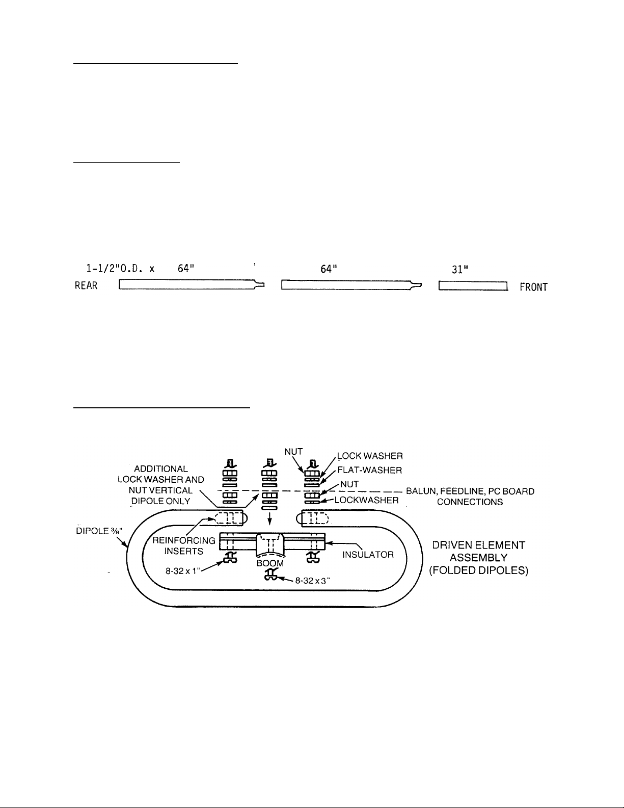
Each joint requires two sets of 8-32 x 1-3/4" screws, lock washers and nuts. Handtighten nuts securely. Section placement and length will follow the sketch below:
2. Mount 1" steel clip to right side of boom (when viewed from rear) using the hole
25-1/2" from rear. Secure with 6-32 x 1-3/4" hardware.
DRIVEN ELEMENT ASSEMBLY
3
 Loading...