

Page 1
Icon Series
Owner's Manual
Page 2
Important Safety Information
1. REA D these instructions.
2. KEEP these instructions.
3. HEED all warnings.
4. FOLLOW all instructions.
5. DO NOT use this apparatus near water.
6. CLE AN ONLY with dry cloth.
7. DO NOT block any ventilation openings. Install in
accordance with the manufacturer’s instructions.
8. DO NOT install near any heat sources such as radiators,
heat registers, stoves, or other apparatus (including
amplifier s) that produce heat.
9. ONLY USE attachments/accessories specified by the
manufacturer.
10. USE only with a cart, stand, tripod, bracket,
or table specified by the manufacturer, or sold
with the apparatus. When a cart is used,
use caution when moving the cart/apparatus
combination to avoid injury from tip-over.
11. DO NOT expose this apparatus to dripping or splashing and
ensure that no objects filled with liquids, such as vases,
are placed on the apparatus.
REFER all servicing to qualified service personnel.
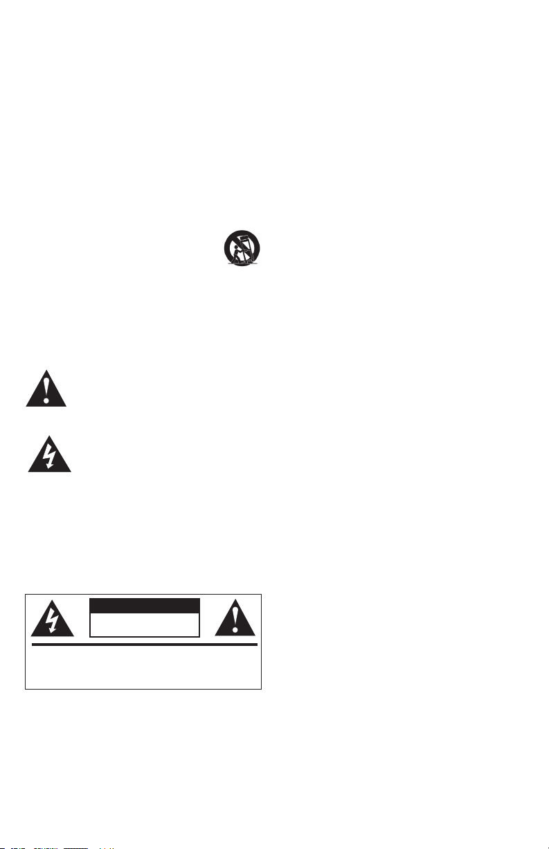
The exclamation point, within an equilateral triangle, is
intended to alert the user to the presence of important
operating and maintenance (servicing) instructions in
the literature accompanying the product.
The lightning flash with arrowhead symbol within an
equilateral triangle, is intended to alert the user to the
presence of uninsulated “dangerous voltage” within
the product’s enclosure that may be of sufficient
magnitude to constitute a risk of electrical shock to
persons.
WARNING:
To reduce the risk of fire or electrical shock, do not expose
this apparatus to rain or moisture.
WARNING: No naked flame sources – such as candles – should be
placed on the product.
WARNING
RISK OF ELECTRIC SHOCK.
DO NOT OPEN.
WARN ING: D o Not Open! Risk of Electrical Shock . Voltages in this
equipment are hazardous to life. No user-serviceable par ts inside.
Refer all ser vicing to qualified service personnel.
Icon Series Loudspeaker
Thank you for your purchase of this Icon Series Loudspeaker. In total,
there are five wood finish models within the Icon Series: the WF-35
and WF-34 floorstanding speakers, the WB-14 bookshelf speaker,
the WC-24 center channel speaker and the WS-24 surround channel
speaker.
All of these speakers utilize a new wide dispersion Tractrix® Hornloaded tweeter with XT
sound in a smooth, enveloping 80-degree by 80-degree pattern. As
with all Klipsch horn-loaded technology, this version also produces
more output using less energy and delivers the company’s signature
dynamic sound.
Please be sure to fill out the product registration card included with
this manual or online at www.klipsch.com so we are better able to
serve you.
TM
technology. This proprietary design radiates
Inspection
Please check promptly for any transit damage. Carefully unpack
your new speaker system and verify the components against the
packing list. In extreme circumstances, items may have become
damaged in transit. If any damage is discovered, notify the delivery
service and dealer where the system was purchased. Make a
request for inspection, and follow their instructions for evaluation.
Be sure to keep the product’s original shipping carton.
Bookshelf and Center
These models are supplied with self-stick rubber feet to prevent
surface damage. (See Figure 1 for proper application.)
Room Placement
Your Icon loudspeakers will perform well in a variety of locations,
but best results will be achieved using the following guidelines:
Front Left and Right Speakers ( See Figures 2A and 2B.)
• Place on a common wall 6 to 15 feet apart.
• If used in a home theater system, position the speakers
flanking your video display.
• Position them equal distance from the front wall (if they are
not wall-mounted).
• Position them at the same height above the oor
(for non-floor standing models) with the high frequency
drivers at seated ear height.
• Angle speakers toward the listener and even with or forward
of any adjacent obstructions (if they are not wall-mounted) .
• Placing them near a corner or wall provides the greatest
amount of bass while moving the speakers away from room
boundaries reduces bass energy.
• Asymmetrical placement of a pair of speakers from adjacent
side walls can smooth room-induced bass unevenness.
• Bookshelf models may be placed on shelves, optional oor stands
or on walls using appropriate brackets.
• Experiment with the ab ove guidelines to suit your taste and to
compensate for your room’s acoustic characteristics.
2
Page 3

Center Channel Speaker (See Figures 2A and 2B.)
• Place immediately above or below the center of your video display.
Surround Channel Speakers (See Figures 2A, 2B and 3.)
• Place above seated ear height on side or rear walls
(approximately 4-5 feet above the floor).
• Use the at tached wall brackets to hook to appropriately sized
screw heads screwed into a wall stud and wall anchor or two
wall anchors with a suitable weight bearing capacity. ( See
Figure 3. )
On Wall Placement
• Icon bookshelf models may be wall-mounted using the
1
/4-20 threaded insert on the rear of the speaker. Be sure
the mounting hardware you are using has the necessary load
bearing capabilities before hanging any speaker. If you use
a bracket, see the bracket owner’s manual for mounting details.
Never use the wall bracket for mounting the speaker to
the ceiling.
Bi-Wire Connections (See Figure 5.)
• The WF-35 and WF-34 are equipped with two pair of
connection terminals for bi-wire hookup and enhanced
performance.
• Remove the metal coupling straps.
• Connect one speaker wire ( + and -)to the top pair of binding
posts and a second speaker wire (+ and -) to the bottom pair
of binding posts.
Bass Management
When using your speakers in a home theater system, consult
the owner’s manual of your surround electronic s for proper
application of bass management settings.
• As a general rule, compact speakers (Bookshelf, Center
Channel and Surrounds ) are set to the “Small,” or bass limited set ting.
• Floorstanding speakers are typically set to the “Large,” or
full-range setting.
• Also refer to the electronics instructions for adjusting the
relative volume levels of the speakers so they are at the same
level when listened to from the primary listening position.
Connecting
Turn your amplifier off before making any
connections.
• Your loudspeakers are equipped with positive (Red) and negative
(B lack) connection terminals on the rear of the cabinet. These
correspond to the positive and negative terminals on the
appropriate channel ( left, right, center, rear etc.) of your amplifier.
Standard Connections (See Figure 4.) (All Models)
• All speakers in your system must be connected in phase with
the positive speaker terminal connected to the positive
amplifier terminal. Repeat this for the negative speaker
terminal and amplifier terminals. Most speaker wire has
distinguishing markings on the insulation of one of the
conductors to assist in correct hookup.
• Use 16 gauge (AWG), t wo conductor, copper wire at a
minimum and larger gauge wire for longer runs. The
connection terminals on your loudspeaker will accommodate
bare wire, spade terminals, and banana plugs.
With all connection types, take care that there is no
contact between the positive and negative terminals
at the speaker and amplifier. Damage to your equipment
may result.
WF-35 and WF-34 Standard Connections
• Use either pair of positive and negative terminals keeping the
metal coupling straps in place.
Care and Cleaning
• Occasional dusting or wiping of the cabinet with a cloth
is all that is required. Never use abrasive or solvent type
cleaners or harsh detergents.
• A vacuum cleaner with a soft brush attachment may be used
to clean the grille fabric.
• Never spray polishes or cleaners on the drive units (woofers,
midranges or tweeters ).
3
Page 4

Warranty – U.S. and Canada
Klipsch warrants to the original retail purchaser that this product is
to be free from defective materials and workmanship for a period
of five (5) year, from the date of purchase, if it is properly used and
maintained. If this product proves defective in either material or
workmanship, Klipsch, at its option, will (a) repair the product, or (b)
replace the product, at no charge for parts or labor. If the product
model is no longer available and cannot be repaired effectively or
replaced with an identical model, Klipsch at its sole option may
replace the unit with a current model of equal or greater value. In
some cases, modification to the mounting surface may be required
where a new model is substituted. Klipsch assumes no responsibility
or liability for such modification. To obtain a repair or replacement
under the terms of this warranty, please return to dealer first, if possible, and they will direct you accordingly for repairs or replacement.
You will be required to submit a copy of the original receipt.
Limitations:
• This limited warranty does not cover failure of the product
resulting from improper installation, misuse, abuse, accident,
neglect, mishandling, or wear from ordinary use or environmen tal deterioration.
• This limited warranty does not cover cosmetic damage,
including paint damage, or consequential damage to other
components or premises which may result for any reason
from the failure of the product.
• This limited warranty is null and void for products not used in
accordance with Klipsch’s instructions.
• This limited warranty is null and void for products with altered or
missing serial numbers and for products not purchased from an
authorized dealer.
• This limited warranty terminates if you sell or otherwise transfer
this product to another party.
THIS WARRANTY GIVES YOU SPECIFIC LEGAL RIGHTS, AND YOU
MAY ALSO HAVE OTHER RIGHTS WHICH VARY FROM STATE TO
STATE, JURISDICTION TO JURISDICTION OR COUNTRY TO COUNTRY.
KLIPSCH’S RESPONSIBILITY FOR MALFUNCTIONS AND DEFECTS
IN HARDWARE IS LIMITED TO REPLACEMENT OR REPAIR AS SET
FORTH IN THIS WARRANTY STATEMENT. FOR CANADIAN
CUSTOMERS, KLIPSCH DISCLAIMS ALL OTHER WARRANTIES AND
CONDITIONS, EXPRESS OR IMPLIED, STATUTORY OR OTHERWISE,
FOR THE PRODUCT. FOR U.S. CUSTOMERS, ALL EXPRESS AND
IMPLIED WARRANTIES FOR THE PRODUCT, INCLUDING BUT NOT
LIMITED TO ANY IMPLIED WARRANTIES OF MERCHANTABILITY AND
FITNESS FOR A PARTICULAR PURPOSE ARE LIMITED IN TIME TO
THE TERM OF THIS WARRANTY. SOME STATES, JURISDICTIONS OR
COUNTRIES DO NOT ALLOW THE EXCLUSION OF CERTAIN IMPLIED
WARRANTIES OR CONDITIONS, OR LIMITATIONS ON HOW LONG AN
IMPLIED WARRANTY OR CONDITIONS LASTS, SO THIS LIMITATION
MAY NOT APPLY TO YOU. KLIPSCH DOES NOT ACCEPT LIABILITY
FOR SPECIAL, INDIRECT, CONSEQUENTIAL OR INCIDENTAL
DAMAGES, INCLUDING WITHOUT LIMITATION, ANY LIABILITY FOR
THIRD PARTY CLAIMS AGAINST YOU FOR DAMAGES OR FOR
PRODUCTS NOT BEING AVAILABLE FOR USE. THE MAXIMUM
LIABILITY FOR WHICH KLIPSCH MAY BE RESPONSIBLE WILL BE NO
MORE THAN THE AMOUNT YOU PAID FOR THE PRODUCT THAT IS
THE SUBJECT OF THE CLAIM. SOME STATES, JURISDICTIONS OR
COUNTRIES DO NOT ALLOW THE EXCLUSION OR LIMITATION OF
SPECIAL, INDIRECT, INCIDENTAL OR CONSEQUENTIAL DAMAGES,
SO THE ABOVE LIMITATION OR EXCLUSION MAY NOT APPLY TO YOU.
Warranty Outside the U.S. and Canada
The Warranty on this product if it is sold to a consumer outside of the
United States and Canada shall comply with applicable law. To obtain
any applicable warranty service, please contact the dealer from
which you purchased this product, or the distributor that supplied
this product.
EU Compliance Information
Eligible to bear the CE mark, Conforms to European Union Low Voltage Directive 73/23/EEC and 2006/95/EC; Conforms to European
Union EMC Directives 89/336/EEC and 2004/108/EC.
WEEE Notice
Note: This mark applies only to countries within the European Union
(EU) and Norway.
This application is labeled in accordance with
European Directive 2002/96/EC concerning waste
electrical and electronic equipment (WEEE). This label
indicates that this product should not be disposed of
with household waste. It should be deposited at an
appropriate facility to enable recovery and recycling.
4
Page 5

Figure 1
Speaker Bottom
Figure 2A - Traditional Front Speaker Placement
5
Page 6

Figure 2B - On-Wall Front Speaker Placement
Figure 3
Correct placement
for wall bumpers
6
Page 7

Right Speaker
Left Speaker
AMP
All Power Off!
Figure 4
Right Speaker
Left Speaker
AMP
All Power Off!
AMP
All Power Off!
Left Speaker Right Speaker
Figure 5
7
Page 8

Power
Detail
Emotion
For over 60 years, we’ve made speakers for people who are as passionate about
great sound as we are. That’s why every Klipsch speaker is horn-loaded to create
a remarkably accurate listening experience for your music and movies. From our
smallest satellites to our acclaimed professional theater installations, our speakers
deliver sound that’s so lifelike, you have to feel it to believe it.
THE ULTIMATE SOUND EXPERIENCE
TM
 Loading...